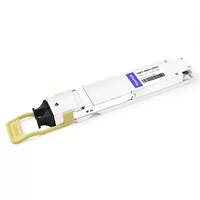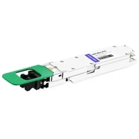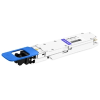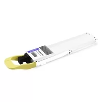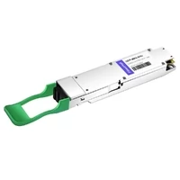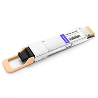

What happens when your AI data center switches have already moved to 400G or 800G, while a large number of servers, NICs, DPUs, and existing network devices still operate at 100G or 200G?
Replacing every device at the same time is rarely practical.
This is where port breakout becomes important.
Breakout allows one high-speed switch port to operate as multiple lower-speed logical ports. Common configurations include:
- 800G to 4×200G
- 800G to 8×100G
- 800G to 2×400G
- 400G to 2×200G
- 400G to 4×100G
For AI data centers, this provides a practical way to connect next-generation 400G and 800G switches to existing 100G and 200G infrastructure while increasing port utilization and allowing the network to migrate gradually.
As generative AI, large language model training, and high-performance computing continue to increase network bandwidth requirements, 100G, 200G, 400G, and 800G equipment will often coexist in the same infrastructure for years.
Breakout therefore is not simply a cabling technique. It is an important part of the migration strategy from existing data center networks to higher-speed AI fabrics.
In this guide, we cover:
- How port breakout works
- Why AI data centers need breakout
- Common 400G and 800G breakout configurations
- 800G to 4×200G deployment
- 800G to 8×100G deployment
- 800G to 2×400G deployment
- 400G to 2×200G deployment
- 400G to 4×100G deployment
- How to select optics and breakout cables
- Key SerDes, FEC, and compatibility considerations
- How breakout can support 200G-to-800G migration
Quick Reference: Common 400G and 800G Breakout Configurations
| Switch Port | Breakout Configuration | Speed per Link | Typical Application |
| 400G | 2×200G | 200G | Connect two 200G NICs or switches |
| 400G | 4×100G | 100G | Connect four 100G NICs or switches |
| 800G | 2×400G | 400G | Connect two 400G NICs or switches |
| 800G | 4×200G | 200G | AI servers, NICs, and DPUs |
| 800G in 400G mode | 2×200G | 200G | Connect legacy 200G endpoints |
| 800G | 8×100G | 100G | High-density 100G connectivity |
There is one important rule to remember:
Having enough aggregate bandwidth does not automatically mean a port supports a specific breakout mode.
For example:
800G = 4 × 200G
mathematically.
However, an 800G switch port does not automatically support 4×200G breakout.
The complete path must support the required mode:
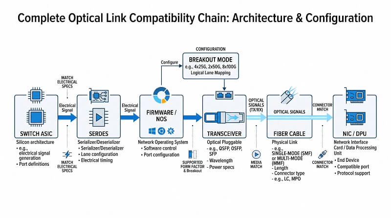
Switch ASIC → SerDes lanes → Port mode → Transceiver → Cable → NIC
The switch ASIC architecture, electrical lane configuration, operating system, transceiver design, cable topology, and destination interface must all be compatible.
What Is Port Breakout?
Port breakout is the process of dividing one high-speed physical switch port into several independent lower-speed logical interfaces.
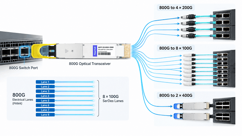
A typical 800G port can use:
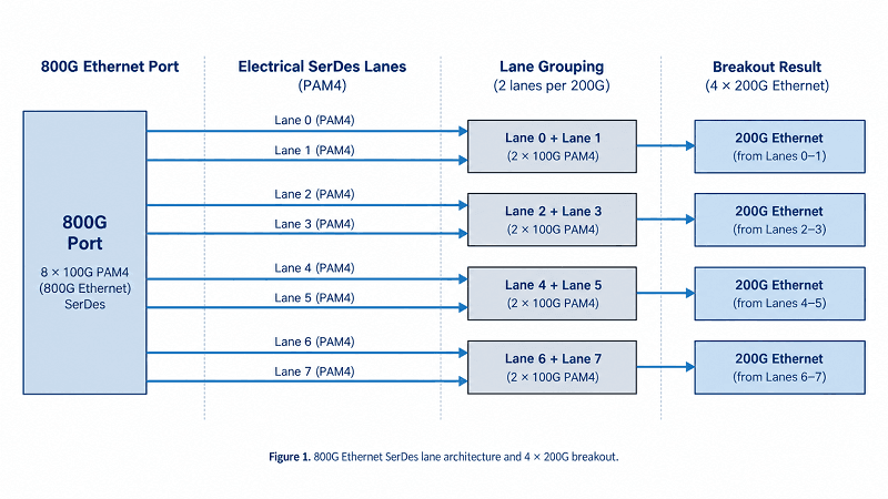
8 × 100G electrical SerDes lanes
When supported by the switch ASIC and port architecture, these lanes can be grouped into different logical configurations.
For example:
800G to 4×200G
The eight 100G electrical lanes are divided into four groups.
Each 200G logical link uses:
2 × 100G lanes
800G to 8×100G
Each 100G lane operates as an independent logical interface.
800G to 2×400G
The eight lanes are divided into two groups.
Each 400G logical link uses:
4 × 100G lanes
The switch first performs the logical port breakout.
The optical module, DAC, ACC, AOC, or breakout fiber then provides the physical connections between the high-speed port and the individual destination devices.
A complete breakout connection can therefore be represented as:
Switch ASIC
↓
SerDes / Breakout Port Configuration
↓
400G or 800G Transceiver
↓
Breakout Cable
↓
100G / 200G / 400G Transceiver
↓
NIC / DPU / Switch
This distinction is important because a breakout cable alone cannot convert one switch port into multiple logical interfaces.
The switch must first support the corresponding breakout mode.
Why Do AI Data Centers Need Port Breakout?
Connect 800G Switches to Existing 100G and 200G Devices
AI network components rarely upgrade at exactly the same time.
A new spine or leaf switch may already provide 800G ports, while the installed server infrastructure may still use:
- 100G QSFP28 NICs
- 200G QSFP56 NICs
- 200G QSFP112 NICs
- Existing 400G switches
Replacing every endpoint simultaneously can create unnecessary cost and operational disruption.
Breakout allows the new switch to continue supporting these devices.
For example:
800G Switch → 4×200G NICs
or:
800G Switch → 8×100G NICs
This provides a much smoother migration path.
Improve 800G Switch Port Utilization
An 800G port provides a large amount of bandwidth.
If the destination equipment only requires 200G, dedicating one entire 800G physical port to a single 200G endpoint would not make efficient use of the port capacity.
With:
1 × 800G → 4 × 200G
the same physical port can connect four independent 200G endpoints.
This is particularly useful in large GPU clusters where hundreds or thousands of NICs need to connect to the network fabric.
Support Gradual 200G-to-400G-to-800G Migration
Breakout allows network upgrades to happen in stages.
For example, a data center can first deploy an 800G spine while continuing to operate existing 200G leaf switches.
Phase 1
800G Spine
↓
800G to 4×200G Breakout
↓
200G Leaf / NIC
Phase 2
800G Spine
↓
800G to 2×400G Breakout
↓
400G Leaf
Phase 3
800G Spine
↓
Native 800G
↓
800G Leaf
This approach extends the usable life of existing NICs and switches while reducing the amount of equipment that must be replaced during each upgrade cycle.
Increase Connection Density in AI Clusters
AI clusters require very high network connection density.
A large GPU cluster can contain hundreds or thousands of network interfaces.
Breakout makes it possible to use high-bandwidth switch ports more efficiently without significantly increasing the number of physical switch ports.
Benefits can include:
- Higher switch port utilization
- Higher server connection density
- More flexible rack design
- Reduced switch count in some architectures
- Easier migration between network generations
Common 800G Breakout Solutions
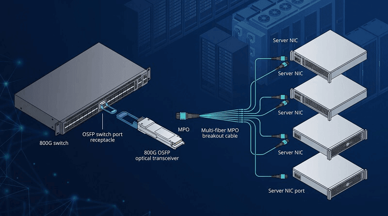
800G to 4×200G Breakout
800G to 4×200G is one of the most important breakout configurations for current AI data center deployments.
A typical topology is:
800G OSFP Switch
↓
4×200G Breakout
↓
4 × 200G NIC / DPU / Switch
This configuration can be used to connect an 800G OSFP switch to 200G QSFP56, QSFP112, or other supported 200G interfaces.
Multimode Optical Example
One implementation uses an:
on the switch side.
The module provides two optical interfaces.
Two 1:2 multimode MPO breakout cables can then connect the 800G side to four downstream 200G links.
Depending on the destination interface and switch support, downstream modules can include compatible OSFP or QSFP112 modules operating at the required 200G rate.
The resulting topology is:
800G OSFP Switch
↓
OSFP-800G-2×SR4
↓
2 × 1:2 Multimode MPO Breakout Cables
↓
4 × 200G Optical Links
↓
4 × 200G NICs / DPUs
For short-distance applications, other options may include:
- DAC
- ACC
- AOC
- Multimode optical modules
For longer distances, single-mode optical solutions can be used.
800G to 8×100G Breakout
800G to 8×100G is particularly useful when a new 800G switch must connect to a large number of existing 100G servers or access switches.
A typical topology is:
800G OSFP Switch
↓
8×100G Breakout
↓
8 × 100G NICs or Switches
One single-mode implementation uses:
OSFP-800G-2×DR4
on the switch side.
The eight 100G optical lanes can be distributed using two 1:4 MPO-to-LC breakout fiber assemblies.
Each breakout branch then connects to a 100G DR optical module.
The connection becomes:
800G OSFP Switch
↓
OSFP-800G-2×DR4
↓
2 × 1:4 MPO-to-LC Single-Mode Breakout Cables
↓
8 × QSFP-100G-DR
↓
8 × 100G NICs / Switches
This configuration is suitable for:
- 800G switch to 100G server migration
- High-density 100G server access
- Reuse of existing 100G NICs
- Aggregation of multiple 100G devices
800G to 2×400G Breakout
As more AI networks migrate from 400G toward 800G, 800G to 2×400G becomes another important transition architecture.
A typical topology is:
800G Switch
↓
2×400G Breakout
↓
2 × 400G NICs or Leaf Switches
This is particularly useful in:
- 800G spine to 400G leaf networks
- Mixed 400G and 800G AI fabrics
- Incremental 400G-to-800G migrations
- Environments where 400G NICs remain in service
Instead of replacing the entire 400G layer immediately, the spine can be upgraded first while the existing 400G endpoints remain connected through breakout.
As the leaf layer is later upgraded to 800G, the breakout connection can be replaced with native 800G links.
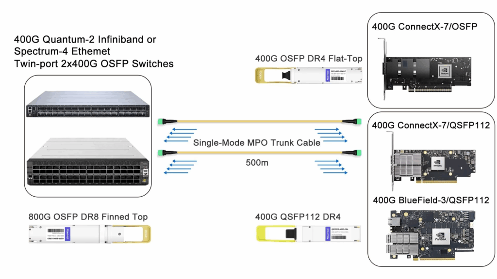
Using an 800G Switch Port at 400G for 2×200G
Some deployment scenarios require an 800G-capable switch port to operate at 400G and then break out into two 200G links.
A typical topology is:
800G-capable OSFP Switch Port
↓
Port Configured for 400G
↓
400G to 2×200G
↓
2 × 200G QSFP56 NICs
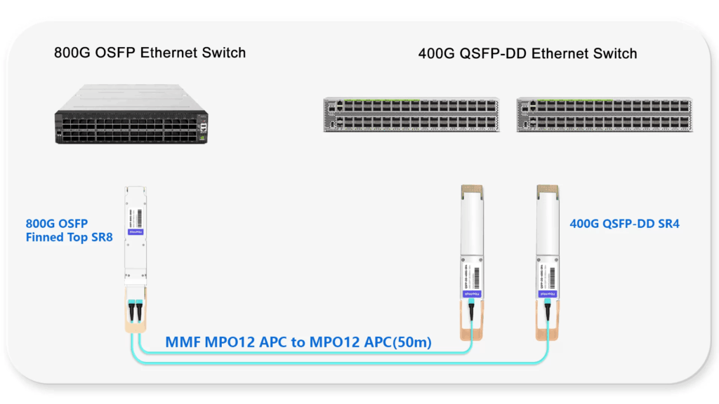
For a multimode implementation, the switch side can use a 400G 2×SR4-type optical module with two MPO interfaces.
Each optical path then connects to a 200G SR4 module.
This architecture is useful when an 800G-capable platform needs to support existing 200G infrastructure during a transition period.
Common 400G Breakout Solutions
400G breakout remains widely used because many AI and traditional data center environments still contain large numbers of 100G and 200G endpoints.
The two most common configurations are:
- 400G to 2×200G
- 400G to 4×100G
400G to 2×200G Breakout
A typical application is:
400G Switch
↓
2×200G Breakout
↓
2 × 200G NICs / Switches
Several implementations are possible depending on the switch port form factor and the destination interface.
QSFP112 Switch to 200G QSFP56 NIC
One multimode example uses:
Q112-400G-SR8
on the switch side.
The module includes a gearbox that converts:
4 × 100G electrical lanes
to:
8 × 50G optical lanes
A 1:2 multimode breakout cable can then divide the eight optical lanes into two groups of four.
Each group connects to a:
Q56-200G-SR4
module.
The topology becomes:
400G QSFP112 Switch
↓
Q112-400G-SR8
↓
1:2 Multimode MPO Breakout Cable
↓
2 × Q56-200G-SR4
↓
2 × 200G QSFP56 NICs
QSFP112 Switch to 200G QSFP112 NIC or DPU
When both sides use the QSFP112 ecosystem, another implementation can use:
Q112-400G-VR4/SR4
↓
1:2 Multimode Breakout Cable
↓
2 × Q112-200G-VR2/SR2
This configuration is suitable for 400G QSFP112 switches connecting to 200G QSFP112 NICs or DPUs.
The use of QSFP112 on both ends can simplify electrical lane matching in supported platforms.
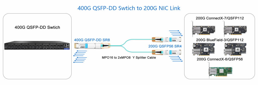
QSFP-DD Switch to 200G QSFP56 or QSFP112 NIC
For QSFP-DD switch platforms, a 400G parallel optical module can also provide 2×200G connectivity.
A typical multimode solution uses:
QDD-400G-SR8
↓
1:2 Multimode MPO Breakout Cable
↓
2 × 200G SR4 Modules
↓
2 × 200G NICs
The exact downstream module should be selected according to the NIC form factor, optical lane rate, switch configuration, and compatibility requirements.
400G to 4×100G Breakout
400G to 4×100G is one of the most established breakout architectures in modern data centers.
A typical topology is:
400G QSFP-DD Switch
↓
4×100G Breakout
↓
4 × 100G NICs / Switches
A common single-mode implementation uses:
QDD-400G-DR4
↓
1:4 MPO-to-LC Single-Mode Breakout Cable
↓
4 × QSFP-100G-DR
↓
4 × 100G NICs
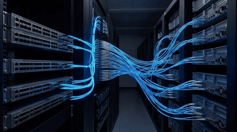
The 400G DR4 module carries four independent 100G optical lanes.
The breakout cable separates these lanes into four individual 100G optical paths.
This configuration is particularly useful for:
- 400G leaf to 100G server connections
- 400G aggregation to 100G access
- Migration from 100G to 400G
- Reuse of existing 100G NIC infrastructure
DAC vs ACC vs AOC vs Optical Breakout
Not every breakout connection requires discrete optical transceivers.
The correct interconnect depends heavily on distance, rack layout, power requirements, and cabling design.
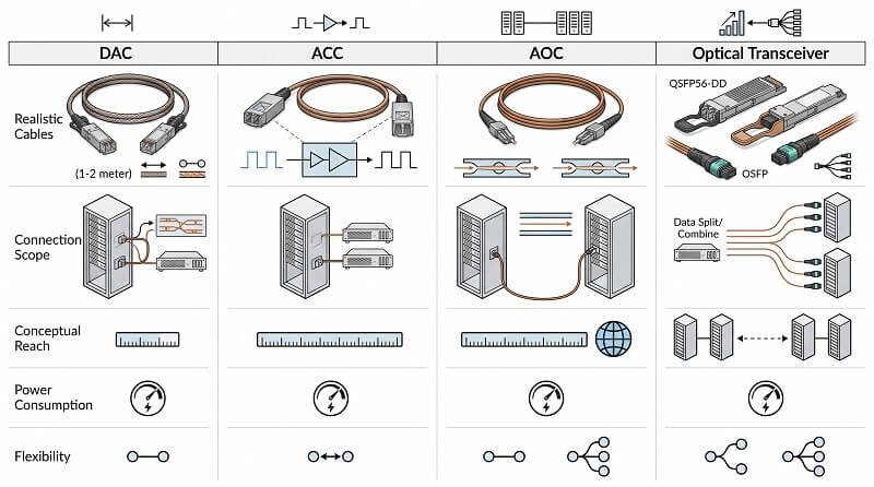
DAC
Direct Attach Copper is generally best for very short connections.
Typical use:
Switch ↔ NIC within the same rack
Advantages include:
- Low power consumption
- Low latency
- Lower cost
- No separate optical modules required
However, reach is limited and cable diameter can become an issue at higher data rates.
ACC
Active Copper Cable adds signal conditioning to improve high-speed electrical transmission over longer distances than passive DAC.
ACC can be useful when:
- The reach exceeds practical passive DAC limits
- Copper connectivity is preferred
- A full optical solution is unnecessary
AOC
Active Optical Cable integrates the optical engines into the cable assembly.
It provides:
- Longer reach than copper
- Lower cable weight
- Easier handling at higher speeds
- No need to separately match optical transceivers and fiber assemblies
AOCs are commonly used for rack-to-rack or high-density short-reach connectivity.
Optical Transceivers + Breakout Fiber
For longer distances or structured fiber infrastructure, discrete optical modules and breakout fiber assemblies provide greater flexibility.
They allow designers to select:
- Multimode or single-mode fiber
- MPO/MTP or LC interfaces
- Different transmission reaches
- Different optical standards
As a general deployment principle:
Very short reach: DAC
Short to medium reach: ACC or AOC
Structured multimode links: Multimode optics
Longer reach: Single-mode optics
How to Choose the Right Breakout Solution
Selecting a breakout solution should start with the complete link rather than with the cable.
Instead of asking:
“Which 800G to 4×200G cable should I buy?”
start by verifying the following parameters.
Confirm the Switch Port Speed
Check the native speed of the switch port:
- 200G
- 400G
- 800G
Then confirm the speed required at each destination.
For example:
800G → 4×200G
or:
400G → 4×100G
Confirm the Supported Breakout Mode
The switch must explicitly support the required logical configuration.
Possible examples include:
- 2×400G
- 4×200G
- 8×100G
- 2×200G
- 4×100G
Support depends on the switch ASIC, hardware layout, firmware, and network operating system.
Do not assume that a port supports a configuration simply because the aggregate bandwidth matches.
Verify the SerDes Lane Architecture
SerDes configuration is one of the most important factors in breakout compatibility.
Check:
- Number of electrical lanes
- Data rate per lane
- PAM4 signaling rate
- Lane grouping
- Gearbox requirements
For example, an 800G port based on eight 100G electrical lanes is naturally suited to certain breakout combinations.
However, the specific implementation must still be supported by the switch ASIC and transceiver architecture.
Check the Transceiver Lane Architecture
Two optical modules with the same aggregate data rate do not necessarily have the same internal architecture.
The module may use:
- Parallel optics
- Wavelength-division multiplexing
- Gearbox conversion
- DSP-based conversion
- Different optical lane counts
These differences directly affect breakout capability.
For example, a parallel optical module may make it possible to separate individual optical lanes, while a wavelength-multiplexed module may require a different breakout architecture.
Verify FEC Compatibility
High-speed PAM4 transmission relies heavily on Forward Error Correction.
A breakout connection must maintain compatible FEC behavior across:
Switch → Transceiver → Link → Transceiver → NIC
A physical connection can be correct while the Ethernet link still fails because the two endpoints are using incompatible FEC settings or modes.
This becomes increasingly important at 200G, 400G, and 800G.
Select the Correct Fiber and Connector
The cabling architecture must match the optical module.
Check:
- Multimode vs single-mode
- MPO/MTP vs LC
- Fiber count
- Breakout polarity
- APC vs UPC
- Connector keying
- Transmission distance
Incorrect polarity or connector selection can prevent an otherwise compatible breakout design from working.
Verify the Destination Port
The receiving device can be:
- QSFP28
- QSFP56
- QSFP112
- QSFP-DD
- OSFP
Form factor alone does not guarantee compatibility.
The port must support the target speed, lane rate, FEC mode, and optical standard.
Verify End-to-End Compatibility
The most important rule is to validate the complete chain:
Switch
↓
NOS / Firmware
↓
Port Breakout Mode
↓
SerDes
↓
Transceiver
↓
Cable / Fiber
↓
Destination Transceiver
↓
NIC / DPU / Switch
A breakout design should not be approved based only on the specification of one component.
AIDC Breakout Migration Strategies
Breakout is especially valuable when data center network generations overlap.
Rather than upgrading every layer at once, operators can use different migration strategies.
Strategy 1: Spine-First Upgrade
This approach is suitable when the existing leaf switches are still usable but the spine requires additional capacity.
Step 1
Upgrade the spine to 800G.
Step 2
Use:
800G → 2×400G
or:
800G → 4×200G
to continue connecting existing leaf switches.
Step 3
Upgrade the leaf switches gradually.
Step 4
Replace breakout connections with native 800G links when both sides support 800G.
Best for:
Existing 200G or 400G networks with healthy leaf infrastructure.
Strategy 2: Upgrade High-Bandwidth AI Racks First
Some AI racks generate much more traffic than the rest of the data center.
Instead of upgrading the entire fabric, operators can first move these racks to higher-speed leaf switches.
For example:
800G Leaf
↓
Breakout or native 400G
↓
Existing Spine
As traffic grows, the spine can then be upgraded.
Best for:
GPU training clusters and other high-bandwidth compute zones.
Strategy 3: Skip 400G and Move Directly from 200G to 800G
A data center currently operating at 200G may consider skipping a full 400G switching generation.
Instead of:
200G → 400G → 800G
the network can move directly to:
200G → 800G
while using:
800G → 4×200G breakout
to maintain compatibility with existing 200G equipment.
As the endpoints are refreshed, individual breakout connections can be replaced with 400G or native 800G links.
This strategy can reduce the number of major switch replacement cycles.
Common Breakout Deployment Mistakes
Mistake 1: Assuming Bandwidth Math Equals Compatibility
800G divided by four equals 200G.
But that does not guarantee the switch supports 4×200G.
Always verify the actual breakout mode.
Mistake 2: Selecting the Cable Before the Optics
The cable cannot be selected correctly until the optical architecture is known.
First determine:
- Switch port
- Breakout mode
- Transceiver type
- Destination interface
Then select the corresponding fiber or cable.
Mistake 3: Ignoring Electrical Lane Rates
A 200G interface can be implemented using different electrical and optical lane structures.
Two modules with the same 200G aggregate rate are therefore not automatically interchangeable.
Mistake 4: Ignoring FEC
A link may have the correct optics and fiber but still remain down because of FEC mismatch.
Always check FEC settings on both endpoints.
Mistake 5: Treating Form Factor as the Only Compatibility Requirement
QSFP56, QSFP112, QSFP-DD, and OSFP describe physical and electrical module ecosystems, but not complete link compatibility.
Speed, lane structure, breakout mode, optics, and FEC must also match.
FAQ
Can an 800G Port Be Split into 4×200G?
Yes, if the switch ASIC, SerDes architecture, firmware, port configuration, transceiver, and cable all support 4×200G breakout.
The fact that:
800G = 4 × 200G
does not by itself guarantee compatibility.
Can an 800G Port Break Out to 8×100G?
Yes, on supported platforms.
One possible single-mode implementation uses:
OSFP-800G-2×DR4
with:
2 × 1:4 MPO-to-LC breakout cables
to connect:
8 × 100G DR modules
The switch must also be configured for 8×100G operation.
Can an 800G Port Connect to Two 400G Devices?
Yes, when the switch and optics support:
800G → 2×400G
This is a useful migration architecture for 800G spine switches connecting to existing 400G leaf switches or NICs.
Can a 400G Port Connect to Two 200G NICs?
Yes.
The switch must support:
400G → 2×200G
and the transceiver, electrical lanes, FEC, and breakout cable must match the two destination interfaces.
QSFP112 and QSFP-DD platforms can support different implementations depending on the hardware.
Can a 400G Port Connect to Four 100G Devices?
Yes.
A typical single-mode solution is:
400G QSFP-DD DR4
↓
1:4 MPO-to-LC Breakout
↓
4 × 100G DR
This is widely used for connecting 400G switches to existing 100G NICs or switches.
Is a Breakout Cable Enough to Split a Switch Port?
No.
The breakout cable only provides the physical connections.
The switch must also support the appropriate logical breakout mode.
The complete solution depends on:
ASIC + SerDes + Firmware + Port Configuration + Optics + Cable + Destination Device
What Is the Difference Between Port Breakout and Port Speed Downshift?
A port breakout creates multiple independent logical ports.
For example:
800G → 4×200G
A speed downshift keeps one physical/logical port but operates it at a lower total rate.
For example:
800G-capable port → 400G
In some applications, the two techniques can be combined.
For example, an 800G-capable port may first operate in 400G mode and then be configured as:
400G → 2×200G
Should I Use DAC, AOC, or Optical Modules for Breakout?
It depends primarily on transmission distance and cabling requirements.
Use DAC for very short connections.
Use ACC when additional copper reach is required.
Use AOC for short-to-medium high-speed links where lightweight optical cabling is preferred.
Use optical transceivers and breakout fiber for structured cabling and longer-distance links.
Conclusion
As AI data center networks evolve from 100G and 200G toward 400G, 800G, and eventually higher speeds, multiple generations of network equipment will continue to coexist.
Port breakout provides an effective way to bridge these generations.
Common deployment options include:
800G → 2×400G
800G → 4×200G
800G → 8×100G
400G → 2×200G
400G → 4×100G
The key is not simply finding a cable that physically divides one connector into several connectors.
A successful breakout deployment depends on the compatibility of the entire system:
Switch ASIC → SerDes → Firmware → Breakout Mode → Transceiver → Cable → NIC
By verifying each layer before deployment, network architects can reuse existing infrastructure, improve switch port utilization, and migrate AI fabrics to higher speeds without replacing every network component at once.
FiberMall provides high-speed optical interconnect solutions covering 200G, 400G, 800G, and next-generation data center networks, including optical transceivers, DACs, ACCs, AOCs, and breakout fiber assemblies.
Whether the goal is to connect a new 800G switch to existing 200G NICs, migrate a 400G fabric toward 800G, or build a new high-density AI cluster, the breakout architecture should be designed as a complete end-to-end link rather than as an individual cable or transceiver selection.
Planning an 800G or 400G breakout deployment? FiberMall can help verify switch, transceiver, cable, and NIC compatibility before deployment.
Related Products:
-
 NVIDIA MMA4Z00-NS Compatible 800GBASE 2 x SR4/SR8 OSFP PAM4 850nm 100m DOM Dual MPO-12 MMF Optical Transceiver Module
$550.00
-
NVIDIA MMA4Z00-NS-FLT Compatible 800GBASE 2 x SR4/SR8 OSFP RHS/Flat Top PAM4 850nm 100m DOM Dual MPO-12 MMF Optical Transceiver Module
$600.00
-
NVIDIA MMS4X00-NM Compatible 800GBASE 2 x DR4/DR8 OSFP IHS/Closed Finned Top PAM4 1310nm 500m DOM Dual MTP/MPO-12 SMF Optical Transceiver Module
$600.00
-
NVIDIA MMS4X00-NM-FLT Compatible 800GBASE 2 x DR4/DR8 OSFP Flat Top PAM4 1310nm 500m DOM Dual MTP/MPO-12 SMF Optical Transceiver Module
$650.00
-
NVIDIA MMS4X50-NM Compatible 800G 2x FR4 OSFP IHS/Closed Finned Top PAM4 1310nm 2km DOM Dual Duplex LC SMF InfiniBand NDR Optical Transceiver Module
$1000.00
-
NIVDIA MMS4X90-NR Compatible 800G OSFP 2xLR4 PAM4 CWDM4 Dual Duplex LC 10km SMF Optical Transceiver Module
$1200.00
-
NVIDIA MMS4A20-XM800 Compatible 800G DR4 OSFP224 4x200G-PAM4 1311nm 500m RHS/Flat Top DOM MTP/MPO-12 APC InfiniBand XDR Transceiver Module
$1300.00
-
OSFP-800G-2FR4 OSFP 2x400G FR4 PAM4 CWDM4 2km DOM Dual CS SMF Optical Transceiver Module
$1500.00
-
QSFP-DD-400G-SR8 400G QSFP-DD SR8 PAM4 850nm 100m MTP/MPO OM3 FEC Optical Transceiver Module
$149.00
-
QSFP-DD-200G-SR8 2x 100G QSFP-DD SR8 850nm 70m/100m OM3/OM4 MPO-16(APC) MMF Optical Transceiver Module
$350.00
-
OSFP-400G-SR8 400G SR8 OSFP PAM4 850nm MTP/MPO-16 100m OM3 MMF FEC Optical Transceiver Module
$299.00
-
Arista OSFP-800G-2FR4 Compatible 800G 2x FR4 OSFP IHS/Closed Finned Top PAM4 1310nm 2km DOM Dual Duplex LC SMF InfiniBand NDR Optical Transceiver Module
$1000.00