In the rapidly evolving world of AI servers and high-performance computing, effective thermal management is critical. Liquid cooling cold plates have emerged as a superior solution for dissipating heat from high-power processors in data centers and cloud environments. This in-depth guide covers everything from cold plate manufacturing and assembly to development requirements and rigorous testing methods, helping engineers and data center operators optimize AI server liquid cooling systems for reliability and performance.
Whether you’re designing next-generation AI infrastructure or seeking cost-effective cooling solutions, understanding cold plate technology is essential for achieving energy efficiency and sustained high performance.
I. Cold Plate Manufacturing and Assembly
1. Cold Plate Introduction
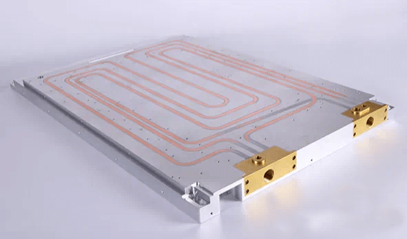
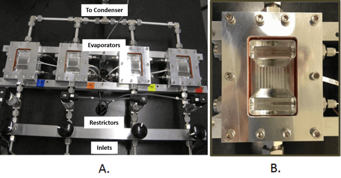
A cold plate is a heat sink integrated with pipelines or flow channels, allowing coolant to flow through and efficiently dissipate heat.
A cold plate assembly typically consists of a fluid heat exchanger and a mounting bracket. The fluid heat exchanger is connected to fluid pipelines via metal joining processes such as welding, brazing, or soldering.
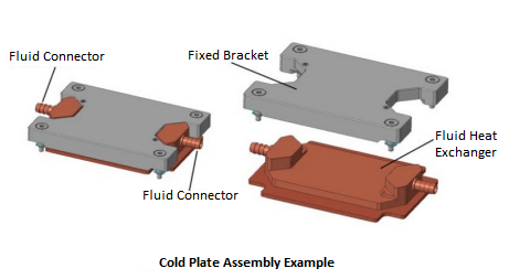
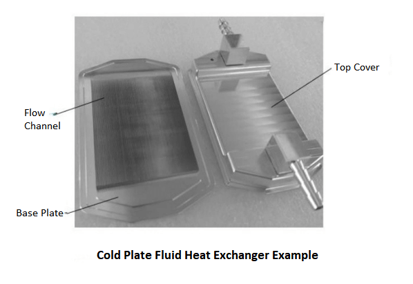
The cold plate heat exchanger comprises a base and a top cover.
The base is designed for direct contact with the processor. A compatible TIM2 (Thermal Interface Material) must be applied between the processor and the base to enhance the thermal performance of the cold plate solution. The top cover seals the fluid channels and usually integrates fluid connectors to direct coolant flow through the channels.
2. Types of Cold Plates
Cold plates are primarily divided into integral cold plates and split-type cold plates:
- Integral Cold Plate: The fluid heat exchanger and mounting bracket are integrated as one piece and cannot be separated. Due to the bracket being tied to the cold plate design, it is difficult to adapt to subsequent generations of processors.
- Split-Type Cold Plate: The fluid heat exchanger and mounting bracket are independent components. This modular design allows adaptation to new-generation processors by redesigning only the bracket, while reusing the heat exchanger for cost savings.
3. Cold Plate Manufacturing
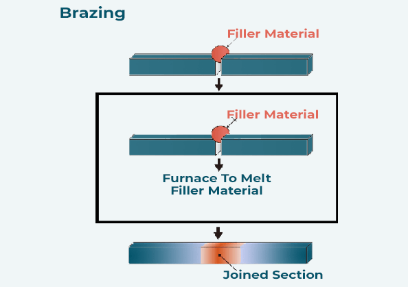
The primary assembly processes for the top cover and base of the cold plate heat exchanger include brazing, friction stir welding, soldering, and O-ring sealing. The table below (referenced in the original document) outlines the advantages and disadvantages of each process.
Deviations in manufacturing processes and insufficient process control can lead to product defects, affecting performance and reliability.
Cold plate product validation plans should include representative samples from the production line to evaluate performance and reliability within process control limits.
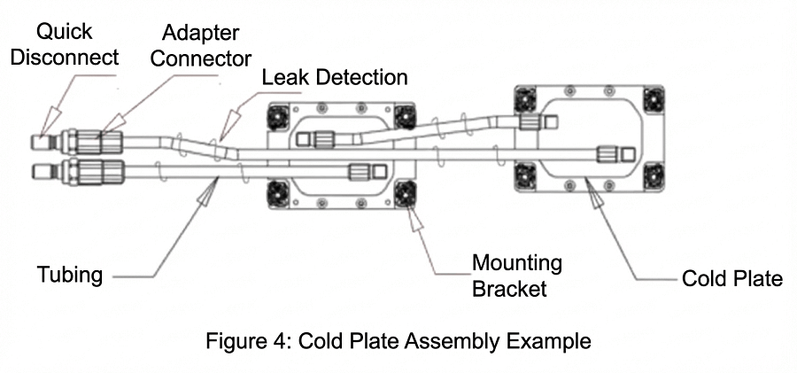
4. Cold Plate Assembly
The cold plate assembly consists of the cold plate, coolant tubes, and quick disconnects. Optional components in customer designs may include adapter connectors and leak detection hardware. Component descriptions:
- Coolant Tubes: Used to deliver coolant from the cooling loop to the cold plate. Metal materials can be copper or aluminum; non-metal options include PTFE (Polytetrafluoroethylene), PEX (Cross-linked Polyethylene), or EPDM (Ethylene Propylene Diene Monomer). Material selection must match the cold plate fluid connector type and design. Leak detection ropes/cables can be wrapped around pipes and connectors for monitoring.
- Quick Disconnects: Facilitate quick disconnection of the cold plate and tubes from the liquid cooling loop and IT equipment, improving maintainability.
- Adapter Connectors (Optional): Used to connect coolant tubes and quick disconnects in the assembly.
- Leak Detection (Strongly Recommended): Alerts data center operators upon detecting leaks.
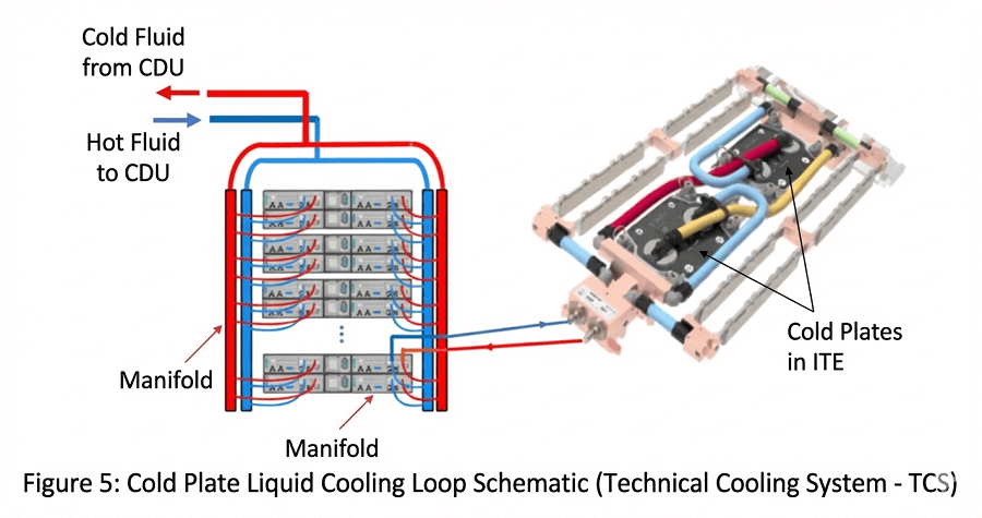
5. Cold Plate Technology Cooling System
The cold plate cooling system comprises IT equipment (ITE), cold plates, coolant tubes, quick disconnects (QDs), blade manifolds, secondary cooling loops, Coolant Distribution Units (CDU), facility water systems (FWS), and cooling towers or chillers.
This system provides temperature- and pressure-stable coolant to the cold plates. All wetted materials in contact with the coolant must be compatible.
II. Cold Plate Development Requirements
1. Mechanical Requirements
1) Cold Plate Mechanical Design
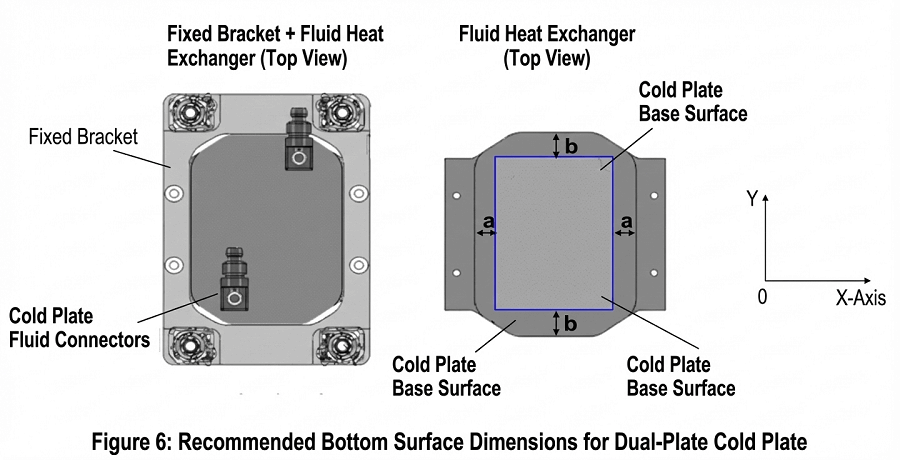
Cold plates must meet all structural requirements specified by the processor supplier for heat dissipation solutions (refer to key metrics in processor thermal and mechanical design guidelines, such as mass, flatness, etc.). Additional requirements include:
- Compliance with product design, Keep-Out Zone (KOZ), and Interface Control Document (ICD) for mounting hardware.
- Mechanical load applied by mounting hardware to the processor must meet package load requirements over the cold plate’s lifetime.
- Installation and removal procedures must comply with processor design and manufacturing guidelines.
- Base bottom surface flatness may affect mechanical and thermal performance; specifications must be defined per performance requirements.
- Average roughness (Ra) of the base bottom surface must be specified for mechanical and thermal performance.
- X and Y dimensions of the contact area with the processor IHS or die region affect thermal performance (blue outline in referenced Figure 6 represents processor IHS or die area).
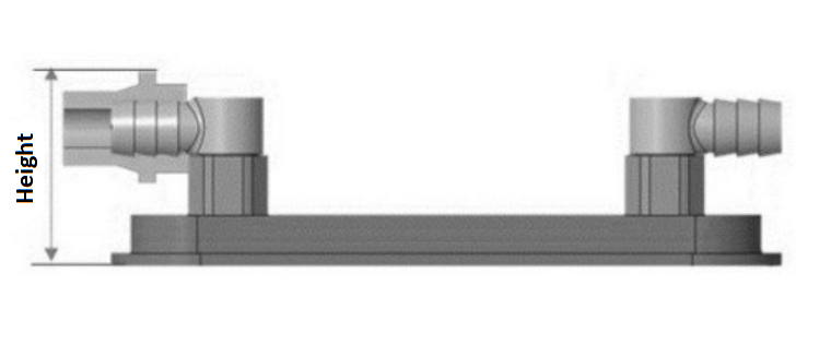
- Cold plate height must fit the product chassis, measured from base bottom to top of fluid connectors.
2) Cold Plate Fluid Connectors
Requirements:
- No leakage or deformation at connector-heat exchanger and connector-tube interfaces during hydrostatic testing.
- Design must prevent fluid stagnation or cavitation.
3) Cold Plate Cooling Loop Integration
Considerations:
- Connector position and orientation must accommodate product coolant tube routing.
- Electrode potential differences in wetted metals should be minimized to prevent corrosion; if dissimilar metals are used, integrated corrosion validation is strongly recommended.
- Electrochemical potential difference at any metal-metal interface must not exceed 0.15V to prevent galvanic corrosion.
- Fin thickness, height, and spacing in microchannel cold plates affect flow capacity and pressure drop.
- Assembly pressure drop must be below pump-provided fluid pressure.
- Understand coolant flow rate variations with temperature (as in referenced Figure 8) to adjust for seasonal changes.
4) Cold Plate Appearance Requirements
- Smooth top cover surface, no visible defects or deformation.
- Base bottom surface free of visible defects or deformation.
- Mounting bracket free of visible defects or deformation.
- Fluid connectors free of visible defects or deformation.
2. Thermal Performance Requirements
Cold plate performance must meet processor temperature requirements throughout its lifetime. Key thermal boundary conditions:
- Maximum allowable temperature from processor specs.
- Coolant temperature and flow rate provided by the system.
- Maximum inlet flow velocity < 1.5 m/s to prevent erosion.
3. Reliability Requirements
1) Hydrostatic Pressure
Comply with IEC FDIS 62368-1 standard; no detectable leakage or deformation post-test; dimensions statistically equivalent before and after.
2) Corrosion
- Fluid compatibility: Wetted surfaces chemically compatible and corrosion-resistant; maintain biocide and inhibitor concentrations.
- Salt spray test per ASTM B117: No corrosion, pitting, or discoloration; recommend post-test hydrostatic testing.
3) Dynamics Performance
- Shock: Post-test hydrostatic and thermal performance statistically equivalent.
- Vibration: Similar requirements.
4) Temperature Cycling
Recommended; post-test hydrostatic for leakage detection.
III. Cold Plate Testing Methods
1. Mechanical Testing
- Dimensional Testing Verify that the cold plate dimensions meet product requirements using the following methods:
- Measure the cold plate height using a vernier caliper.
- Measure the length, width, pitch, and height of the internal fluid flow channels using a vernier caliper.
- Use X-ray or similar imaging techniques to confirm that the fluid flow channel fins are free from distortion, deformation, or contaminants.
- Structural Testing Refer to the processor technical specifications to verify key structural requirements of the cold plate heat dissipation solution (such as mass, flatness, etc.), and adopt the testing methods recommended in the specifications.
- Cold Plate Integration Testing The cold plate must undergo the following verifications to ensure the design meets assembly requirements:
- Use X-ray or similar analysis methods to detect manufacturing defects in the cold plate heat exchanger (such as voids, channel contaminants, welding quality, etc.).
- For two-piece cold plates, verify that there is no interference between the heat exchanger and the mounting bracket during assembly.
- Check whether the connector specifications (such as dimensions, barb structure, installation orientation, etc.) meet the product design requirements.
- Integrate the cold plate into the product cold plate assembly and perform a hydrostatic pressure test to confirm no leaks between the heat exchanger, connectors, and coolant tubes.
- Appearance Testing
- Perform visual inspection of the cold plate external surface according to factory appearance inspection standards.
- Immerse the cold plate heat exchanger in an ultrasonic cleaning device (or equivalent equipment), flush with clear fluid, and verify that the discharged fluid shows no discoloration and that suspended particles in the rinse liquid are smaller than 50 μm.
2. Performance Testing
1) Thermal Performance Testing
Apply TIM2, install on functional processor, stabilize, record parameters. Thermal resistance calculated as:
R = (Tc – TL) / Q
(where R in °C/W, Tc case temperature, TL inlet temperature, Q power).
Test at multiple flow rates (referenced Figure 9 example).
2) Fluid Pressure Drop Testing
Setup lab TCS loop (referenced Figure 10a/b); measure differential pressure.
Pressure drop must allow positive flow.
3. Reliability Testing
1) Hydrostatic Pressure Test
The hydrostatic pressure test is a key quality and reliability test for detecting leaks under normal and expected operating conditions. It can refer to the following two industry standards:
European Standard EN 1779 [7] (Leak detection methods using pressurized gas):
- Pressure decay test: Measure the drop in total pressure of the cold plate; it is recommended that the pressure drop does not exceed 0.5%.
- Immersion bubble test: Pressurize the cold plate and immerse it in a fluid, detecting leaks by observing bubbles or bubble streams.
UL Solutions Standard IEC FDIS 62368-1 [8] (Specifies pressurization time and safety factors for hydrostatic leak testing):
- Pressurize the cold plate to the maximum working pressure, hold for 5 minutes, and check for leaks in the cold plate and connectors.
- Pressurize the cold plate to 3 times the maximum working pressure, hold for 2 minutes, and check for leaks in the cold plate and connectors.
The test medium can be gas or coolant.
2) Corrosion Testing
Fluid Compatibility Testing: Cold plate liquid cooling systems are composed of metal and polymer/elastomer materials, all of which are in contact with the coolant. The reliability of the cold plate depends on the chemical compatibility between the coolant and all wetted materials—the coolant must provide reliable corrosion protection for metal components and must not cause polymer/elastomer materials to leach contaminants (some polymer/elastomer materials may absorb corrosion inhibitors from the coolant, reducing their effectiveness).
Recommended methods for evaluating fluid compatibility include:
- Conduct corrosion and material compatibility testing of coolant with metals according to ASTM D2570 standard, evaluating the effects of circulating coolant on metal specimens and detecting galvanic corrosion under controlled laboratory conditions.
- Measure metal ion concentrations in the solution using Inductively Coupled Plasma (ICP) method according to ASTM D6130 and D5185 standards to identify early signs of corrosion and develop preventive maintenance plans.
- Test the pH value and reserve alkalinity of the coolant according to ASTM D1287 and D1121 standards to assess coolant degradation due to the conversion of ethylene glycol to glycolic acid.
- Test chloride ions and other anion concentrations in the coolant using ion chromatography according to ASTM D5827 standard to evaluate the content of active anions that cause metal pitting.
- Use gas chromatography (GC) and liquid chromatography (LC) to test the coolant, track organic corrosion inhibitor concentrations, and identify other precipitated organic contaminants [9].
Salt Spray Testing: Conduct testing in a salt spray chamber according to ASTM B117 standard to evaluate the corrosion resistance of the external surface coating of the cold plate (passivation or anodization of the cold plate surface can reduce the risk of salt spray corrosion).
Test conditions are as follows:
- Seal the inlet and outlet of the cold plate and place the sample in a 35°C salt spray chamber.
- NaCl solution mass concentration: 5%.
- NaCl solution pH value: 6.5–7.2.
- Salt spray deposition rate: approximately 2 ml/hour/80 cm².
- Exposure test duration: 8 hours.
After salt spray testing, measure the thermal performance of the cold plate to ensure no statistically significant thermal degradation. It is recommended to simultaneously perform a hydrostatic pressure test to detect potential leaks caused by material degradation due to corrosion.
3) Dynamics Testing
Shock Testing: Mount the cold plate on the corresponding CPU stack of a representative product board and perform shock testing according to product validation requirements. After testing, visually inspect whether the cold plate appearance meets requirements and whether the CPU stack and product board are damaged. Perform a hydrostatic pressure test on the cold plate in its installed state to verify that shock stress has not caused leaks in the cold plate or connectors.
Vibration Testing: Mount the cold plate on the corresponding CPU stack of a representative product board and perform vibration testing according to product validation requirements. After testing, visually inspect whether the cold plate appearance meets requirements and whether the CPU stack and product board are damaged. Perform a hydrostatic pressure test on the cold plate in its installed state to verify that vibration stress has not caused leaks in the cold plate or connectors.
4) Temperature Cycling Testing
Apply the recommended TIM2 material to the cold plate and mount it on a functional processor stack of a representative product board. Perform temperature or power cycling testing according to product validation requirements—the temperature range must cover the extreme operating temperatures of the cold plate, and the number of cycles must match the estimated power cycles over the processor’s service life. After testing, the thermal performance of the cold plate must meet product validation requirements. Perform a hydrostatic pressure test on the cold plate in its installed state to verify that temperature cycling stress has not caused leaks in the cold plate or connectors.
Related Products:
-
 OSFP-800G85F-MPO60M 800G OSFP SR8 MPO-12 Female Plug Pigtail 60m Immersion Liquid Cooling Optical Transceivers
$2400.00
OSFP-800G85F-MPO60M 800G OSFP SR8 MPO-12 Female Plug Pigtail 60m Immersion Liquid Cooling Optical Transceivers
$2400.00
-
OSFP-800G85M-MPO60M 800G OSFP SR8 MPO-12 Male Plug Pigtail 60m Immersion Liquid Cooling Optical Transceivers
$2400.00
-
OSFP-800G85F-MPO5M 800G OSFP SR8 MPO-12 Female Plug Pigtail 5m Immersion Liquid Cooling Optical Transceivers
$2330.00
-
OSFP-800G85M-MPO5M 800G OSFP SR8 MPO-12 Male Plug Pigtail 5m Immersion Liquid Cooling Optical Transceivers
$2330.00
-
OSFP-800G85F-MPO1M 800G OSFP SR8 MPO-12 Female Plug Pigtail 1m Immersion Liquid Cooling Optical Transceivers
$2250.00
-
OSFP-800G85M-MPO1M 800G OSFP SR8 MPO-12 Male Plug Pigtail 1m Immersion Liquid Cooling Optical Transceivers
$2250.00
-
OSFP-400GF-MPO1M 400G OSFP SR4 MPO-12 Female Plug Pigtail 1m Immersion Liquid Cooling Optical Transceivers
$1950.00
-
OSFP-400GM-MPO1M 400G OSFP SR4 MPO-12 Male Plug Pigtail 1m Immersion Liquid Cooling Optical Transceivers
$1950.00
-
OSFP-400GF-MPO3M 400G OSFP SR4 MPO-12 Female Plug Pigtail 3m Immersion Liquid Cooling Optical Transceivers
$1970.00
-
OSFP-400GM-MPO3M 400G OSFP SR4 MPO-12 Male Plug Pigtail 3m Immersion Liquid Cooling Optical Transceivers
$1970.00
-
OSFP-400GF-MPO60M 400G OSFP SR4 MPO-12 Female Plug Pigtail 60m Immersion Liquid Cooling Optical Transceivers
$2025.00
-
OSFP-400GM-MPO60M 400G OSFP SR4 MPO-12 Male Plug Pigtail 60m Immersion Liquid Cooling Optical Transceivers
$2025.00