
Updated October 2026. This guide now covers DWDM equipment, the ITU-T G.694.1 channel grid, ROADM and OADM architectures, and 400G/800G coherent transport for long-haul and data center interconnect networks.
DWDM equipment multiplies the capacity of a single fiber pair by carrying dozens of independent optical signals simultaneously. Each signal uses a different wavelength of light, allowing a network to transport multiple terabits per second over existing fiber infrastructure. Dense wavelength division multiplexing (DWDM) is a fundamental technology behind telecommunications backbones, metro networks, and high-speed connections between AI and cloud data centers.
This guide explains what DWDM equipment is, how its components work together, and how to select the right hardware for different deployments. You will learn how DWDM differs from CWDM, how the ITU-T G.694.1 channel grid organizes wavelengths, and how to plan an optical link budget. You will also explore how coherent 400G and 800G technologies are transforming modern optical transport. Along the way, we will examine the essential DWDM components, from multiplexers and transceivers to optical amplifiers and ROADMs.
What Is DWDM?
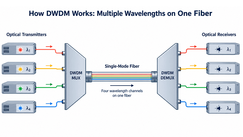
Dense wavelength division multiplexing is an optical transmission technique that carries multiple data channels over a single fiber by assigning each channel a different wavelength of light. A multiplexer combines these wavelengths onto the transmission fiber, while a demultiplexer separates them at the receiving end. By maintaining sufficient spectral separation between channels, DWDM allows multiple independent signals to share the same optical infrastructure.
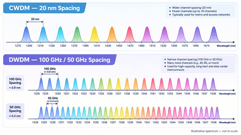
The word “dense” refers to the narrow spacing between optical channels. Traditional DWDM systems commonly use 50 GHz or 100 GHz channel spacing, enabling 40, 80, 96, or more channels, depending on the available optical spectrum and equipment design. Modern flexible-grid DWDM systems can allocate different spectral widths to accommodate high-baud-rate coherent signals.
Coarse wavelength division multiplexing (CWDM), by comparison, uses much wider channel spacing and typically supports fewer wavelengths.
Two properties make DWDM attractive to network operators. First, its optical multiplexing layer can transport different client protocols, including Ethernet, Fibre Channel, and Optical Transport Network (OTN) traffic, provided suitable transponders or interfaces are used. Second, DWDM is scalable: operators can increase capacity by activating additional wavelengths rather than deploying new fiber cables.
Dense wavelength division multiplexing transforms existing fiber infrastructure into a scalable, high-capacity optical transport platform.
How DWDM Equipment Works: Wavelengths as Channels
A DWDM system treats each wavelength as a separate logical link. The optics on each end agree on a channel plan, and every channel occupies a defined slice of the optical spectrum. Because the channels do not overlap, they can carry independent, unrelated signals.
Three principles drive the design:
- Wavelength transparency: the optical layer does not care what protocol or bit rate rides each wavelength. A 10G channel and a 400G channel can share the same fiber.
- Independent channels: a fault or reconfiguration on one wavelength does not disturb the others.
- Optical amplification: an Erbium-doped fiber amplifier (EDFA) boosts every channel in the C-band at once, so long-haul spans do not need per-channel regeneration.
An optical spectrum analyzer shows these channels as a comb of peaks. Each peak sits on the ITU grid, evenly spaced and stable. That order is what lets a DWDM mux demux combine and separate dozens of signals reliably over hundreds of kilometers.
DWDM vs CWDM vs WDM: Key Differences
Network planners often start by choosing between WDM types. Plain WDM is the general concept of combining wavelengths. DWDM and CWDM are the two practical implementations, and they differ mainly in spacing, channel count, reach, and cost.
| Feature | DWDM | CWDM | WDM (generic) |
| Channel spacing | 50 GHz / 100 GHz (0.4 / 0.8 nm) | 20 nm | Varies |
| Typical channel count | 40-96+ per fiber | 8-18 per fiber | Depends on type |
| Wavelength band | C-band (and L-band) | 1270-1610 nm | Any |
| Amplification | EDFA (C/L band) | Not practical | Depends on type |
| Typical reach | 100s-km, amplifiable | ~10-80 km | Varies |
| Cost per channel | Lower at high density | Higher per channel | Varies |
| Best fit | Long-haul, metro, DCI | Short metro, access | Legacy links |
The practical selection rule is straightforward.
Choose CWDM when only a limited number of channels are needed and low equipment cost is a priority. CWDM is well suited to campus networks, access networks, and many short-reach metro applications.
Choose DWDM when the network requires high channel density, significant capacity growth, optical amplification, or coherent long-distance transmission.
DWDM systems operating in the C-band or L-band can take advantage of compatible optical amplifiers, enabling transmission distances beyond those of typical unamplified CWDM deployments.
Many modern metro networks combine both technologies, using CWDM in access or aggregation segments and DWDM in high-capacity transport networks.
DWDM Channels, Channel Spacing, and the ITU-T G.694.1 Grid
Every DWDM channel sits on the ITU-T G.694.1 frequency grid. That standard defines a fixed anchor at 193.1 THz and specifies how far apart channels may be spaced. Following the grid guarantees that equipment from different vendors can share the same fiber and interoperate.
The grid supports several channel plans:
| Parameter | Value |
| Anchor frequency | 193.1 THz (≈1552.52 nm) |
| Standard spacing | 100 GHz (0.8 nm) and 50 GHz (0.4 nm) |
| Wider spacing options | 200 GHz, 400 GHz |
| Common channel counts | 40 (100 GHz), 80 (50 GHz), 96 (50 GHz, extended) |
| Operating bands | C-band (≈1530-1565 nm), L-band (≈1565-1625 nm) |
Finer spacing means more channels in the same spectrum. A 50 GHz plan nearly doubles the channel count of a 100 GHz plan, but it demands tighter wavelength control and better filters. Most modern DWDM equipment supports both plans so operators can trade capacity against tolerance.
C-Band vs L-Band
DWDM systems primarily use the C-band and L-band for high-capacity optical transport.
- C-band: Covers approximately 1530–1565 nm and is widely used because of its relatively low fiber attenuation, mature optical components, and compatibility with conventional C-band EDFAs.
- L-band: Covers approximately 1565–1625 nm and provides additional usable optical spectrum. L-band operation requires compatible transceivers, amplifiers, filters, and other optical components.
Combining C-band and L-band transmission can substantially increase the total available optical spectrum.
However, C+L-band deployments require appropriate band-splitting, multiplexing, amplification, and power management architectures. A conventional C-band mux/demux cannot automatically provide L-band operation.
For detailed frequency-grid definitions and spectral slot calculations, refer to the ITU-T G.694.1 recommendation.
Core DWDM Network Components
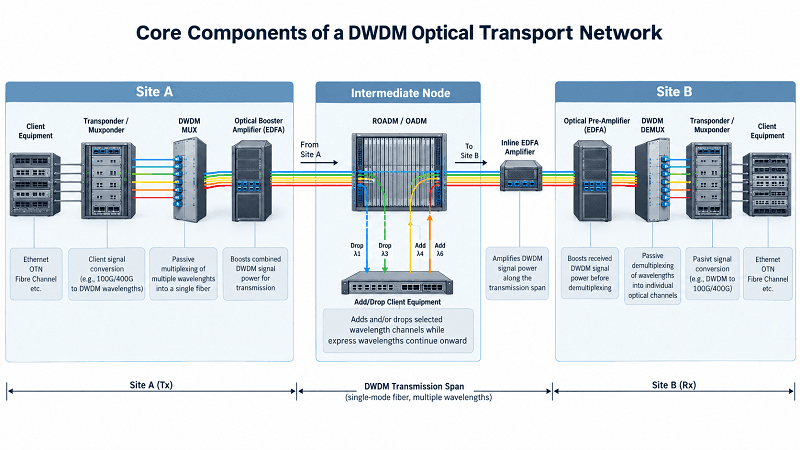
A DWDM system is built from a small set of building blocks. The table below summarizes what each one does, where it sits, and which FiberMall product line implements it.
| Component | Function | Network position |
| Transponder / muxponder | Converts client signals to assigned wavelengths | Terminal and add/drop nodes |
| MUX/DEMUX | Combines or splits wavelengths on one fiber | Terminal ends |
| OADM | Adds or drops selected wavelengths | Intermediate nodes |
| ROADM | Remotely reconfigures add/drop by wavelength | Reconfigurable ring/mesh nodes |
| EDFA / Raman amplifier | Boosts optical power in C/L band | Line and span ends |
| DWDM transceiver | Pluggable client or line optic at a fixed wavelength | Switch and router ports |
Transponders and Muxponders
A transponder receives a client signal and converts it into a suitable optical line signal for DWDM transmission.
Depending on its architecture, the transponder may convert electrical signals or short-reach optical signals into wavelength-specific DWDM interfaces.
Some transponders support 3R regeneration: reamplification, reshaping, and retiming.
These capabilities help restore signal characteristics and support transmission across different optical network segments.
However, the exact regeneration functions depend on the transponder architecture, signal-processing implementation, and line interface.
A muxponder performs a related function but combines multiple lower-rate client services into a higher-capacity transport signal.
For example, a muxponder may aggregate several Ethernet client interfaces into a single high-speed optical line interface.
This approach improves wavelength utilization when individual client services do not require a dedicated optical channel.
DWDM Multiplexers and Demultiplexers
A DWDM multiplexer combines multiple wavelength channels from separate input ports into one common optical output.
A demultiplexer performs the reverse operation, separating the composite DWDM signal into individual wavelength channels.
Passive DWDM mux/demux modules commonly use thin-film filters (TFFs) or arrayed waveguide gratings (AWGs) to manage wavelength routing.
Important specifications include:
- Channel spacing and wavelength range
- Number of supported channels
- Insertion loss
- Channel isolation
- Passband width and filter characteristics
- Return loss and polarization-dependent loss
Insertion loss is particularly important because it reduces the optical power available for transmission through the remaining network.
Lower insertion loss improves the available optical power budget, although system performance must also account for OSNR, filtering penalties, and other transmission impairments.
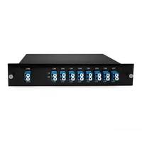
FiberMall’s DWDM MUX/DEMUX product category includes channel configurations for a range of network densities and fixed-grid applications. Exact channel counts, operating bands, and spacing options should be selected according to the relevant product specifications.
Add-Drop: OADM and ROADM
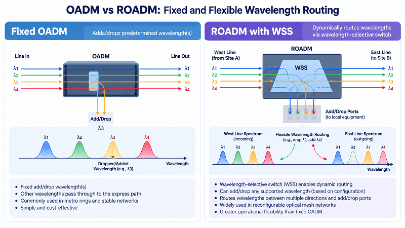
An optical add-drop multiplexer (OADM) inserts or removes selected wavelengths at an intermediate network site while allowing other wavelengths to pass through.
Fixed OADMs are commonly used in networks with stable wavelength assignments, including metro rings and point-to-point transport systems.
A reconfigurable optical add-drop multiplexer (ROADM) provides greater flexibility by allowing wavelength routing to be changed through remote configuration.
ROADMs commonly use wavelength-selective switches (WSSs) to direct optical channels between network directions and add/drop interfaces.
Advanced ROADM architectures may support three important capabilities:
- Colorless: Add/drop interfaces are not permanently assigned to specific wavelengths.
- Directionless: Supported wavelengths can be routed among different network directions.
- Contentionless: The architecture can accommodate identical wavelengths on different directions without internal add/drop wavelength contention, within the equipment’s design limitations.
These capabilities are often described as CDC ROADM features.
Not every ROADM supports all three functions. Actual wavelength routing flexibility depends on the WSS architecture, port configuration, and add/drop design.
ROADMs are widely used in optical mesh networks because they simplify wavelength provisioning, network expansion, and traffic restoration.
However, wavelength reconfiguration is not automatically hitless. Service continuity depends on the network architecture, protection mechanisms, and operational procedures.
For fixed wavelength add/drop requirements in metro networks, passive DWDM OADM modules remain a practical and cost-effective option.
Optical Amplifiers
Optical amplifiers increase the power of optical signals without performing optical-electrical-optical conversion.
Erbium-doped fiber amplifiers (EDFAs) are widely deployed in DWDM networks because they can amplify multiple optical channels simultaneously within their supported operating bands.
Common amplifier positions include:
- Booster amplifier: Installed near the transmitting end to increase optical launch power into the transmission fiber.
- Pre-amplifier: Installed before the optical receiver to improve the available received signal power.
- Inline amplifier: Installed along a fiber route to compensate for accumulated attenuation.
Inline amplifier spacing commonly falls within a range of approximately 60–100 km in conventional terrestrial deployments, although the actual distance depends on fiber loss, amplifier performance, optical power limits, and OSNR requirements.
Raman amplification provides another approach to extending optical reach.
Distributed Raman amplification uses the transmission fiber itself as part of the optical gain medium. It can improve effective noise performance and may be combined with EDFAs in long-haul systems.
However, optical amplification does not remove accumulated noise or fully restore the original signal quality.
A properly engineered DWDM system must balance optical power, amplifier noise, chromatic dispersion, fiber nonlinearities, and receiver requirements.
DWDM Transceivers and Client Optics
Not every DWDM connection requires a separate transponder shelf.
In suitable network architectures, a switch or router can use a wavelength-specific DWDM transceiver to connect directly to a compatible optical multiplexing system.
A DWDM transceiver emits light at a defined optical channel frequency, unlike a conventional grey optical module designed for a standard short-reach or fixed-wavelength interface.
DWDM transceivers can be divided into fixed-wavelength and tunable types.
| Type | Channel Behavior | Inventory Impact |
| Fixed DWDM transceiver | Operates on one specified DWDM channel | Multiple channel-specific SKUs may be required |
| Tunable DWDM transceiver | Supports configurable channels within its specified tuning range | Reduces the number of channel-specific spares |
| Grey transceiver + transponder | Uses a standard client interface connected to a DWDM line interface | Provides architectural flexibility but requires additional equipment |
Fixed-wavelength modules are useful in smaller or stable DWDM deployments where wavelength assignments rarely change.
Tunable DWDM transceivers allow operators to configure supported optical channels through the host platform or management interface.
However, tunable modules cannot necessarily operate on every channel across the entire C-band. Their supported frequency range, tuning granularity, transmission characteristics, and host compatibility depend on the specific module design.
Tunable transceivers can simplify inventory management, particularly in networks that require many different wavelength assignments.
Traditional DWDM transceivers are available in form factors such as SFP, SFP+, and XFP, while modern coherent implementations are offered in higher-density form factors such as QSFP-DD and OSFP.
For more information about optical module interfaces and compatibility considerations, see our SFP module guide.
Coherent DWDM and 400G/800G Transport
The biggest change in DWDM over the past decade is coherent detection. Older systems detected only the amplitude of light. Coherent systems detect both amplitude and phase, which lets a single wavelength carry far more data and travel much farther before it needs regeneration.
Coherent DWDM pairs advanced modulation with digital signal processing (DSP):
- DP-QPSK carries one 100G or 200G channel per wavelength with excellent reach.
- 16QAM and higher pack more bits per symbol for 400G and 800G, trading reach for capacity.
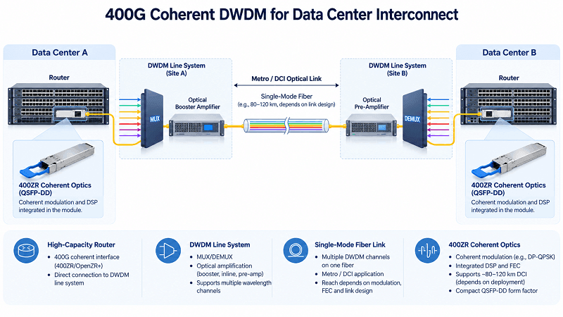
- 400ZR and OpenZR+ define compact, pluggable coherent modules that fit QSFP-DD and OSFP ports, so a router can light a DWDM wavelength directly without a separate transponder shelf.
This pluggable coherent approach is reshaping data center interconnect (DCI) and metro networks. A 400ZR module in a switch port can span 80-120 km over an amplified link and connect directly to the DWDM layer. That topologies let operators collapse transport shelves into the IP layer. The same optical layer still relies on the fundamentals above: the ITU grid, mux/demux, and amplification. Coherent optics simply put more bits on each wavelength. See our fiber optic networking guide for how the optical layer fits the wider stack.
DWDM Network Design and Link Budget
DWDM network planning requires more than confirming that sufficient optical power reaches the receiver.
A successful design must ensure both adequate received signal power and acceptable signal quality throughout the transmission path.
A link budget evaluates the optical power losses and gains between the transmitter and receiver.
For amplified coherent systems, engineers must also evaluate OSNR, nonlinear impairments, spectral filtering, and the required system margin.
The main factors include:
- Launch power: The optical power transmitted into the DWDM system, which varies according to the transceiver and line-system design.
- Span loss: Attenuation from fiber, connectors, splices, and other passive components. Typical C-band fiber attenuation is approximately 0.2 dB/km, although actual values depend on the fiber type and operating wavelength.
- Amplifier gain and noise figure: Amplifier gain compensates for optical attenuation, while amplifier noise contributes to OSNR degradation.
- Optical signal-to-noise ratio (OSNR): A key transmission quality metric that must satisfy the requirements of the receiver and coherent modulation format.
- Chromatic dispersion and PMD: Chromatic dispersion and polarization mode dispersion affect signal transmission. Coherent DSP can compensate for substantial chromatic dispersion, but residual impairments and system limits must still be considered.
- Nonlinear effects: Optical nonlinearities, including self-phase modulation, cross-phase modulation, and four-wave mixing, may affect high-capacity DWDM systems.
- System margin: Additional margin is required for aging, repairs, fiber degradation, and operating variations.
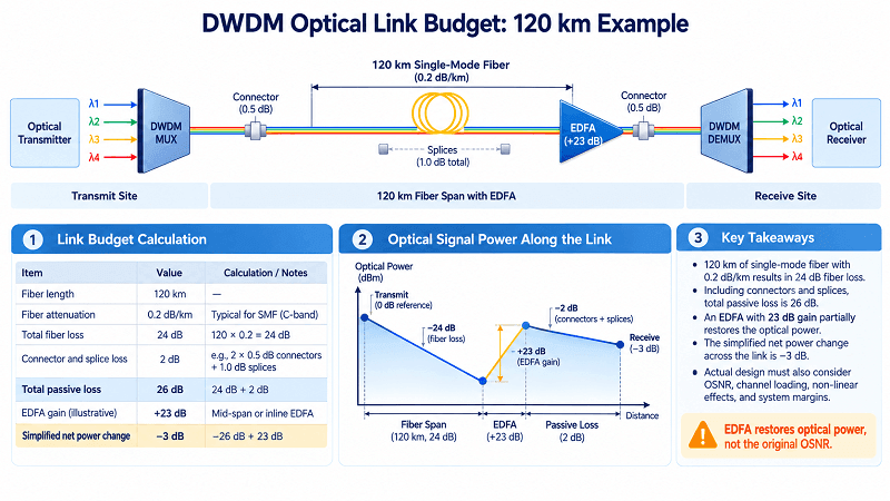
Example: 120 km DWDM Link Budget
Consider a 120 km single-mode fiber route operating in the C-band.
Assume the following illustrative parameters:
| Parameter | Value |
| Fiber length | 120 km |
| Fiber attenuation | 0.2 dB/km |
| Total fiber attenuation | 24 dB |
| Connector and splice loss | 2 dB |
| Total passive span loss | 26 dB |
| Illustrative amplifier gain | 23 dB |
| Illustrative amplifier noise figure | 5 dB |
The passive optical span loss is:
120 km × 0.2 dB/km + 2 dB = 26 dB
If an optical amplifier provides 23 dB of gain, the simplified net power change across the modeled passive loss and amplifier is approximately −3 dB.
This calculation is only an optical power illustration. It does not, by itself, demonstrate that the complete link meets the required performance.
The actual amplifier location, input power, output power, saturation characteristics, and per-channel power must be included in a detailed engineering design.
Optical amplifier gain can compensate for fiber attenuation, but it does not restore the original OSNR.
Each amplification stage contributes noise, while high optical launch powers may increase nonlinear transmission penalties.
For coherent 400G and 800G applications, a complete engineering analysis must consider the selected modulation and FEC modes, required OSNR or generalized signal-to-noise ratio (GSNR), filtering penalties, nonlinear effects, and receiver operating limits.
Two planning principles help improve reliability.
First, determine amplifier placement from actual span loss and optical performance requirements rather than applying a fixed distance rule.
Second, reserve sufficient design margin for component aging, network maintenance, and future expansion.
DWDM vs OTN and IPoDWDM
Two common approaches determine how client traffic is transported over a DWDM network.
Traditional optical transport architectures use transponders or muxponders, often incorporating Optical Transport Network (OTN) framing and switching functions.
IP over DWDM (IPoDWDM) integrates coherent optical transmission capabilities directly into compatible IP routers or switches, potentially reducing the need for separate transponder shelves.
These approaches are not mutually exclusive. A network can use integrated coherent IP interfaces in some segments while retaining OTN transport functions in others.
| Aspect | OTN + DWDM | IPoDWDM |
| Framing | Supports OTN framing based on ITU-T G.709 | Typically uses integrated coherent interfaces for direct IP/Ethernet transport |
| Equipment | Transponders, muxponders, and optional OTN switching | Routers or switches with coherent optical interfaces |
| Traffic grooming | Supports multi-service aggregation and sub-rate grooming | Primarily optimized for direct high-capacity connections |
| OAM | Rich transport-layer monitoring and maintenance features | Relies on integrated IP, Ethernet, and optical monitoring capabilities |
| FEC | OTN and optical line FEC functions, depending on architecture | Coherent line-side FEC, depending on interface specification |
| Latency | Depends on processing and switching architecture | May reduce latency by eliminating intermediate transport equipment |
| Best fit | Multi-service transport, grooming, and complex optical networks | High-capacity router interconnect and DCI |
OTN provides standardized transport framing, operations, administration, and maintenance (OAM), and traffic grooming capabilities.
These functions are valuable when multiple client services must share optical transport resources.
IPoDWDM can simplify the network by reducing standalone transport equipment and integrating coherent optical interfaces into the routing layer.
However, it does not automatically eliminate all OTN functions, nor does it guarantee lower end-to-end latency in every deployment.
Many network operators use both architectures, selecting the appropriate approach according to service requirements, operational complexity, cost, and existing infrastructure.
Testing and Troubleshooting DWDM Systems
DWDM commissioning and maintenance are essential for maintaining reliable optical transmission.
Common problems include incorrect optical power levels, insufficient OSNR, wavelength misalignment, excessive insertion loss, dirty connectors, and amplifier gain imbalance.
The following checks help isolate faults.
- Power verification: Measure per-channel optical power at appropriate test points and compare the readings against the design values. Uneven channel power may indicate filter loss, amplifier gain tilt, wavelength routing issues, or transmitter power differences.
- OSNR and BER testing: Evaluate optical signal quality and bit error performance against the relevant interface requirements. Low OSNR may result from accumulated amplifier noise, excessive attenuation, or incorrect power management.
- Loss-of-signal (LOS) alarms: Check whether the alarm affects one wavelength, one port, or multiple channels. A single-channel LOS may indicate a transceiver, connector, filter, or local path fault, while simultaneous failures across multiple channels may suggest a common fiber or equipment problem.
- Fiber cleaning: Contaminated optical connectors can introduce insertion loss and back-reflection. Follow an inspect-clean-inspect procedure before connecting optical interfaces.
- Amplifier gain tilt: Uneven gain across the optical band can cause substantial differences in channel power. Gain flattening and channel power equalization should be checked during commissioning and maintenance.
- Wavelength verification: Confirm that fixed or tunable modules are configured to the intended optical channels and that the mux/demux channel plan matches.
- Coherent performance monitoring: Where supported, review pre-FEC BER, corrected and uncorrectable error indicators, estimated signal quality metrics, and module alarms.
These checks help identify optical impairments before they cause significant service degradation.
Although DWDM channels are individually addressable, they share physical infrastructure and may also share amplifiers, ROADMs, and other optical components.
A practical troubleshooting procedure should isolate the issue by channel, network node, and fiber span.
Benefits of DWDM Technology
DWDM delivers three compounding advantages: capacity, cost efficiency, and reach.
Massive Capacity on Existing Fiber
Each wavelength is an independent channel, so capacity grows with the channel count. With modern high-rate optics, a 96-channel system in a 50 GHz plan can carry well over a terabit per second per fiber pair. It does so without new cable. Adding a wavelength is far cheaper and faster than trenching new fiber.
Lower Cost per Bit
DWDM spreads the cost of fiber, amplifiers, and shelters across many channels. Once the photonic layer is in place, incremental capacity costs only the new transceiver and channel filter. That economics is why operators favor DWDM for metro and data center interconnect, where fiber is precious and capacity demand keeps climbing.
Long Reach Without Regeneration
Because C-band channels can be amplified, DWDM spans reach hundreds of kilometers with only optical amplifiers. That reach removes the cost and latency of electrical regeneration, which matters most on long-haul and subsea-linked routes. The result is fewer active elements in the path and a simpler, more reliable network.
DWDM Applications and Use Cases
DWDM serves a wide range of networks. In telecom backbones, it carries the aggregate traffic of entire regions over long-haul and subsea routes. In metro networks, it connects central offices and data centers across a city on a shared fiber ring, using OADMs and ROADMs to add and drop wavelengths at each site.
Data center operators use DWDM for data center interconnect, linking campuses and metro sites at 100G, 400G, and 800G. AI and high-performance computing clusters push this further, driving dense 400G and 800G coherent links between GPU pods and storage. Broadband and access networks use WDM to share capacity into aggregation points.
What ties these cases together is a need to scale capacity on fiber that is already deployed. Whether the goal is a 400 km backbone span or an 80 km campus link, DWDM equipment provides the multiplexing, amplification, and transport hardware to get there.
DWDM Product Selection Guide
Matching equipment to the deployment keeps costs predictable. Start with the channel plan, then work outward through the photonic layer to the client optics.
| Deployment need | Recommended starting point |
| Small metro or access ring | 8-16 channel DWDM MUX/DEMUX, LGX or 1U rack |
| Metro or regional backbone | 40-48 channel MUX/DEMUX, fixed or ROADM |
| High-density long-haul | 96 channel 50 GHz MUX/DEMUX, C+L band |
| Intermediate add/drop site | Passive DWDM OADM or ROADM |
| Long spans | C/L-band EDFA plus Raman assist |
| Client-side colored optics | Fixed or tunable DWDM SFP/SFP+ |
| High-speed line links | 400ZR / OpenZR+ coherent QSFP-DD or OSFP |
FiberMall supplies the full chain, from passive mux/demux and OADM modules to amplifiers and DWDM transceivers. Because the products are designed to the same ITU grid, they interoperate with mainstream switch and router platforms. That single-source approach simplifies procurement and keeps the channel plan consistent across a deployment.
Frequently Asked Questions
What is DWDM equipment?
DWDM equipment is the hardware used to generate, combine, transmit, amplify, route, and separate wavelength channels over optical fiber.
Typical components include DWDM transceivers, transponders, multiplexers, demultiplexers, optical add-drop multiplexers, ROADMs, and optical amplifiers.
Together, these components allow many independent optical signals to share a common fiber infrastructure.
How many channels does DWDM support?
The number of DWDM channels depends on the available optical spectrum, channel spacing, and equipment design.
Traditional 100 GHz systems commonly support approximately 40 channels, while 50 GHz systems may support 80 or 96 channels using suitable C-band spectrum.
Flexible-grid systems allocate spectral slots according to the requirements of the optical signals rather than using one fixed channel width for every wavelength.
C+L-band deployments can provide additional wavelength capacity, but the total number of channels depends on the usable spectrum and selected spacing.
What is the difference between DWDM and CWDM?
DWDM uses relatively narrow optical channel spacing, commonly 50 GHz or 100 GHz in traditional fixed-grid systems.
CWDM uses 20 nm channel spacing and supports up to 18 standard wavelength channels.
CWDM is often preferred for lower-cost, lower-density short-reach applications.
DWDM is generally better suited to high-capacity metro, long-haul, and amplified optical transport networks.
How far can a DWDM signal travel?
DWDM transmission distance depends on fiber attenuation, modulation format, optical amplification, OSNR, and receiver performance.
Unamplified DWDM links may support distances ranging from short metro connections to longer spans, depending on the optical interfaces used.
With suitable optical amplification, DWDM systems can carry signals over hundreds of kilometers.
Some coherent long-haul systems support substantially greater distances, while higher-capacity modulation modes may require shorter reaches or additional regeneration.
There is no single maximum transmission distance that applies to all DWDM systems.
What is a DWDM transceiver, and how is it used?
A DWDM transceiver is an optical module designed to transmit and receive signals using wavelength channels compatible with a DWDM system.
Fixed-wavelength modules operate at a specified channel frequency.
Tunable DWDM transceivers allow supported channels to be configured through compatible host equipment.
These modules can connect switches, routers, or optical transport platforms to DWDM multiplexing systems.
A separate transponder may not be required when the host platform and optical interface support the selected transmission architecture.
Why is insertion loss important in DWDM systems?
Insertion loss represents the optical power reduction introduced by a component or connection.
DWDM multiplexers, demultiplexers, filters, connectors, and other passive components contribute to the total optical link loss.
Higher insertion loss reduces the optical power available at downstream network elements.
In amplified systems, additional loss may also increase the amplification requirements and affect the overall optical signal quality.
Selecting low-loss components helps preserve optical power margin and improve link design flexibility.
Does DWDM require new fiber?
Not necessarily.
DWDM can often be deployed over existing single-mode fiber infrastructure, provided the fiber characteristics and optical link conditions support the intended transmission system.
Before deployment, operators should evaluate fiber attenuation, connector quality, chromatic dispersion, polarization mode dispersion, and other relevant transmission impairments.
DWDM increases capacity by transmitting additional wavelengths over existing fiber, reducing the need for new fiber construction in many applications.
Conclusion
DWDM equipment transforms existing optical fiber into a scalable, high-capacity transport platform.
Multiplexers combine multiple wavelength channels, optical amplifiers extend transmission reach, and transceivers generate the optical signals carried through the network.
OADMs and ROADMs add wavelength-routing flexibility, while coherent 400G and 800G technologies enable higher capacity and improved spectral efficiency.
From metro access and regional backbone networks to high-capacity data center interconnects, DWDM provides a flexible foundation for modern optical communications.
The key principles are straightforward: channel spacing determines spectral allocation, the ITU-T G.694.1 grid provides standardized frequency planning, and optical link engineering determines achievable transmission performance.
Successful DWDM deployment requires more than matching wavelengths. Engineers must also consider equipment compatibility, optical power, OSNR, modulation format, FEC, and network architecture.
By selecting the right combination of DWDM components, operators can expand network capacity while making efficient use of existing fiber infrastructure.
Ready to build or expand a DWDM network? Explore FiberMall’s DWDM MUX/DEMUX modules, DWDM OADM solutions, and DWDM transceivers, or contact our optical networking engineers for assistance selecting equipment that matches your fiber infrastructure, channel plan, and transmission requirements.
Related Products:
-
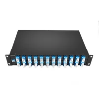
 DWDM MUX DEMUX 50GHZ 96CH (C15-C62) LC/UPC Dual Fiber 2U Rack
$6000.00
-
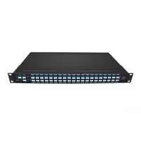
DWDM MUX DEMUX 40CH (C21-C60) LC/UPC Dual Fiber 1U Rack
$1100.00
-
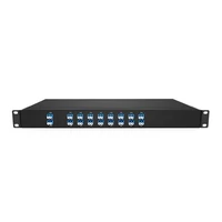
DWDM MUX DEMUX 16CH (C21-C36) with Monitor Port LC/UPC Dual Fiber 1U Rack
$800.00
-
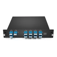
DWDM MUX DEMUX 8CH (C21-C28) with Express Port LC/UPC Dual Fiber LGX BOX
$500.00
-
DWDM MUX 8CH 16 Wavlengths (TX: C43/C45/C47/C49/C51/C53/C55/C57 RX: C44/C46/C48/C50/C52/C54/C56/C58) with MON Port LC/UPC Single Fiber LGX BOX
$450.00