Introduction
Data traffic is exploding with the widespread application of mobile Internet, the Internet of Things (IoT), and cloud computing. According to the data analysis given by the Ethernet Alliance, our demand for data transmission technology is at the 400Gbps stage, and it may develop towards 800Gbps or even 1.6Tbps in the future. The traditional data center cabling system makes it hard to meet the development of a high-speed rate, so the high-speed rate MPO pre-terminated system will be implemented more and more quickly.

To understand the practical application of the MPO pre-terminated system, we need to first understand the polarity of fiber transmission.
Fiber link polarity: that is, from the “transmit” of one end of the optical link to the “receive” of the other end;
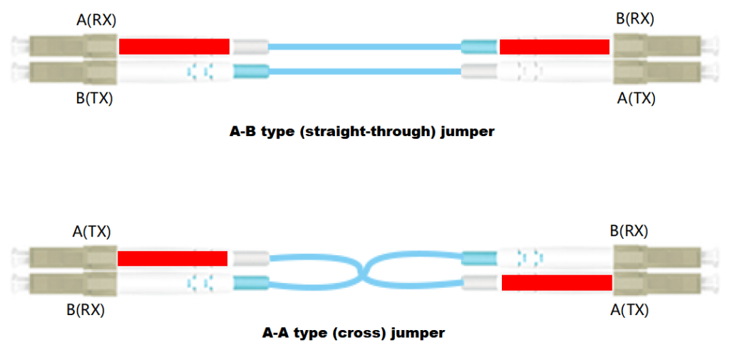
Fiber transmission uses the “transmit” and “receive” of transceivers to transmit information, and all methods use “duplex jumpers” to form fiber links. Maintaining the correct transmit-to-receive polarity through the cabling system is critical for the operation of the communication system. The TIA standard defines two different types of LC or SC duplex fiber jumpers to complete the end-to-end duplex connection:
A-B type (straight-through) jumper, A-A type (cross) jumper.
MPO-MPO Straight-through Cable (Type-A)
Type A (Straight-through): The fiber arrangement positions at both ends of the MPO-MPO patch cord are the same, that is, one end’s 1 corresponds to the other end’s 1, and one end’s 12 corresponds to the other end’s 12. As shown in the figure below.
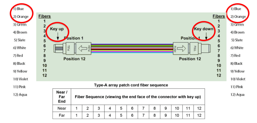
The fiber arrangement positions at both ends are the same. To ensure the principle of “transmit” at one end of the optical link to “receive” at the other end, the standard duplex A-A type patch cord is used at one end of the link, and the A-B type patch cord is used at the other end.
MPO-MPO Fully Crossed Cable (Type-B)
Type B (Fully Crossed): The fiber arrangement positions at both ends of the MPO-MPO patch cord are opposite, that is, one end’s 1 corresponds to the other end’s 12, and one end’s 12 corresponds to the other end’s 1. As shown in the figure below.
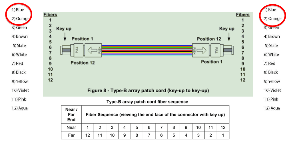
The fiber arrangement positions at both ends are opposite. To ensure the principle of “transmit” at one end of the optical link to “receive” at the other end, the standard duplex A-A type patch cord is used at both ends of the link (or the standard duplex A-B type patch cord is used at both ends).
MPO-MPO Pair Crossed Cable (Type-C)
Type C (Pair Crossed): The MPO-MPO patch cord is crossed by adjacent pairs of fibers, that is, one end’s fiber 1 corresponds to the other end’s 2, and one end’s fiber 12 is 11 at the other end. As shown in the figure below.
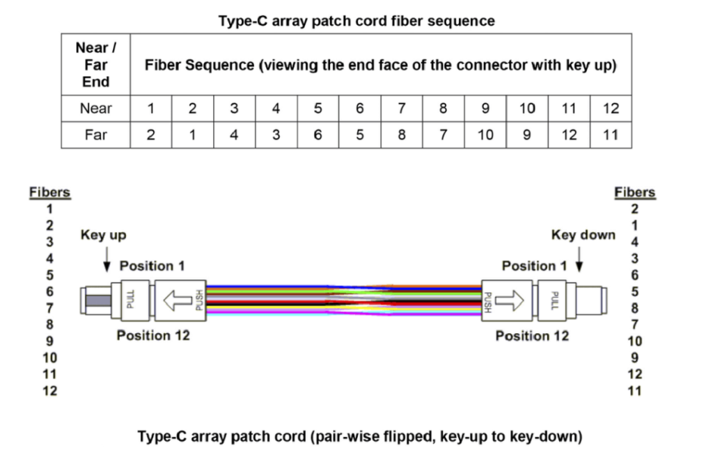
The fiber arrangement positions at both ends are opposite. To ensure the principle of “transmit” at one end of the optical link to “receive” at the other end, the standard duplex A-A type patch cord is used at both ends of the link (or the standard duplex A-B type patch cord is used at both ends).
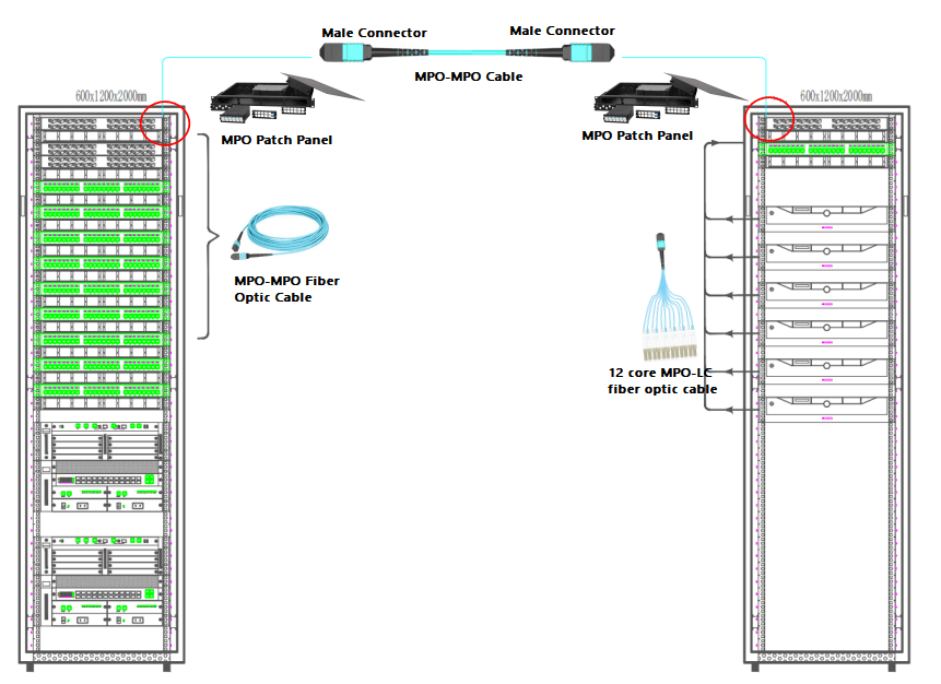
Practical Applications
Common pre-terminated products include:
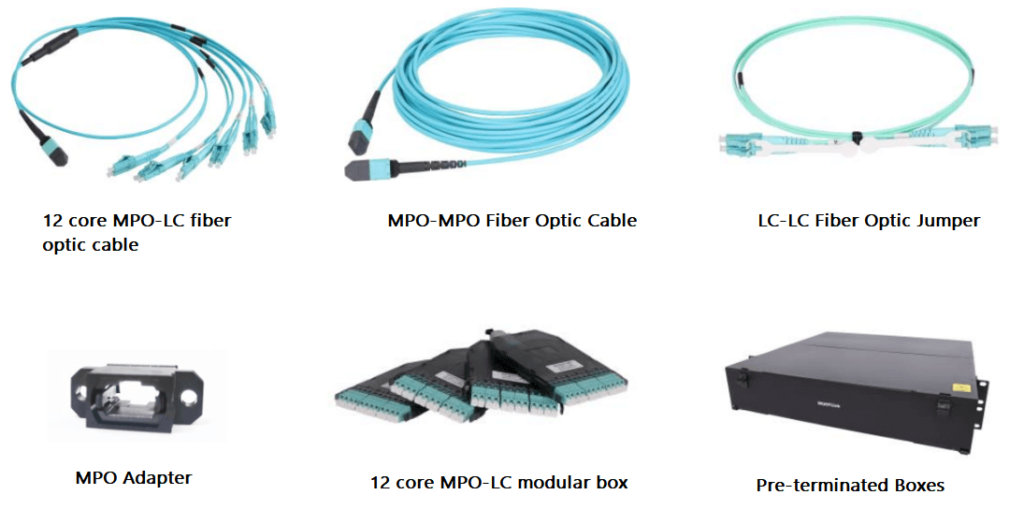
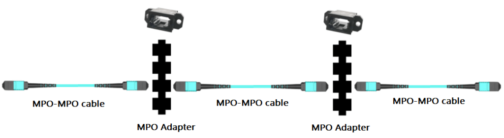
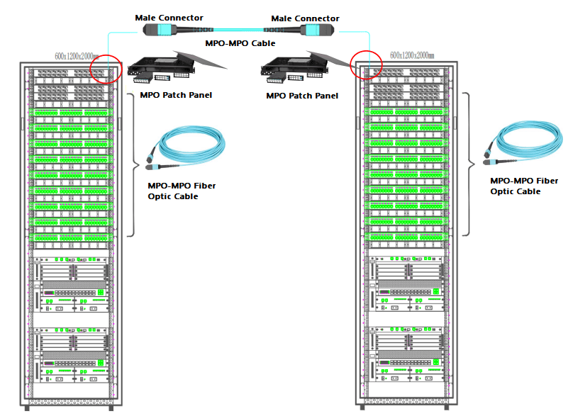
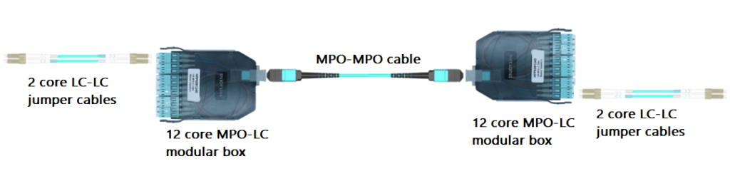
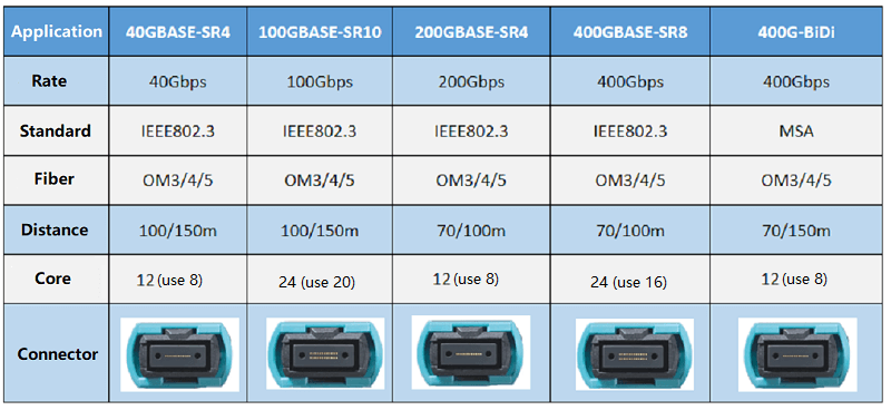
Links with MPO interfaces at both ends
MPO to MPO interface, which can mainly support Ethernet transmission applications such as 40G SR4, 100G SR4, 200G SR4, 400G SR8, 400G SR16, and 400G BiDi.
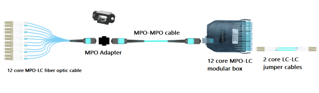
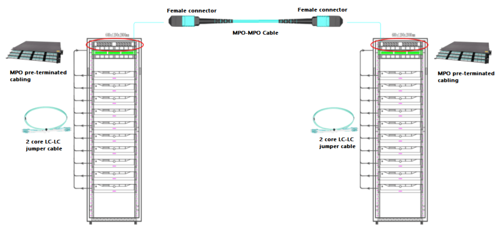
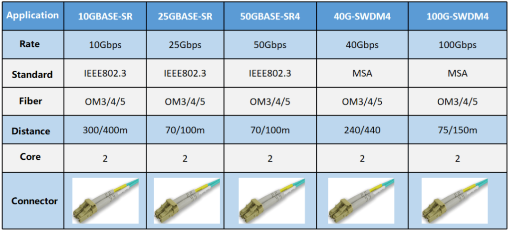
Links with LC interfaces at both ends
2LC to 2LC interface, which can mainly support Ethernet transmission applications such as 10GBASE-SR, 25GBASE-SR, 40G-SWDM4, 100G-BiDi, and 100G-SWDM4.
Type 1:
Type 2:
Type 3:
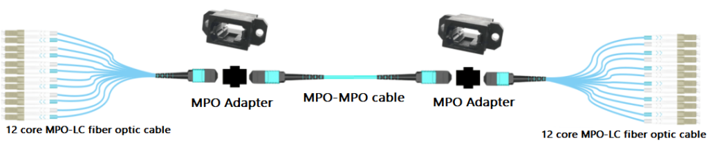
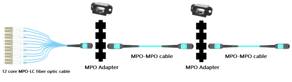
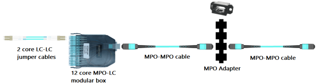
Links with MPO interface at one end and LC interface at the other end
MPO to 2LC interface, which can mainly support Ethernet transmission applications such as 40GBASE-SR4 to 10GBASE-SRx4, 100GBASE-SR4 to 25GBASE-SRx4, 100GBASE-SR10 to 10GBASE-SRx10.
Type 1:
Type 2:
Summary
Different models support different protocols, transmission applications, and rates. The actual connection situation of the project should be used to select different connection models, connection levels, and MPO male (female) head types. ISO/IEC TR 11801-9908 gives a selection guide for multimode fiber cabling systems, which suggests that the category of multimode fiber cabling systems should be based on the type and length of network applications deployed. OM3 and OM4 can support all network 10/40/100/200/400G application types, and OM5 can support longer transmission distances when using short-wave division multiplexing technology (such as 400G SR4.2). Common application types are shown in the figure below:
Related Products:
-
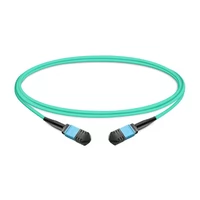
 1m (3ft) 12 Fibers Low Insertion Loss Female to Female MPO Trunk Cable Polarity B LSZH OM3 50/125 Multimode Fiber
$32.00
1m (3ft) 12 Fibers Low Insertion Loss Female to Female MPO Trunk Cable Polarity B LSZH OM3 50/125 Multimode Fiber
$32.00
-
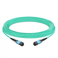
5m (16ft) 16 Fibers Female to Female MPO Trunk Cable Polarity B LSZH OM4 50/125 Multimode Fiber APC
$89.00
-
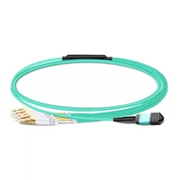
1m (3ft) MPO UPC Female to 4 LC UPC Duplex OM3 50/125 Multimode Fiber Breakout Cable, 8 Fibers, Type B, LSZH, Aqua
$20.00
-
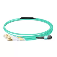
1m (3ft) MPO UPC Female to 6 LC UPC Duplex OM3 50/125 Multimode Fiber Breakout Cable, 12 Fibers, Type B, Elite, LSZH, Aqua
$26.00
-
QSFP28-100G-SR4 100G QSFP28 SR4 850nm 100m MTP/MPO MMF DDM Transceiver Module
$40.00
-
Q28-100G23-BX10 100G QSFP28 BIDI TX1271nm/RX1331nm PAM4 Single Lambda LC SMF 10km DDM Optical Transceiver Module
$500.00
-
QSFP-DD-200G-SR8 2x 100G QSFP-DD SR8 850nm 70m/100m OM3/OM4 MPO-16(APC) MMF Optical Transceiver Module
$350.00
-
QSFP-DD-400G-SR8 400G QSFP-DD SR8 PAM4 850nm 100m MTP/MPO OM3 FEC Optical Transceiver Module
$149.00