If you follow the optical module industry, you will often hear the phrase “LPO needs to remove the DSP chip.” Why is this? To answer this question, we first need to clarify two core concepts: what LPO is and the role of DSP in optical modules. This will explain why LPO aims to “remove” the DSP. This article explains the technical logic and industrial background to help you understand it better.
What are LPO and DSP?
LPO (Linear-drive Pluggable Optics)
LPO is a new type of optical module technology solution that has emerged in the field of optical communications in recent years. It belongs to the “pluggable optical module” category (similar to common QSFP and OSFP form factors).
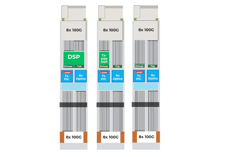
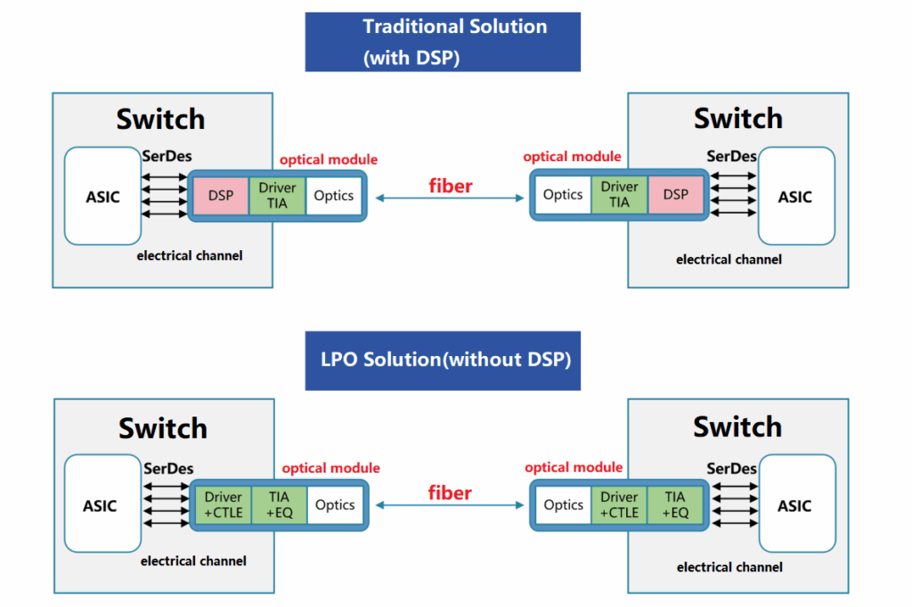
Core Feature: It uses Linear Drive technology to replace the traditional “Digital Signal Processing (DSP)” chip in optical modules. By simplifying the signal processing link, it reduces power consumption, latency, and cost.
DSP (Digital Signal Processor)
In traditional high-speed optical modules (such as 200G/400G/800G), the DSP is one of the core chips. Its main functions are:
- Signal Compensation: Performs digital algorithmic compensation for distortion (such as dispersion, noise, and non-linear loss) generated during signal transmission.
- Encoding/Decoding: Implements signal mapping and demodulation for high-order modulation (such as PAM4, 16QAM).
- Clock Recovery: Synchronizes data clocks at both the transmitting and receiving ends to ensure transmission accuracy.
- Equalization and Error Correction: Uses adaptive equalization algorithms to cancel out channel interference and reduce the bit error rate.
Why LPO Needs to Remove the DSP Chip
The original intention of LPO design is to solve the pain points caused by DSP in traditional optical modules. Therefore, it is necessary to “remove” or “bypass” the DSP chip. This can be understood from four dimensions: power consumption, latency, cost, and heat dissipation.
Power Consumption: DSP is a High-Power Core, LPO Needs to “Reduce Power”
- In traditional high-speed optical modules (e.g., 400G), the power consumption of the DSP chip is extremely high (accounting for about 30%-50% of the total power). For example, the DSP power consumption of a 400G optical module may reach 15-20W, causing the power consumption of the entire module to exceed 30W.
- LPO uses linear drive circuits (such as linear Transimpedance Amplifiers [TIA] and linear Laser Driver [LD Driver]) to directly handle the conversion of electrical and optical signals, eliminating the digital computing aspect of the DSP. This can reduce the total power consumption of the optical module by 30%-50% (e.g., dropping from 30W to under 15W). This is crucial for high-density deployment scenarios like data centers, where low power consumption means fewer cooling requirements, lower electricity costs, and higher rack utilization rates.
Latency: DSP’s “Digital Processing” Introduces Extra Delay
- DSP requires digital processing such as sampling, quantization, and algorithmic compensation. This process introduces microsecond or even nanosecond-level latency (depending on algorithm complexity). In latency-sensitive scenarios such as High-Performance Computing (HPC) and AI training/inference, increased latency can affect overall system efficiency.
- LPO completes signal amplification and conversion directly through linear drive circuits, eliminating the digital processing steps of DSP. Latency can be reduced by more than 50% (e.g., from microseconds to sub-microseconds), making it more suitable for low-latency applications.
Cost: DSP is the “High-Priced Component” of Optical Modules
- High-end DSP chips (such as solutions from Broadcom and Inphi) are expensive, accounting for 20%-40% of the total cost of the optical module. For example, the DSP cost for a 400G optical module can be hundreds of dollars. By removing the DSP, the Bill of Materials (BOM) cost of the optical module can be reduced by 20%-30%, which is significant for cost control in large-scale deployments (such as data center interconnects).
Heat Dissipation: High DSP Power Consumption Aggravates Module Heating
- High-power DSPs cause the internal temperature of optical modules to rise, requiring additional heat sinks or fans, which increases module volume and design complexity. The low-power characteristic of LPO reduces thermal pressure, allowing for more compact module designs (such as thinner packaging) to meet the requirements of high-density switch/router ports.
Technical Challenges and Solutions for “Removing DSP”
LPO does not simply “chop off” the DSP; instead, it compensates for the missing functions of the DSP through Linear Drive Circuits + System-Level Optimization.
The Core Challenges Are:
- Signal Distortion Compensation: Traditional DSPs compensate for signal distortion via algorithms. LPO must rely on the hardware design of linear drive circuits (such as high-precision TIA, LD Driver) and the cooperation of upstream equipment (such as Switch ASICs), sharing the compensation task through “Pre-distortion” or “Forward Error Correction (FEC).”
- Noise Suppression: DSP algorithms can suppress noise. LPO needs to optimize analog circuit design (e.g., low-noise components, shielding layers) to reduce noise impact.
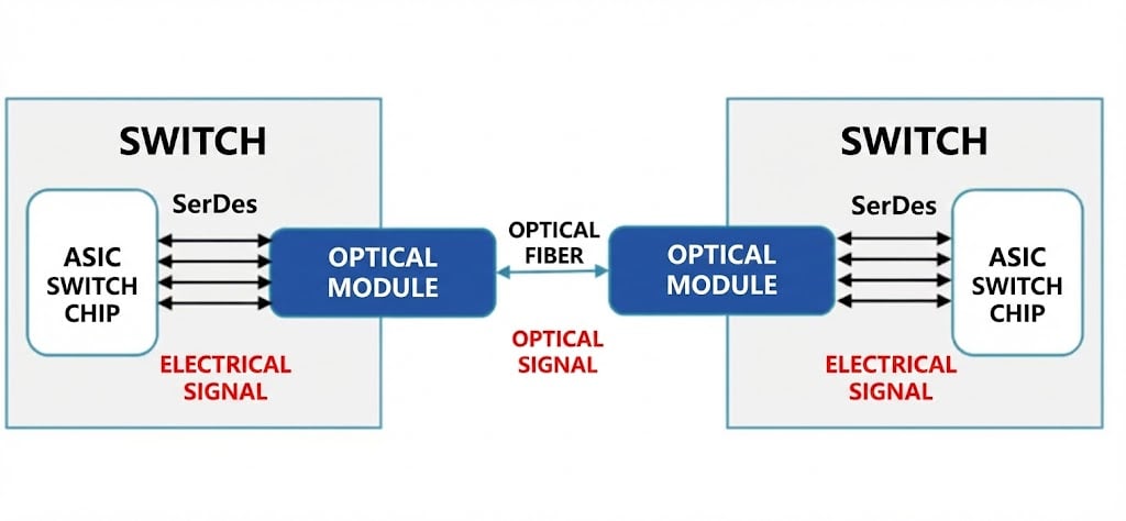
- Compatibility: LPO needs to work synergistically with the Switch/Router interfaces (such as SerDes) to ensure signal format matching.
A Layman’s Explanation: How Linear Drive “Fills the Gap”
If the above is still hard to understand, let’s break it down into the simplest language: Why can the optical module still work after removing the DSP, and how does the linear drive circuit exactly “take over”?
Reviewing the Role of DSP in Optical Modules
Imagine the optical module as a “Courier”:
- Data leaves the switch as a string of electrical signals (0s and 1s).
- The optical module converts it into optical signals (using laser on/off to represent 0 and 1) and sends it into the fiber.
- The receiving optical module converts the optical signal back to an electrical signal for the device at the other end.
- During this process, the electrical signal gets “deformed” (distorted), mixes with noise, or suffers timing misalignment due to line quality, temperature changes, and fiber quality.
DSP acts like a “High-Level Repairman”: When it receives a deformed signal, it uses mathematical algorithms to repair it to its original state (compensating dispersion, reducing noise, adjusting the clock, correcting errors). The problem is: The DSP is great at its job, but it consumes a lot of power, has high latency, and is expensive.
LPO’s Idea: Can we do without this repairman, or have other stages do the work in advance, thereby saving on the repairman?
What Does the Linear Drive Circuit Do?
Linear drive circuits are pure hardware circuits (without complex digital calculations), including:
- Linear Laser Driver (LD Driver): Responsible for directly amplifying the electrical signal and driving the laser to emit light.
- Linear Transimpedance Amplifier (TIA): Responsible for converting the received weak optical signal back into an electrical signal and amplifying it.
Their characteristic is “Linearity”: The output signal changes proportionally to the input signal size, without adding a bunch of mathematical operations itself. You can understand it as: The DSP was an “Intelligent Repairman,” while the Linear Drive is a “Precise Mover” + “Pre-prepared Auxiliary Measures.” It relies on hardware precision and collaborative work to reduce signal errors.
How Linear Drive Circuits “Fill the Gap” of DSP Functions
DSP’s core functions are mainly four types: Signal Compensation, Encoding/Decoding, Clock Recovery, and Equalization/Error Correction. LPO bypasses or shares these tasks in the following ways:
(1) Signal Compensation — Relies on “Upstream Pre-distortion” and “Hardware Precision”
- Upstream Pre-distortion: Before the signal enters the optical module, the Switch’s ASIC (Application Specific Integrated Circuit) has already performed a pre-distortion (twisting) on the signal via software/hardware, so that it exactly cancels out the distortion encountered during subsequent transmission. Thus, when the optical module receives it, the signal is basically accurate and doesn’t need the DSP to calculate it again.
- Hardware Precision Improvement: Linear drive circuits use higher precision components (low-noise lasers, low-drift amplifiers) to minimize distortion during conversion, reducing the amount that “needs repair” at the source.
Analogy: Previously, the courier (DSP) received a broken box and repaired it himself; now, the box is reinforced before shipping (Pre-distortion + High-precision hardware), so the courier just moves it and doesn’t need to fix it.
(2) Encoding/Decoding — Uses Simpler or Fixed Modulation
- DSP can handle very complex modulation (like PAM4, 16QAM), but LPO generally uses simpler modulation (like NRZ or simple PAM4) because complex modulation requires massive digital computation, exactly hitting the DSP’s weak point (or rather, necessitating its use).
- Alternatively, in short-distance scenarios (inside data centers), low-order modulation is used directly because the signal itself is less prone to error, so complex decoding by a DSP isn’t needed.
Analogy: Previously, the repairman could fix various complex combination locks; now, we send “clear code” packages—you just read them upon receipt, no decoding needed.
(3) Clock Recovery — Relies on “Fixed Rate + External Synchronization”
- DSP can extract clock information from the signal to align the rhythm of receiving and transmitting ends.
- LPO switches to fixed-rate transmission (e.g., both sides agree on the rate beforehand) and uses an external clock source (provided by the switch) for direct synchronization, skipping the step of “guessing” the clock from the signal.
Analogy: Previously, the repairman guessed the beat by listening to the sound. Now, everyone uses the same metronome directly, no guessing required.
(4) Equalization and Error Correction — Relies on FEC Sharing
- DSP uses adaptive equalization algorithms to adjust signals in real-time.
- LPO hands this task over to Forward Error Correction (FEC)—adding redundant check codes to the data. After the receiving end detects an error, it uses these codes to automatically correct it. FEC can be completed by the switch or other chips, without needing the DSP in the optical module to calculate it in real-time.
Analogy: Previously, the repairman fixed damages while receiving the package; now, the package comes with spare parts (FEC), so if something is broken, you just replace it with the spare, no temporary repairs needed.
The Effects and Costs of Linear Drive
(1) Effects:
- Power Saving: Eliminated the high power consumption of DSP.
- Reduced Latency: Less time spent on digital computation.
- Reduced Cost: DSPs are expensive.
- Reduced Thermal Pressure.
(2) Costs (Trade-offs):
- Higher Link Quality Requirements: Because there is no DSP for real-time repair, the signal must be as “clean” as possible.
- Suitable for Short Distances/Low Noise: Best for environments like data center cabinets; not suitable for long distances or harsh channels.
- Requires Upstream/Downstream Cooperation: Switches and fibers need optimization, otherwise performance will degrade.
Summary: The Essence of LPO “Removing DSP”
The essence of “removing the DSP chip” in LPO is to reconstruct the signal processing link of the optical module through linear drive technology. It achieves this by relying on “cleaning the signal in advance + high-precision hardware + upstream/external sharing of repair tasks.”
This solution requires sacrificing some “signal robustness in complex scenarios” as a trade-off to gain the advantages of low power consumption, low latency, and low cost. This makes it more suitable for short-distance, high-bandwidth, low-latency scenarios (such as internal data center interconnects), whereas for long-distance, high-noise scenarios (such as cross-city transmission), traditional optical modules with DSP remain irreplaceable.
Related Products:
-
 LOSFP-800G-2FR4L LPO OSFP 2x400G FR4 PAM4 1310nm 2km DOM Dual Duplex LC SMF Optical Transceiver Module
$3500.00
LOSFP-800G-2FR4L LPO OSFP 2x400G FR4 PAM4 1310nm 2km DOM Dual Duplex LC SMF Optical Transceiver Module
$3500.00
-
LOSFP-800G-DR8D 800G LPO OSFP DR8 PAM4 1310nm 500m DOM Dual MTP/MPO-12 SMF Optical Transceiver Module
$1800.00
-
LOSFP-800G-SR8 LPO OSFP 8x100G SR8 PAM4 850nm MTP/MPO-16 50m OM4 MMF FEC Optical Transceiver Module
$1100.00
-
LOSFP-800G-SR8D LPO OSFP 8x100G SR8 PAM4 850nm 50m DOM Dual MPO-12 MMF Optical Transceiver Module
$1000.00
-
LQSFP-DD-800G-2FR4L LPO QSFP-DD800 2x400G FR4 PAM4 CWDM4 2km DOM Dual Duplex LC SMF Optical Transceiver Module
$1800.00
-
LQSFP-DD-800G-DR8D 800G LPO QSFP-DD800 DR PAM4 1310nm 500m DOM Dual MPO-12 SMF Optical Transceiver Module
$1500.00
-
LQSFP-DD-800G-SR8 800G SR8 LPO QSFP-DD 850nm 50m OM3 MMF MPO-16 Optical Transceiver Module
$1300.00
-
LQSFP-DD-800G-SR8D 800G SR8 LPO QSFP-DD 850nm 50m OM3 MMF 2xMPO-12 Optical Transceiver Module
$1300.00
-
LQSFP112-400G-DR4 400G LPO QSFP112 DR4 PAM4 1310nm 500m MTP/MPO-12 with KP4 FEC Optical Transceiver Module
$1200.00
-
LQSFP112-400G-SR4 400G LPO QSFP112 SR4 PAM4 850nm 50m MTP/MPO-12 OM3 FEC Optical Transceiver Module
$800.00