In the fast-paced realm of high-speed optical communications, major optical module manufacturers are leveraging 4-channel optical sampling oscilloscopes to enhance TX testing efficiency for 400G, 800G, and 1.6 T modules. However, due to the architectural differences between 4-channel and single-channel TX testing, extra attention to details is essential. Otherwise, even after purchasing a 4-channel oscilloscope, it might only function as a single-channel device, impacting production expansion and delivery schedules.
At FiberMall, we specialize in providing cost-effective optical-communication products and solutions tailored for global data centers, cloud computing environments, enterprise networks, access networks, and wireless systems. Renowned for our leadership in AI-enabled communication networks, we’re your ideal partner for high-quality, value-driven 1.6 T optical module solutions. For more details, visit our official website or contact our customer support team.
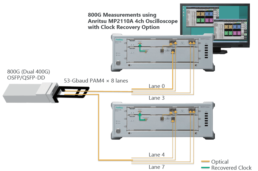
TX Optical Eye Parallel Testing Architecture for 1.6 T Modules
The diagram below illustrates a typical architecture using two 4-channel Anritsu MP2110A oscilloscopes equipped with built-in OCRUs for parallel testing of 8 optical eyes in an 800G optical module. The module’s internal DSP drives the lasers to produce 8 lanes of optical signals under test, patterned as PRBS/SSPRQ. The first MP2110A’s OCRU extracts the clock signal from Lane 0 and provides trigger signals for the optical eyes of Lanes 0-3, while the second MP2110A’s OCRU extracts from Lane 4 and triggers Lanes 4-7. In actual production line setups, optical switch matrices can be utilized for more flexible configurations, improving oscilloscope utilization rates.
Configuring Optical Modules for Synchronous Output in 1.6 T Testing
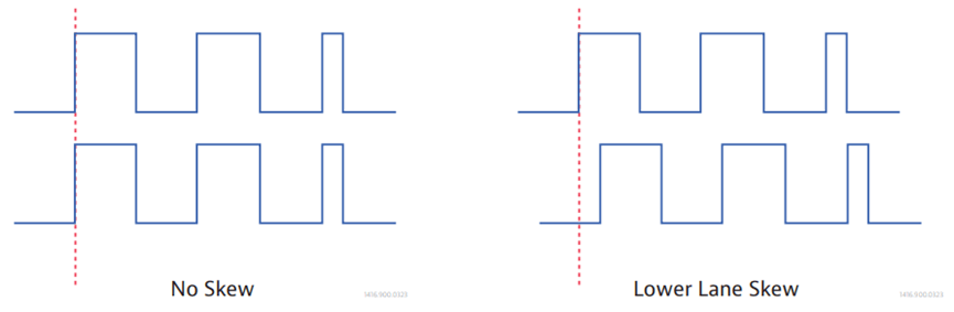
We first need to understand skew, which is the inevitable timing difference between optical channels in multi-channel parallel operation scenarios. As shown in the diagram below, the left side represents the ideal case where skew=0, while the right side shows a certain amount of skew.
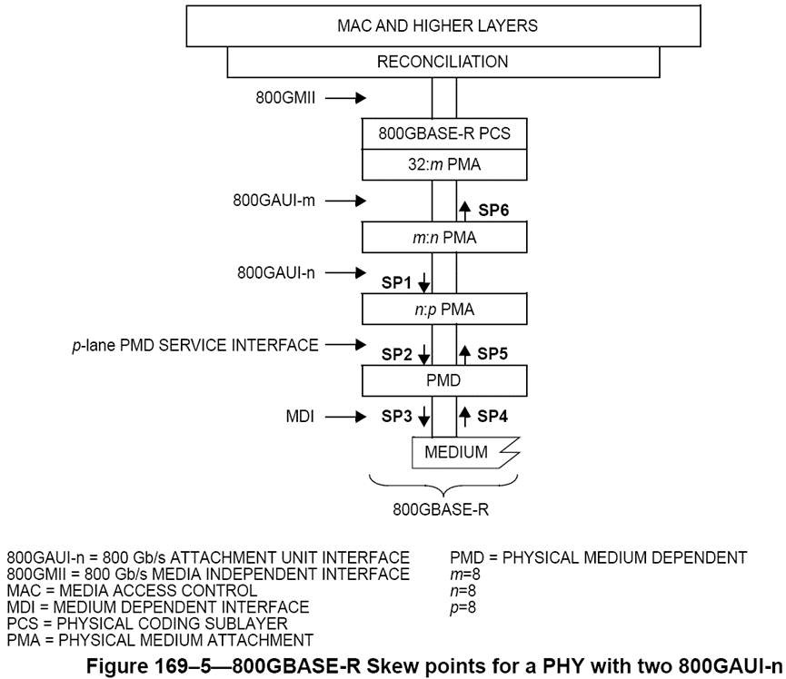
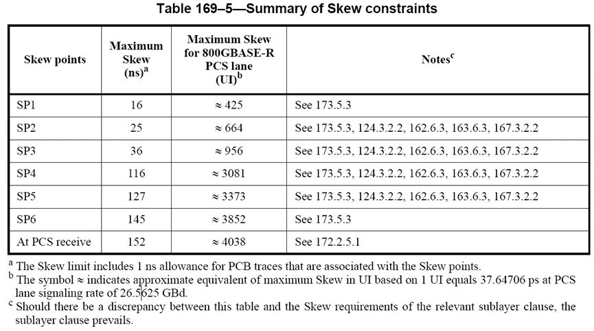
The IEEE 802.3 standard allows for a certain amount of skew between channels. This standard defines the links between PMA/PMD/Medium as SP1~SP6 and specifies the absolute upper limits and standard deviations for skew on each path. It can be observed that as the signal travels longer paths, the skew upper limit and standard deviation increase accordingly. VIAVI has a dedicated section explaining how to perform skew tolerance testing using ONT.
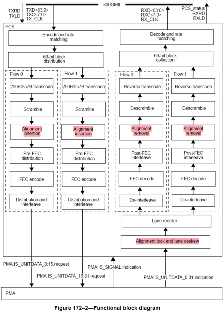
As shown in the diagram below, optical modules perform deskew at the PCS layer using Alignment Markers on the RX side. We’ll hold off on details here—the author will explain further in the upcoming article “1.6 T Ethernet Physical Layer Analysis.” It’s important to note that unlike bit error rate testing, TX optical eye diagram testing shares a single trigger across 4 channels. This results in extra jitter introduced by SP3 skew on the lanes other than the one extracting the clock, potentially causing the eye diagrams for those lanes to fail to appear.
Fortunately, DSP manufacturers have considered this and developed a TX multi-lane synchronous output mode to minimize skew between channels while outputting the required PRBS/SSPRQ patterns. In this mode, the DSP can even provide an additional divided clock signal to the oscilloscope for triggering, which can save the cost of OCRUs. If optical module manufacturers find that in a 4-channel oscilloscope setup, only the lane extracting the clock shows a normal eye diagram while the other three exhibit extremely high jitter, there’s no need to worry about major module issues. First, use the 4-channel oscilloscope as a single-channel device to confirm if the eye diagrams recover normally when each of the other three lanes extracts its own clock. After verifying that the module’s TX optical eyes are fine in the single-channel scenario, contact the DSP manufacturer to update the firmware to support multi-lane synchronous output of optical signals.
Oscilloscope Triggering in 1.6 T Parallel Testing
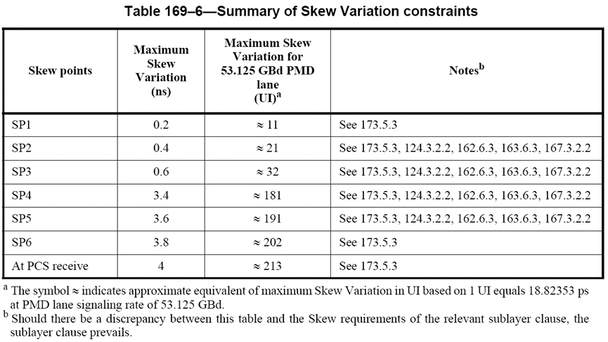
Even when the DSP operates in synchronous output mode, it’s impossible to guarantee that skew between TX optical lanes is reduced to zero. Due to differences in circuit designs among DSP manufacturers, the stability of the synchronous output mode itself and the residual skew can vary. We cannot simply deem optical modules with significant residual skew in synchronous output mode as defective based on 4-channel oscilloscope eye diagram results, as the IEEE 802.3 standard has very loose requirements for skew (32UI skew variation for 53.125Gbaud SP3). Ultimately, we must evaluate the module’s quality based on post-FEC bit error rate and sensitivity test results on the switch. (The author believes these are the core indicators determining optical module performance.) The ultimate purpose of TX optical eye diagram testing is to serve the post-FEC bit error rate and sensitivity tests; we cannot sacrifice good products for the sake of using 4-channel parallel testing to improve efficiency.
Parallel testing with 4 channels introduces additional jitter due to skew compared to single-channel scenarios, placing greater pressure on the oscilloscope’s triggering. Whichever oscilloscope manufacturer has stronger filtering capabilities for this type of jitter will measure eye diagram quality closer to single-channel results in 4-channel scenarios and can accommodate DSP chips with larger skew. Optical module manufacturers must thoroughly validate the degradation in eye diagram quality for their TX optical scheme in 4-channel versus single-channel scenarios before procurement, ensuring it is within tolerance before finalizing the decision.
Why FiberMall Excels in 1.6 T Optical Module Solutions
By meticulously addressing these aspects of TX parallel testing for 800G and 1.6 T optical modules—from architecture and skew management to synchronous configurations and triggering challenges—manufacturers can achieve optimal production efficiency without compromising on quality or reliability.
FiberMall is committed to delivering innovative, cost-effective solutions that empower your optical-communication infrastructure. Whether you’re enhancing AI-enabled networks or scaling data center operations, our expertise ensures reliable performance. Visit our website for more insights, or reach out to our team for personalized support.
Related Products:
-
 NVIDIA MMS4A00 (980-9IAH1-00XM00) Compatible 1.6T OSFP DR8D PAM4 1311nm 500m IHS/Finned Top Dual MPO-12 SMF Optical Transceiver Module
$2600.00
NVIDIA MMS4A00 (980-9IAH1-00XM00) Compatible 1.6T OSFP DR8D PAM4 1311nm 500m IHS/Finned Top Dual MPO-12 SMF Optical Transceiver Module
$2600.00
-
NVIDIA Compatible 1.6T 2xFR4/FR8 OSFP224 PAM4 1310nm 2km IHS/Finned Top Dual Duplex LC SMF Optical Transceiver Module
$3100.00
-
NVIDIA MMS4A00 (980-9IAH0-00XM00) Compatible 1.6T 2xDR4/DR8 OSFP224 PAM4 1311nm 500m RHS/Flat Top Dual MPO-12/APC InfiniBand XDR SMF Optical Transceiver Module
$3600.00
-
0.5m (1.6ft) NVIDIA Compatible 1.6T OSFP-RHS to OSFP-RHS Passive Direct Attached Cable
$465.00
-
OSFP-1.6T-4FR2 1.6T OSFP 4FR2 PAM4 1291/1311nm 2km SN SMF Optical Transceiver Module
$22400.00
-
OSFP-1.6T-2FR4 1.6T OSFP 2xFR4 PAM4 2x CWDM4 2km Dual Duplex LC SMF Optical Transceiver Module
$22400.00
-
OSFP-1.6T-DR8D+ 1.6T OSFP DR8D+ PAM4 1311nm 2km Dual MPO-12 SMF Optical Transceiver Module
$18000.00
-
OSFP-1.6T-DR8+ 1.6T OSFP DR8+ PAM4 1311nm 2km MPO-16 SMF Optical Transceiver Module
$18000.00
-
OSFP-1.6T-DR8D 1.6T OSFP DR8D PAM4 1311nm 500m Dual MPO-12 SMF Optical Transceiver Module
$2600.00
-
OSFP-1.6T-DR8 1.6T OSFP DR8 PAM4 1311nm 500m MPO-16 SMF Optical Transceiver Module
$12600.00
-
OSFP-XD-1.6T-4FR2 1.6T OSFP-XD 4xFR2 PAM4 1291/1311nm 2km SN SMF Optical Transceiver Module
$15000.00
-
OSFP-XD-1.6T-2FR4 1.6T OSFP-XD 2xFR4 PAM4 2x CWDM4 2km Dual Duplex LC SMF Optical Transceiver Module
$20000.00