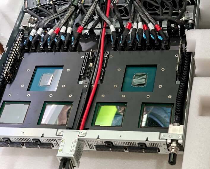
Next-generation AI chips like NVIDIA’s GB200 are pushing the boundaries of performance. But this immense power comes at a cost: staggering heat generation. A single GB200 chip package consumes up to 2700 W of power. With such high power in such a compact space, traditional air-cooling systems simply can’t keep up. The only way to maintain these chips’ cooling is through advanced liquid cooling technology.
The Numbers Behind the GB200 Cooling Challenge
To understand the solution, we must first delve into the problem. The heat produced by the GB200 isn’t just high—it’s extremely concentrated. This is known as heat flux density.
The chip generates a heat flux exceeding 50W/cm², equivalent to producing 50 W of heat in an area the size of a small fingernail. In certain hotspot areas, the heat flux can even surge to 150W/cm². If not controlled, this heat can quickly damage the chip. Therefore, the chip’s temperature rise (Tc) must typically be kept below 40°C, while the GPU itself requires even stricter limits—below 30°C.
Meeting these figures requires a cooling system with two key features:
- Extremely low thermal resistance (below 0.03°C/W). This means the cooling plate can efficiently remove heat from the chip.
- Low flow resistance (no more than 20kPa). This ensures the coolant can easily pass through the plate without needing powerful, energy-consuming pumps.
Inside the Cold Plate: Structure and Flow Physics
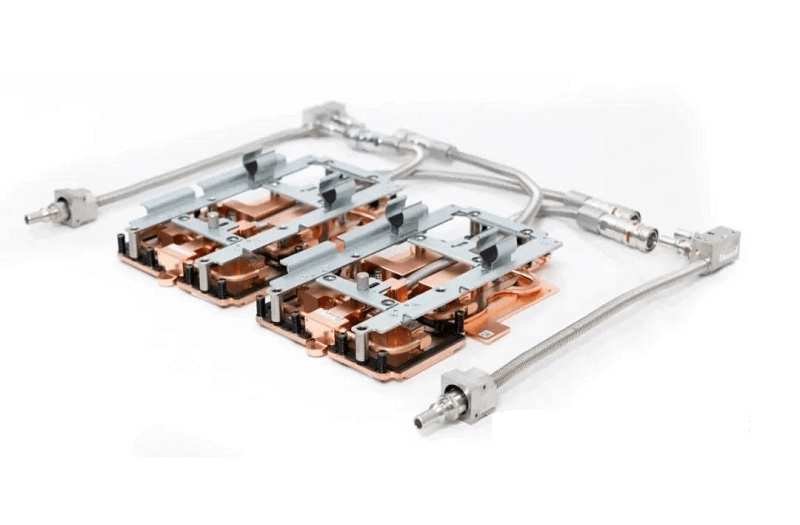
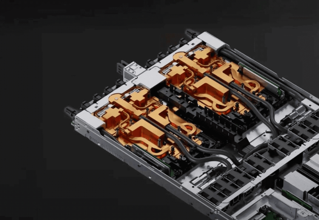
To achieve these impressive numbers, engineers use a special design called a microchannel cold plate, typically manufactured using a skived fin process (also known as the skiving process).
Microchannel Structure Using Skived Fins
The cooling plate is usually made of copper, an excellent thermal conductor (thermal conductivity of 385W/mK). Then, special tools are used to directly skive thin fins from the copper base. This forms a series of tiny parallel channels.
- Fin thickness (t) is generally ≤0.5mm.
- Spacing between fins (P) is also ≤0.5mm.
- Fin height (L) is typically ≥3mm.
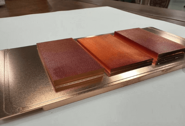
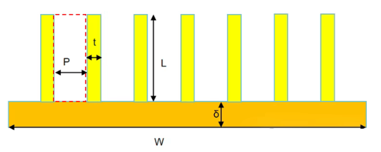
These minuscule dimensions create a massive internal surface area, which is crucial for absorbing heat into the liquid coolant flowing through the channels.
The structure of the microchannels is critical. The relationship between fin height (L) and spacing (P) determines how the liquid flows.
Understanding the Internal Flow Channels
The way liquid flows in these tiny channels is vital. Engineers use some key formulas to analyze this.
First, calculate the channel’s hydraulic diameter (Dh), which represents the effective size for fluid flow in the channel. The formula is:
Dh = 2(PL)/(P+L)*
Since the fin height (L) is much greater than the spacing (P), and the L/P ratio is usually over 15, the formula simplifies to: Dh ≈ 2P. This tells us that the effective channel size is directly related to the tiny spacing between fins.
Next, engineers use the Reynolds number (Re) to determine the flow type:
Re = ρ * V * Dh / μ
Where ρ is fluid density, V is velocity, and μ is viscosity. For a typical cold plate, the flow velocity (V) is usually less than 0.1m/s. Calculations show the Reynolds number (Re) is less than 2000. This confirms the flow is steady and predictable, known as laminar flow.
How to Improve Cold Plate Performance
Based on this knowledge, engineers know exactly what adjustments are needed to enhance cooling plate performance. There are two main goals:
- Reduce Flow Resistance
To make the liquid flow more easily, engineers can:
- Reduce the flow velocity (V) between the fins.
- Shorten the length of the fins along the flow direction.
- Increase Convective Heat Transfer
To make the plate cooling more effective, they need to increase the heat transfer coefficient (h). An interesting finding is that for this laminar flow, velocity (V) has little impact on “h”. Therefore, they have two other options:
- Increase the liquid’s thermal conductivity (k) by selecting a more effective coolant.
- Reduce the equivalent hydraulic diameter (Dh), which essentially means making the channels smaller and tighter.
By applying these precise principles and calculations, engineers can design and fine-tune efficient liquid cooling plates. This meticulous work is crucial for the future of AI, ensuring powerful chips like the GB200 can reach their full potential without overheating.
GB200 Liquid Cooling Plate Specifications
| Item | Content |
| Platform | GB200 |
| Type | Grace Blackwell Superchip |
| Architecture | 2xBlackwell GPU + Grace CPU |
| TDP | 2700W (2x1200W GPU + 300W CPU) |
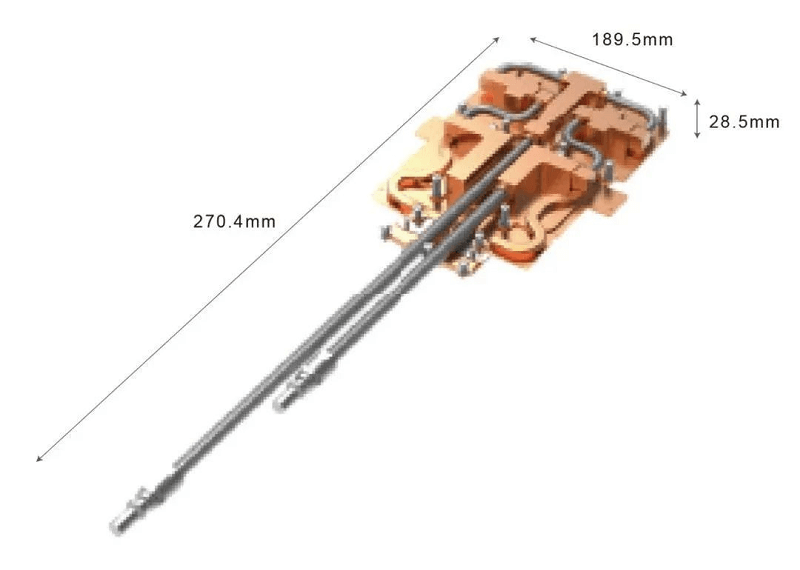
| Liquid Cooling Component Size | 189.5×270.4×28.5mm (WxHxD) |
| Cold Plate Component Weight | 2.9KG |
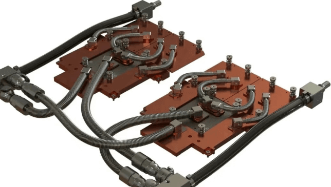
| Coolant | PG25 |
| Quick Connector | CEJN or CPC UQD04 |
| Liquid Cooling Tube Material | Stainless Steel or EPDM |
| Inlet Temperature | 45℃ |
| Flow Rate | 1.8 LPM |
| Fluid Resistance | < 20kPa |
| Thermal Resistance | Extremely low, below 0.03°C/W |
| Heat Flux Density | Exceeding 50W/cm², reaching 150W/cm² in some areas |
| Temperature Rise Limit | Chip temperature below 40°C, GPU temperature below 30°C |
FiberMall is a specialist provider of optical-communication products and solutions, committed to delivering cost-effective offerings to global data centers, cloud computing environments, enterprise networks, access networks, and wireless systems. Renowned for its leadership in AI-enabled communication networks, FiberMall is an ideal partner if you’re seeking high-quality, value-driven optical-communication solutions.
Related Products:
-
 Q112-400GF-MPO1M 400G QSFP112 SR4 MPO-12 Female Plug Pigtail 1m Immersion Liquid Cooling Optical Transceivers
$1950.00
Q112-400GF-MPO1M 400G QSFP112 SR4 MPO-12 Female Plug Pigtail 1m Immersion Liquid Cooling Optical Transceivers
$1950.00
-
Q112-400GM-MPO1M 400G QSFP112 SR4 MPO-12 Male Plug Pigtail 1m Immersion Liquid Cooling Optical Transceivers
$1950.00
-
Q112-400GF-MPO3M 400G QSFP112 SR4 MPO-12 Female Plug Pigtail 3m Immersion Liquid Cooling Optical Transceivers
$1970.00
-
Q112-400GM-MPO3M 400G QSFP112 SR4 MPO-12 Male Plug Pigtail 3m Immersion Liquid Cooling Optical Transceivers
$1970.00
-
Q112-400GF-MPO60M 400G QSFP112 SR4 MPO-12 Female Plug Pigtail 60m Immersion Liquid Cooling Optical Transceivers
$2025.00
-
Q112-400GM-MPO60M 400G QSFP112 SR4 MPO-12 Male Plug Pigtail 60m Immersion Liquid Cooling Optical Transceivers
$2025.00
-
OSFP-400GF-MPO1M 400G OSFP SR4 MPO-12 Female Plug Pigtail 1m Immersion Liquid Cooling Optical Transceivers
$1950.00
-
OSFP-400GM-MPO1M 400G OSFP SR4 MPO-12 Male Plug Pigtail 1m Immersion Liquid Cooling Optical Transceivers
$1950.00
-
OSFP-400GF-MPO3M 400G OSFP SR4 MPO-12 Female Plug Pigtail 3m Immersion Liquid Cooling Optical Transceivers
$1970.00
-
OSFP-400GM-MPO3M 400G OSFP SR4 MPO-12 Male Plug Pigtail 3m Immersion Liquid Cooling Optical Transceivers
$1970.00
-
OSFP-400GF-MPO60M 400G OSFP SR4 MPO-12 Female Plug Pigtail 60m Immersion Liquid Cooling Optical Transceivers
$2025.00
-
OSFP-400GM-MPO60M 400G OSFP SR4 MPO-12 Male Plug Pigtail 60m Immersion Liquid Cooling Optical Transceivers
$2025.00
-
OSFP-800G85F-MPO60M 800G OSFP SR8 MPO-12 Female Plug Pigtail 60m Immersion Liquid Cooling Optical Transceivers
$2400.00
-
OSFP-800G85M-MPO60M 800G OSFP SR8 MPO-12 Male Plug Pigtail 60m Immersion Liquid Cooling Optical Transceivers
$2400.00
-
OSFP-800G85F-MPO5M 800G OSFP SR8 MPO-12 Female Plug Pigtail 5m Immersion Liquid Cooling Optical Transceivers
$2330.00
-
OSFP-800G85M-MPO5M 800G OSFP SR8 MPO-12 Male Plug Pigtail 5m Immersion Liquid Cooling Optical Transceivers
$2330.00
-
OSFP-800G85F-MPO1M 800G OSFP SR8 MPO-12 Female Plug Pigtail 1m Immersion Liquid Cooling Optical Transceivers
$2250.00
-
OSFP-800G85M-MPO1M 800G OSFP SR8 MPO-12 Male Plug Pigtail 1m Immersion Liquid Cooling Optical Transceivers
$2250.00