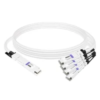
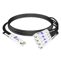
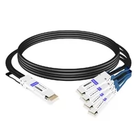
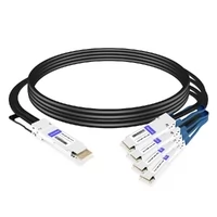
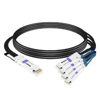
You connect a 400G-to-4×100G breakout cable to a high-density Ethernet switch, configure the interfaces, and check the transceiver diagnostics. The optical power readings appear normal, yet only some of the four 100G sub-ports establish a link. Others remain down, while active links may report CRC errors or FEC-related faults.
Although cable contamination and physical-layer defects should not be ruled out, these symptoms can also result from incorrect port channelization, incompatible transceiver applications, lane-mapping errors, or mismatched Forward Error Correction (FEC) settings.
In AI data centers and high-performance computing (HPC) networks, successful 400G breakout operation requires more than connecting the appropriate cable. The switch ASIC, host electrical interface, transceiver, breakout configuration, and remote 100G devices must support a compatible end-to-end operating mode.
This guide explains how 400G-to-4×100G breakout works, examines four common causes of sub-port failures, and provides a practical troubleshooting checklist for identifying configuration and physical-layer problems.
Related reading: Our complete QSFP breakout cable guide for 400G/800G AI data centers covers cable selection, including DAC, AOC, AEC, and fiber breakout solutions.
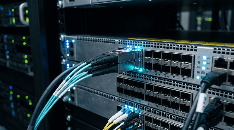
What Actually Changes When You Break Out 400G into 4×100G
In a conventional 100G Ethernet connection, a single logical interface carries one 100G link. Depending on the Ethernet PHY, that link may use four 25G NRZ lanes, two 50G PAM4 lanes, or one 100G PAM4 lane.
A 400G Ethernet port, however, may use either eight 50G PAM4 electrical lanes or four 100G PAM4 electrical lanes. The supported configuration depends on the switch ASIC, host interface, and transceiver generation.
To operate a supported 400G port as four independent 100G interfaces, the switch must perform port channelization, commonly called breakout or port splitting.
This operation creates four logical 100G interfaces from one physical 400G port, subject to the platform’s breakout capabilities.
| Parameter | Native 400G Mode | 4×100G Breakout Mode |
| Host electrical lanes | Typically 8×50G PAM4 or 4×100G PAM4 | Divided into four supported 100G lane groups |
| Logical interfaces | One 400G Ethernet interface | Four independent 100G Ethernet interfaces |
| CMIS application | Supported native 400G application, where applicable | Compatible breakout application, if required and supported |
| FEC | Determined by the 400G PHY | Determined by each 100G PHY and platform configuration |
| Link establishment | One 400G Ethernet link | Four independently operating 100G links |
| Speed configuration | Native 400G mode | Supported 4×100G breakout profile with appropriate sub-port settings |
Table 1 — Native 400G vs. 4×100G breakout: changes to logical interfaces, lane allocation, and operating profiles.
Host Lanes vs. Sub-Port Index
For a 400G interface based on 8×50G PAM4 electrical lanes, each 100G breakout sub-port typically uses two host lanes.
A representative host-lane mapping is shown below.
| Sub-Port | Host Lanes Used |
| Sub-port 1 (:1) | Lane 0 + Lane 1 |
| Sub-port 2 (:2) | Lane 2 + Lane 3 |
| Sub-port 3 (:3) | Lane 4 + Lane 5 |
| Sub-port 4 (:4) | Lane 6 + Lane 7 |
Table 2 — Example 4×100G host-lane mapping for an 8×50G PAM4 electrical interface.
For a 400G interface using 4×100G PAM4, each 100G sub-port may instead correspond to one 100G electrical lane.
Importantly, logical sub-port numbering does not necessarily follow the same physical lane assignment on every switch platform. The actual mapping must be verified against the switch vendor’s port-breakout documentation.
Furthermore, electrical lane mapping and optical lane mapping are not always identical. Optical transceivers may use internal signal processing, multiplexing, or lane conversion.
Therefore, a breakout cable should never be selected based solely on the host electrical lane count.

Root Cause 1: The Breakout Command Was Never Applied
One of the first checks when troubleshooting a 400G breakout connection is whether the switch has actually enabled the required breakout mode.
Installing a 400G QSFP-DD or OSFP module, or connecting a 400G-to-4×100G breakout cable, does not automatically guarantee that the switch will create four 100G interfaces.
If the breakout configuration has not been applied, the switch typically retains the physical port as one logical 400G interface.
Consequently, the expected 100G sub-ports may not appear in the interface configuration, even though the cable and connected hardware are physically present.
The link may remain down because the configured host mode does not match the connected breakout topology.
Figure 1 — Failure chain when the required breakout profile is not configured.
400G transceiver or breakout cable installed → Switch remains in native 400G mode → Four 100G logical sub-ports are not created → Breakout links cannot operate as intended → Link Down or missing sub-port interfaces.
Fix: Verify that the switch supports 4×100G breakout on the selected physical port, then apply the appropriate breakout profile using the platform-specific command.
For example, a switch may provide commands such as port breakout, interface breakout, or a hardware breakout profile. The exact syntax varies by operating system and hardware platform.
After enabling breakout mode:
- Confirm that four 100G logical interfaces have been created.
- Configure or verify the required speed and FEC settings.
- Check whether breakout affects adjacent physical ports or shared hardware resources.
- Verify that the connected transceiver or cable supports the selected breakout configuration.
Some switch platforms also impose restrictions on supported module types, adjacent port availability, or breakout combinations.
On Cisco, NVIDIA, and other high-density Ethernet platforms, consult the relevant hardware documentation before applying breakout changes to production ports.
Root Cause 2: FEC Conflict — KP4 vs. Clause 91 RS-FEC
Forward Error Correction (FEC) is essential for maintaining reliable Ethernet transmission over high-speed electrical and optical links.
However, different 100G Ethernet PHYs can use different FEC schemes.
A mismatch between the FEC settings supported or required by the two ends of a connection may prevent the link from establishing or cause unstable operation.
Two Reed-Solomon FEC codes commonly encountered in 100G Ethernet environments are RS(544,514) and RS(528,514).
Although both are Reed-Solomon codes, they have different codeword structures and are not directly interchangeable.
| FEC Code | Common Name | Code Rate Overhead* | Error Correction Capability | Typical Applications |
| RS(544,514) | KP4 FEC | ~5.84% | Up to 15 symbols per codeword | 100G PAM4 PHYs and other specified high-speed Ethernet PHYs |
| RS(528,514) | RS-FEC, often associated with Clause 91 | ~2.72% | Up to 7 symbols per codeword | Selected 100G NRZ PHYs, including 100GBASE-CR4/KR4 and SR4 implementations |
Table 3 — Comparison of two common Reed-Solomon FEC codes used in Ethernet systems.
Overhead is calculated relative to the 514 data symbols. The applicable IEEE clause and FEC requirements depend on the specific PHY.
A common troubleshooting mistake is to assume that every 100G interface uses the same FEC mode.
For example, a 100GBASE-DR1 optical connection uses a different physical-layer architecture from a conventional 100GBASE-SR4 connection.
The required FEC configuration must therefore be determined from the actual Ethernet PHY, not simply from the nominal 100G data rate.
After enabling 4×100G breakout, some switch platforms automatically select the required FEC mode. Others allow or require explicit per-sub-port configuration.
Fix: Verify the supported FEC mode on both ends of every 100G connection.
For each breakout sub-port:
- Identify the Ethernet PHY and transceiver type.
- Check the FEC mode supported or required by the local and remote devices.
- Confirm whether the switch selects FEC automatically or requires manual configuration.
- Compare FEC status and error counters on both link endpoints.
For supported 100GBASE-DR1, FR1, and LR1 connections using 100G PAM4 signaling, RS(544,514) is the relevant FEC code.
For applicable legacy 100G NRZ PHYs, RS(528,514) may be used.
Do not disable FEC unless the specific PHY and both connected devices explicitly support operation without it.
Operational Tip: Monitor pre-FEC BER, corrected FEC codewords, uncorrectable FEC codewords, and CRC counters where available.
Corrected FEC codewords do not necessarily indicate a failed link. However, persistent or increasing uncorrectable errors require further investigation.
If a link is already Up but experiences CRC errors, also examine cable signal integrity, optical power margin, transceiver compatibility, and host-side SerDes performance rather than assuming FEC mismatch is the only possible cause.
Root Cause 3: CMIS AppSel Never Re-Instantiated (Page 10h)
Modern QSFP-DD and OSFP transceivers commonly use the Common Management Interface Specification (CMIS) to communicate supported applications and operating states to the host.
A CMIS-managed module may advertise multiple application profiles, depending on its hardware design and firmware implementation.
These profiles can describe different combinations of host electrical interfaces, media interfaces, and supported operating modes.
However, support for multiple applications does not mean that every 400G transceiver supports 4×100G breakout.
The host must select an application that is both advertised by the module and supported by the switch platform.
For CMIS implementations using a staged data-path control mechanism, the host can configure application selections through Page 10h and apply supported changes through the relevant data-path initialization controls.
The resulting data-path state and active application can then be checked through CMIS diagnostics.
A failure can occur when the switch has been configured for 4×100G breakout, but the module remains in an incompatible application or data-path state.
Possible symptoms include:
- One or more breakout sub-ports remain Down.
- The transceiver is detected, but the requested application is not active.
- The module reports a data-path initialization or configuration problem.
- The switch reports an unsupported transceiver or breakout mode.
Fix: Verify the module’s advertised applications, selected application, and active data-path state.
A recommended troubleshooting sequence is:
- Confirm that the transceiver supports the requested breakout topology.
- Check whether the switch has selected a compatible CMIS application.
- Verify the active application and data-path state through transceiver diagnostics.
- Reapply the breakout configuration or restart the affected port if recommended by the vendor.
- Consider a module reset only when supported troubleshooting procedures require it.
A hardware reset should not be treated as the default method for every AppSel change.
Also note that CMIS application management is implementation-dependent. Passive DAC cables and some active cable assemblies do not use the same application-selection workflow as programmable optical transceivers.
Root Cause 4: MPO-12 → 4×LC Polarity (Method B)
For optical breakout connections using an MPO-to-LC fanout cable, correct fiber mapping is essential.
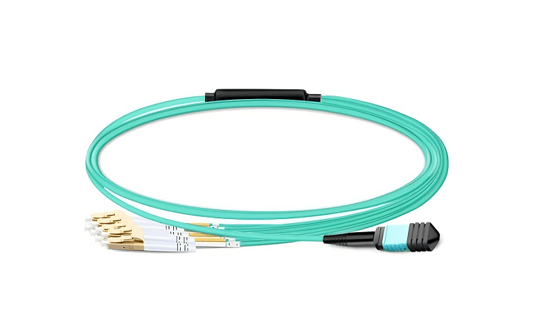
A supported 400G parallel-optics transceiver may connect to four independent 100G optical transceivers through an appropriately designed MPO-12-to-4×LC duplex breakout cable.
However, incorrect connector polarity, key orientation, or fiber mapping can prevent individual optical channels from establishing the expected connection.
A common mistake is assuming that every MPO-12-to-4×LC breakout cable follows the same polarity arrangement.
In practice, the required cable configuration depends on the transceiver’s optical-lane assignment, connector interface, and end-to-end cabling topology.
Incorrect polarity or fiber mapping can result in:
- Transmit and receive fibers not being connected correctly.
- Optical channels being routed to the wrong receiving positions.
- One or more breakout links remaining Down.
- Unexpected differences between measured optical power and interface status.
Type-A and Type-B MPO connectivity methods describe different fiber-position mappings. Neither should be assumed universally correct for every 400G or 800G breakout application.
The correct configuration must be verified against the optical module and cable assembly specifications.
Fix: Check the complete end-to-end optical path.
- Verify the 400G transceiver’s connector type and fiber-position assignment.
- Confirm the MPO connector key orientation and required polish type.
- Check the MPO-to-LC breakout cable’s internal fiber mapping.
- Verify that each LC duplex leg connects to the intended 100G transceiver.
- Inspect and clean connector end faces according to IEC 61300-3-35 inspection criteria and the applicable cleaning procedures.
For example, 400GBASE-DR4 optical breakout commonly uses an MPO-12 parallel single-mode interface with four transmit and four receive fibers.
When connecting to compatible 100GBASE-DR1, FR1, or LR1 transceivers, the fiber mapping and optical specifications must be verified.
A compatible MPO-to-LC fanout cable provides the required physical fiber distribution, but it cannot resolve an incompatible optical PMD or unsupported switch breakout mode.
The speed 100g Trap
A frequent configuration mistake is assuming that setting a 400G interface to 100G automatically creates four independent 100G interfaces.
For example, an engineer may apply a command such as speed 100g to the parent physical interface and expect the switch to activate a 4×100G breakout connection.
However, interface speed configuration and port channelization are different operations.
Changing the configured speed of a parent interface does not necessarily divide its physical resources into four logical sub-ports.
Depending on the platform, the command may be rejected, may change the operating speed of a single interface, or may be unsupported for the installed module.
It should not be interpreted as a universal breakout command.
The correct procedure is to:
- Verify that the physical port supports 4×100G breakout.
- Apply the appropriate port-breakout profile.
- Confirm that the four logical 100G interfaces have been created.
- Configure or verify speed and FEC settings for each sub-port.
- Verify the operational status of all four links.
Always use the switch vendor’s documented breakout commands rather than assuming that a speed command automatically enables channelization.
Field Checklist: 6 Steps to Diagnose a 400G Breakout Failure
When one or more 100G sub-ports remain Down, troubleshoot systematically from the switch configuration to the physical connection.
Figure 2 — Decision tree for troubleshooting 400G-to-4×100G breakout failures.
Start: One or more 100G breakout links are Down
→ Are four logical 100G sub-ports present?
- No → Verify platform support and apply the correct 4×100G breakout profile.
- Yes → Continue to lane mapping and compatibility checks.
→ Are the transceiver and breakout cable compatible?
- No → Select a supported module and cable combination.
- Yes → Continue to FEC and application checks.
→ Are FEC settings and module application states correct?
- No → Correct the supported FEC or CMIS application configuration.
- Yes → Verify optical polarity, signal quality, and physical connectivity.
→ Do all four links establish and operate without persistent errors?
- No → Inspect error counters, fiber mapping, signal integrity, and vendor logs.
- Yes → Validate stability under production traffic.
1. Check Whether the Sub-Ports Exist
Display the switch’s interface configuration and verify that four 100G logical interfaces have been created.
If the expected sub-ports do not exist, check the port’s breakout capabilities and apply the required 4×100G profile.
Do not proceed with optical troubleshooting until the intended logical interfaces are present.
2. Verify the Lane Map
Compare the switch’s supported lane assignment with the breakout cable and transceiver specifications.
Identify whether the host operates using 8×50G or 4×100G PAM4 and confirm that the platform supports the corresponding 4×100G configuration.
For active cables and optical modules, verify the supported breakout topology rather than relying only on electrical lane counts.
3. Align FEC per Sub-Port
Identify the actual 100G PHY on each link and verify its FEC requirements.
Check both local and remote interfaces for compatible FEC configuration.
Monitor pre-FEC BER and uncorrectable FEC counters when the platform provides them.
4. Verify MPO Polarity and Fiber Mapping
For optical breakout connections, verify connector polarity, MPO key orientation, polish type, and fiber-position mapping.
Ensure each LC duplex connection reaches its intended 100G transceiver.
Inspect and clean fiber end faces when necessary.
This step applies to fiber-optic breakout connections; passive copper DAC troubleshooting instead focuses on cable compatibility, signal integrity, and host interface configuration.
5. Verify or Reinitialize the CMIS Application
For CMIS-managed modules, confirm that the active application and data-path state match the requested breakout configuration.
If the application is incorrect or the data path fails to initialize, follow the switch and module vendor’s documented recovery procedure.
A port restart or module reset may be appropriate on some platforms, but should not be performed indiscriminately.
6. Validate Link Stability Under Load
After all four 100G links establish successfully, generate traffic through each breakout leg.
Monitor link state, CRC errors, FEC counters, and traffic performance for an appropriate validation period.
For an initial operational check, a 15-minute traffic test can help identify immediate instability. Longer testing may be necessary for production qualification.
A healthy link should maintain stable operation without persistent uncorrectable errors or unexpected CRC increases.
Rule of Thumb: When optical power readings are within the expected range but breakout sub-ports remain Down, first verify the logical breakout configuration, supported transceiver applications, and end-to-end FEC settings. Then investigate physical connectivity and signal integrity.
Normal optical power alone does not prove that the full Ethernet link is correctly configured or operating reliably.

TCO: What Breakout Saves — and What a Misconfiguration Costs
400G-to-4×100G breakout provides a flexible method for connecting existing 100G Ethernet infrastructure to higher-density 400G switching platforms.
By dividing a supported 400G port into four independent 100G interfaces, network operators can improve port utilization and support gradual transitions from 100G to 400G networking.
CAPEX Benefits: Breakout connectivity can reduce the need for additional dedicated 100G switch ports in suitable network topologies. It may also simplify cabling and improve the utilization of available 400G hardware resources.
Actual savings depend on switch port density, hardware pricing, cable type, transceiver requirements, and the overall network architecture.
Operational Risks: Incorrect breakout configuration can leave one or more 100G links unavailable, reducing usable network connectivity and potentially affecting traffic distribution.
In AI training clusters, degraded Ethernet connectivity can disrupt GPU-to-GPU communication, increase collective communication latency, or reduce effective application performance.
The impact depends on network redundancy, workload behavior, congestion management, and the affected links’ roles in the topology.
Engineering Conclusion: The financial value of 400G breakout is determined not only by cable or transceiver costs, but also by successful interoperability, stable link operation, and efficient use of switch resources.
A properly validated breakout deployment can support cost-effective network upgrades without sacrificing reliability.
Choosing the Right Breakout Cable
Selecting a 400G-to-4×100G breakout solution requires matching cable construction, transmission distance, host interface capabilities, and remote device compatibility.
Different cable technologies serve different deployment distances and power requirements.
| Cable Type | Typical Reach | Best For |
| 400G→4×100G Breakout DAC | Up to approximately 3 m | Short, low-cost same-rack connections |
| 400G→4×100G Breakout AEC | Typically 3–5 m | Short inter-rack connections requiring active signal conditioning |
| 400G→4×100G Breakout AOC | Up to approximately 30 m, product-dependent | Inter-rack optical connections where supported |
| MPO-12→4×LC with compatible 400G DR4 optics | Up to 500 m for standard DR4 links | Parallel single-mode optical breakout to compatible 100G optics |
| MPO-12→4×LC with compatible 4×100G FR/LR breakout optics | Up to 2 km or 10 km, module-dependent | Longer-distance single-mode optical breakout connections |
Table 4 — Typical 400G breakout media and applications. Reach and supported topologies vary by product and platform.
Passive DAC cables generally offer the lowest cost and power consumption for short connections.
AEC cables incorporate active electrical signal conditioning and are useful where passive copper signal integrity becomes insufficient.
AOC cables provide lightweight optical connectivity for supported short- to medium-distance breakout applications, with power requirements determined by their active electronics.
For structured optical cabling, MPO-to-LC fanout assemblies can distribute compatible parallel optical signals to independent 100G transceivers.
However, not every 400G optical module supports 4×100G breakout.
For example, standard 400GBASE-DR4 supports compatible parallel single-mode optical breakout applications, while a conventional 400GBASE-FR4 module with a duplex LC interface cannot be passively converted into four independent 100G links using an MPO fanout cable.
Likewise, 400G SR-class modules must be evaluated according to their specific optical PMD and supported breakout modes. Similar connector types or aggregate data rates do not guarantee interoperability.
Before purchasing a breakout cable, verify:
- The 400G switch port’s supported breakout profiles.
- The host electrical interface and supported cable assembly.
- The 400G module’s optical PMD or cable specification.
- The far-end 100G module or NIC compatibility.
- The required transmission distance and link budget.
- FEC requirements and fiber mapping where applicable.
For additional guidance, see our complete QSFP breakout cable guide for 400G/800G AI data centers.
FAQ
Why do only 2 of 4 breakout ports come up on my 400G link?
Several conditions can cause only part of a 4×100G breakout connection to operate.
First, verify that the switch supports and has correctly enabled the 4×100G breakout profile. Then inspect the operating status of all four logical interfaces.
If all four sub-ports exist but only two establish a link, investigate per-port FEC settings, module compatibility, cable lane mapping, signal integrity, and the remote devices.
The failure of two sub-ports does not, by itself, prove that the breakout command was never applied.
Why does DOM show optical power but the port stays down?
Digital Optical Monitoring (DOM) reports physical measurements such as received optical power and, depending on the module, temperature, voltage, and transmit power.
Acceptable received optical power does not guarantee successful Ethernet link establishment.
A link may remain Down because of an incorrect breakout profile, incompatible PHY, FEC mismatch, optical-lane mapping issue, or transceiver application problem.
Always check the link state and relevant PHY diagnostics alongside DOM measurements.
Are KP4 FEC and RS-FEC both Reed-Solomon?
Yes. KP4 refers to RS(544,514), which corrects up to 15 symbol errors per codeword.
Another commonly used RS-FEC code is RS(528,514), which corrects up to seven symbol errors per codeword.
Both are Reed-Solomon codes, but they are not interchangeable.
The appropriate FEC mode depends on the Ethernet PHY. Some switch interfaces use generic RS-FEC terminology, so the actual code and supported configuration should be verified.
What polarity should an MPO-12 to 4×LC breakout cable use?
The required polarity depends on the optical transceiver, fiber-position mapping, and end-to-end connection architecture.
Do not assume that Method B is universally required for every 400G or 800G breakout deployment.
Verify the MPO key orientation, connector polish, transmit/receive fiber mapping, and LC breakout-leg assignment against the transceiver and cable specifications.
Can I convert a 400G port to 4×100G just by setting the speed to 100G?
No. Setting the port speed to 100G does not automatically create four independent 100G interfaces.
The switch must support 4×100G breakout, and the corresponding breakout configuration must be applied.
After the logical sub-ports are created, configure or verify each sub-port’s speed, FEC, and operational status.
Does 800G breakout work the same way?
The same general troubleshooting principles apply to supported 800G breakout configurations, including 2×400G, 4×200G, and 8×100G.
However, available breakout modes vary by switch ASIC, host electrical interface, module type, and platform firmware.
An 800G port may use eight 100G PAM4 electrical lanes, but the supported breakout configurations must still be explicitly verified.
Correct logical channelization, compatible transceiver applications, lane mapping, FEC settings, and physical connectivity remain essential for reliable operation.
Related Products:
-
 OSFP-4Q56-PC1M 1m (3ft) 400G Twin-port 2x200G OSFP to 4x100G QSFP56 Passive Breakout Direct Attach Copper Cable
$120.00
OSFP-4Q56-PC1M 1m (3ft) 400G Twin-port 2x200G OSFP to 4x100G QSFP56 Passive Breakout Direct Attach Copper Cable
$120.00
-
Arista Networks CAB-O-4Q-400G-1M Compatible 1m (3ft) 400G Twin-port 2x200G OSFP to 4x100G QSFP56 Passive Breakout Direct Attach Copper Cable
$120.00
-
QDD-4Q28-400G-AC1M 1m (3ft) 400G QSFP-DD to 4x100G QSFP28 PAM4 Active Breakout Direct Attach Copper Cable
$2374.00
-
Arista Networks H-D400-4Q100-1M Compatible 1m (3ft) 400G QSFP-DD to 4x100G QSFP28 PAM4 Active Breakout Direct Attach Copper Cable
$2374.00
-
DELL ACC-Q56DD-4Q28-100G-3M Compatible 3m (10ft) 400G QSFP-DD to 4x100G QSFP28 PAM4 Active Breakout Direct Attach Copper Cable
$2469.00
-
QDD-4Q56-400G-PC1M 1m (3ft) 400G QSFP-DD to 4x100G QSFP56 PAM4 Passive Breakout Direct Attach Copper Cable
$123.00
-
Cisco QDD-4ZQ100-CU1M Compatible 1m (3ft) 400G QSFP-DD to 4x100G QSFP56 PAM4 Passive Breakout Direct Attach Copper Cable
$123.00
-
Arista Networks CAB-D-4Q-400G-1M Compatible 1m (3ft) 400G QSFP-DD to 4x100G QSFP56 PAM4 Passive Breakout Direct Attach Copper Cable
$123.00