Introduction
With the advent of the 5th Generation Mobile Communication Technology (5G) era, the traditional 4th Generation Mobile Communication Technology (4G) base station density can no longer meet the greatly increased demand for 5G bandwidth. As of November 2021, China has built and opened 1.39 million 5G base stations, accounting for more than 60% of the global total, and plans to build more than 600,000 new 5G base stations in 2022. Fiber Mall has demonstrated through theoretical analysis and testing that the optical module design can be used in a Quad Small Form-factor Pluggable (QFFP) with a higher performance, lower cost, lower power consumption, and better deployment. Through theoretical analysis and testing, Fiber Mall has demonstrated that the Small Form-factor Pluggable (SFP) 50G optical module designed on the basis of Quad Small Form-factor Pluggable (QSFP) 50G optical module design theory can better solve the problems of increased data demand, limited space and limited cost in 5G fronthual network.
Working Principle of Traditional QSFP28 50G Optical Module
Whether in the early design and development or later commissioning, the core issues of optical modules are in the transmitter optical subassembly (TOSA), receiver optical subassembly (ROSA) and related devices.
TOSA is a device that converts electrical signals into optical signals, which has a complex structure, high precision and high price, while ROSA is a device that converts optical signals into electrical signals, which mainly contains reception and amplification.
In the conventional QSFP28 50G optical module solution, two 25 Gbit/s of Non Return To Zero (NRZ) electrical signals are input to a 4 Pulse Amplitude Modulation (PAM4) codec chip. The signal is converted into a 50G PAM4 signal in the way shown in Figure 1 and fed into a laser driver, which amplifies the signal and drives the light of Directly Modulated Lasers (DML).
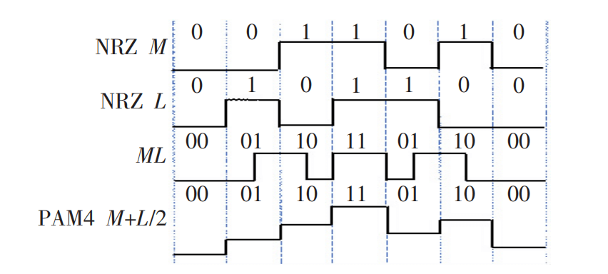
Figure 1. Schematic diagram of converting NRZ signal to PAM4 signal
ROSA converts the received optical signals into electrical signals and transmits them to the PAM4 codec chip, which in turn converts the PAM4 signals into two NRZ signals. The Microcontroller Unit (MCU) is involved in controlling the whole transmission process. Figure 2 shows the signal transmission block diagram of QSFP28 50Gbit/s optical module.
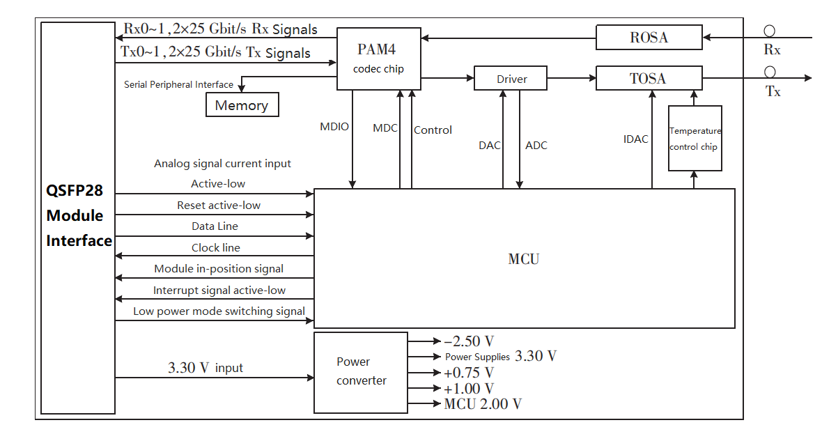
Figure 2. Signal transmission block diagram of QSFP28 50Gbit/s optical module
Design Principle Analysis of SFP56 50G Optical Module
Based on the QSFP28 50G optical module, there are three research directions for 50G optical modules in recent years.
(1) Use of smaller packages to avoid wastage of channels, facilitate laying as well as reduce power consumption.
(2) Improving the temperature applicability range of the module, such as upgrading the temperature applicability range from C-Temp (0 to 70 °C) to I-Temp (-40 to 85 °C).
(3) To enhance the optical transmission distance of the module, for example, to increase the optical transmission distance from 10 km to 40 km.
This study will start from these directions and design an SFP56 50G optical module with smaller package, higher performance, lower power consumption and longer transmission distance based on the technical background of QSFP28 50G optical module.
At the transmitter side, the PAM4 electrical signal is input to the SEMTECH GN2256 chip, which drives the External Modulated Laser (EML) to emit the 50G PAM4 optical signal after the Clock and Data Recovery (CDR) unit. Compared to the DML, the EML emits the same light and the laser driver drives the external modulator to adjust the actual light output size, which makes this type of laser more suitable for long-distance transmission. For the receiving side, the SFP56 and QSFP28 packages of optical modules work basically the same. The board frame of SFP56 50G optical module is shown in Figure 3.
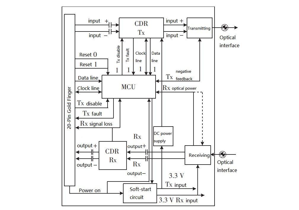
Figure 3. Board frame of SFP56 50G optical module
Comparison of 50G Optical Module Size and Power Consumption Between QSFP28 and SFP56
The size of the optical module will have a greater impact on the construction of the forwarding network. If the module can be made smaller for the same transmission rate, more modules can be installed on a single board of the same size. This increases the single board transmission rate and can also be considered as a smaller board size needed to achieve the same single board rate, which helps to reduce the device size.
Table 1 shows the size and cost of QSFP28 and SFP56 and power consumption at 50G transmission, as can be seen from the table, without taking into account the impact of the module length pull ring on the laying of the premise that.
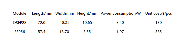
Table 1. Size and cost of QSFP28 and SFP56 and power consumption at 50G transmission
(1) The number of SFP56 packaged optical modules that can be laid on a single board of the same size is 1.68 times greater than the number of QSFP28 packaged optical modules that can be laid.
(2) The power consumption of a single SFP56 50G 40 km optical module is 57.9% of that of a QSFP28 50G 10 km optical module.
(3) The cost of a single SFP56 50G 40 km optical module is 213.88% of that of a QSFP28 50G 10 km optical module.
It can be concluded that laying SFP56 50G 40 km optical module on the same size single board compared with laying QSFP28 50G 10 km optical module, the power consumption is basically the same, but the single board rate is increased by 1.68 times, or achieving the same single board transmission rate, the single board area is reduced by 40.5% and the power consumption is reduced by 42.1%.
The cost of a conventional QSFP28 50G 10 km C-Temp (0 to 70 °C) optical module is about $180/pcs, and the cost of the SFP56 50G 40 km I-Temp (-40 to 85 °C) optical module in this design is about $385/pcs, so the cost of an SFP56 package optical module is only 26.6% of that of a QSFP28 package for the same distance and at the same transmission rate. The cost is only 26.6% of QSFP28 package.
Comparison Test of Optical Eye Pattern and Sensitivity of 50G QSFP28 and SFP56 Optical Module
Both QSFP28 50G 10 km C-Temp and SFP56 50G 40 km I-Temp optical modules can be tested either by self-loop or by adding an external light source. In order to avoid the influence of ambient temperature on the light source when measuring the parameters related to the ROSA side, this study chooses to build a test environment by adding an external light source for comparison testing. As shown in Figure 4, the light from the device under test (DUT) is divided by a beam splitter, and 90% of the light is fed into the Digital Communication Analyzer (DCA) to measure the parameters related to the optical eye diagram, and 10% of the light is fed into the Optical Spectrum Analyzer (OSA) to measure the wavelength and Side-Mode Suppression Ratio (SMSR). The light from the known optical module is fed into the DUT after passing through the Attenuator (ATT) to measure the DUT Rx related parameters, and the Bit Error Tester (BERT) provides the modulation signal for the Evaluation Board (EVB) and the clock signal for the DCA. The DUT is placed in a thermostat and the ambient temperature of its operation can be changed artificially, so that the optical module is known to be placed in a constant temperature environment. A multimeter is used for voltage calibration of the optical module, a Personal Computer (PC) is used to adjust the optical module parameters through a Graphical User Interface (GUI), and a power supply is used to power the two EVBs.
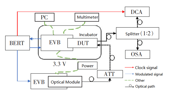
Figure 4. Test block diagram with added external light source
The optical eye diagrams of the two optical modules at room temperature are shown in Figure 5, and the related parameters are shown in Table 2. As can be seen from the table, the transmitter dispersion eye diagram closed quaternary (TDECQ) of QSFP28 50G optical module and SFP56 50G optical module at room temperature are 2.49 dB and 1.98 dB, respectively, with extinction ratios of 6.529 dB and 4.749 dB, and the average optical power was 1.73 dBm and 0.69 dBm, respectively.
The external light source is placed in room temperature environment and its operating state is kept constant. In the link, the light emitted from the external light source is input into the QSFP28 50G ROSA terminal and SFP56 50G ROSA terminal after ATT, and the sensitivity of these two modules at 25 °C is found to be -11.3 and -11.9 dB respectively after measurement.
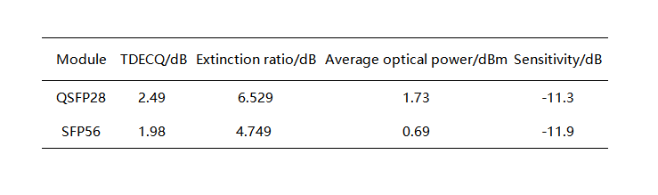
Table 2. Optical eye diagram related parameters of two optical modules at room temperature
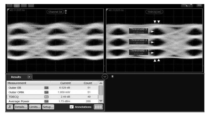
(a) QSFP28 50G
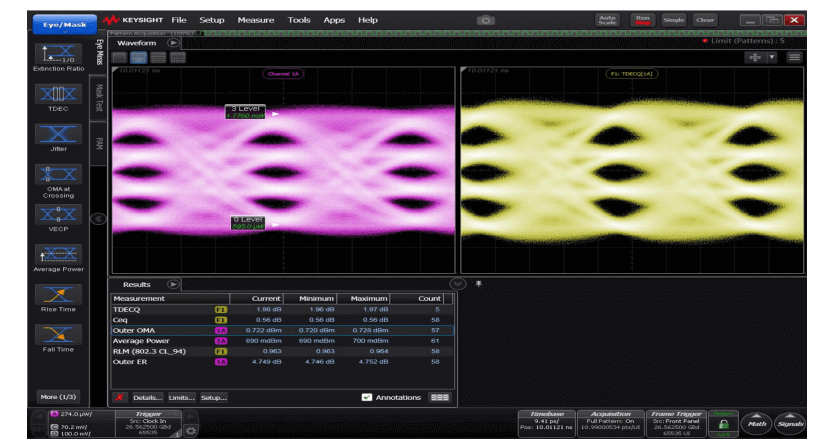
(b) SFP56 50G
Figure 5. Optical eye diagram at room temperature
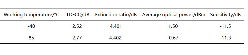
The optical eye diagram of SFP56 50G optical module at high and low temperature conditions is shown in Figure 6, and the related parameters are shown in Table 3. By adjusting the ambient temperature, the optical module is made to operate at -40 and +85 °C, respectively, and the light emitted from TOSA is fed into DCA after 40 km of fiber. After adjusting the relevant parameters, the TDECQ is 2.52 and 2.77 dB, the average optical power is 1.50 and 0.67 dBm, the extinction ratio is 4.401 and 4.402 dB, and the sensitivity is -11.5 and -11.3 dB, which are all in accordance with the Institute of Electrical and Electronics Engineers (IEEE) 802.3cd. Engineers (IEEE) 802.3cd 50G-related requirements.
Table 3. Optical eye diagram related parameters of SFP56 50G optical module under high and low temperature conditions
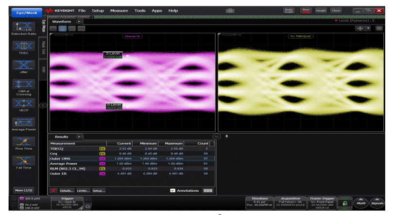
(a) -40°C
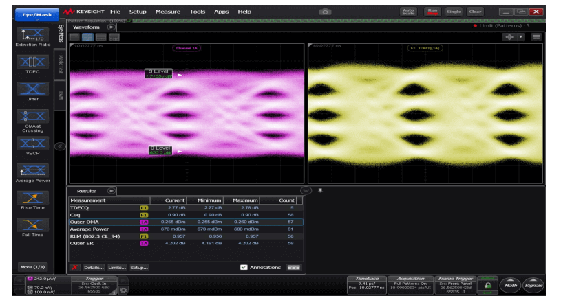
(b) +85°C
Figure 6. Optical eye diagram of SFP56 50Gbit/s optical module at high and low temperature conditions
Since the operating temperature range of the traditional QSFP28 50G optical module is 0 ~ +70 °C, while that of the SFP56 50G optical module in this study is -40 ~ +85 °C, it is not significant to compare the performance parameters of the two at 0 °C and +70 °C. The high and low temperature performance parameters of the module usually conform to the linear relationship, that is, the module with good performance at room temperature will also have good performance at high and low temperature. Therefore, it is only necessary to test the performance parameters of the SFP56 50G optical module when it works at -40 ℃ and +85 ℃. As long as the performance parameters of the module meet the relevant requirements of 50G in IEEE 802.3cd in this environment, the performance of the two optical modules with different packages can be determined by combining the performance parameters at room temperature.
As can be seen from Table 3, compared with QSFP28, the TDECQ is reduced by 20.5% and the sensitivity is increased by 0.6 dB after selecting SFP56. It can be concluded that the overall performance of the optical module is improved by about 20% after selecting SFP56 package, i.e. SFP56 package is more suitable for 50G optical module application than QSFP28 package.
Conclusion
This experiment proves that Fiber Mall has successfully designed a SFP56 50G 40 km I-Temp optical module based on the QSFP28 50G 10 km optical module with a smaller SFP56 package, replacing the PAM4 Gearbox codec chip with a SEMTECH GN2256 CDR chip, and combining TOSA, ROSA and EML. Compared with the traditional QSFP28 50G 10 km C-Temp optical module, the module cost is reduced by 73.4% and the overall performance of the module is improved by about 20%, which can work in more severe working environment and all indicators are in line with the 50G requirements of IEEE 802.3cd. SFP56 50G 40 km optical module. The SFP56 50G 40 km optical module has many advantages and can be expected to play a role in replacing the QSFP28 50G 10 km optical module in future 5G fronthaul networks.
Related Products:
-
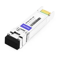
 SFP56-50G-LRI 50G SFP56 LR 1311nm PAM4 Duplex LC SMF 10km DDM Optical Transceiver Module
$390.00
SFP56-50G-LRI 50G SFP56 LR 1311nm PAM4 Duplex LC SMF 10km DDM Optical Transceiver Module
$390.00
-
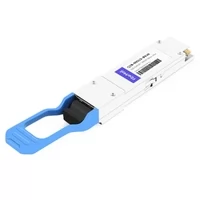
SFP56-50G-LRC 50G SFP56 LR 1311nm PAM4 Duplex LC SMF 10km DDM Optical Transceiver Module
$295.00
-
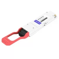
SFP56-50G-FRI 50G SFP56 FR 1311nm PAM4 Duplex LC SMF 2km DDM IND Optical Transceiver Module
$330.00
-
SFP56-50G-FRC 50G SFP56 FR 1311nm PAM4 Duplex LC SMF 2km DDM Optical Transceiver Module
$260.00
-
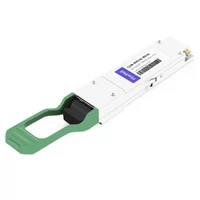
SFP56-50G-SR 50G SFP56 SR 850nm PAM4 Duplex LC MMF 100m Dual CDR DDM Optical Transceiver Module
$215.00
-
QSFP28-50G-ER 50G QSFP28 LR 1310nm 10km PAM4 LC SMF DDM Transceiver Module
$285.00
-
50G QSFP28 BIDI TX1309nm/RX1295nm PAM4 LC SMF 40km DDM Optical Transceiver Module
$450.00
-
50G QSFP28 BIDI TX1295nm/RX1309nm PAM4 LC SMF 40km DDM Optical Transceiver Module
$450.00
-
50G QSFP28 BIDI TX1331nm/RX1271nm PAM4 LC SMF 10km DDM Optical Transceiver Module
$230.00
-
50G QSFP28 BIDI TX1271nm/RX1331nm PAM4 LC SMF 10km DDM Optical Transceiver Module
$230.00
-
QSFP28-50G-ZR2 50G QSFP28 ZR2 1310nm (LAN WDM) 80km LC SMF DDM Transceiver Module
$2000.00
-
QSFP28-50G-LR 50G QSFP28 LR 1310nm 10km PAM4 LC SMF DDM Transceiver Module
$215.00