AIGC (AI-Generated Content) has been developing rapidly recently, and the iteration rate is exponentially exploding. Among them, the launch of GPT-4 and ERNIE Bot has drawn great attention to its business value and application scenarios. With the development of AIGC, the scale of training model parameters has gone from hundreds of billions to trillions of levels, and the scale of underlying GPU support has also reached trillion card levels. The resulting network scale keeps increasing, and the communication between network nodes faces increasing challenges. In this context, how to improve the AI server computing power and networking communication capability and take into account the cost has become one of the important research directions in the current AI field.
FiberMall launched the industry’s advanced “Smart Speed” DDC (Distributed Disaggregated Chassis) high-performance network solution to address the relationship between AIGC computing power, GPU utilization and network, as well as the challenges faced by mainstream HPC networking, to help AIGC business computing power soar.
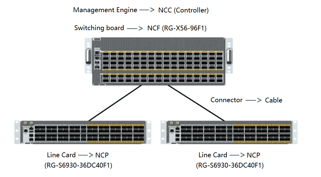
Diagram of FiberMall’s DDC product connection
Relationship Between AIGC Arithmetic Power, GPU Utilization and Network
Relationship Between Training Time and GPU Utilization of ChatGPT
Taking ChatGPT as an example, in terms of arithmetic power, the total arithmetic power consumption for training on Microsoft Azure AI supercomputing infrastructure (a high-bandwidth cluster of 10,000 V 100 GPUs) is about 3,640 PF-days (one thousand trillion calculations per second, running for 3,640 days), here is a formula to convert how long it takes to train 10,000 V 100s.
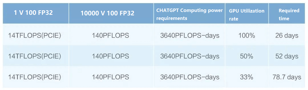
ChatGPT computing power and training schedule
Note: ChatGPT computing power requirements are available online and are provided here for reference only. In the article “AI and Compute”, OpenAI assumes a utilization rate of 33%, while a group of researchers at NVIDIA, Stanford and Microsoft have achieved utilization rates of 44% to 52% for training large language models on distributed systems.
It can be seen that the main factors affecting the training time of a model are the GPU utilization, and the GPU cluster processing power. These key metrics are in turn closely related to network efficiency. Network efficiency is an important factor that affects GPU utilization in AI clusters. In AI clusters, GPUs are usually the core resource of compute nodes because they can efficiently handle large-scale deep learning tasks. However, GPU utilization is influenced by several factors, among which network efficiency is a key factor.
Relationship Between Network Efficiency and GPU Utilization
The network plays a critical role in AI training, and AI clusters usually consist of multiple compute and storage nodes, which need to communicate and exchange data frequently. If the network is inefficient, the communication between these nodes will become slow, which will directly affect the computing power of the AI cluster.
Inefficient networks can lead to the following problems, which can reduce GPU utilization.
Increased data transfer time: In an inefficient network, the data transfer time will increase. GPU utilization will decrease when GPUs need to wait for data transfer to complete before they can perform calculations.
Network bandwidth bottleneck: In an AI cluster, GPUs usually need to exchange data with other compute nodes frequently. If the network bandwidth is insufficient, GPUs will not get enough data for computation, resulting in lower GPU utilization.
Unbalanced task scheduling: In an inefficient network, tasks may be assigned to different compute nodes from the GPUs. This may cause the GPU to wait idle when a large amount of data transfer is required, thus reducing GPU utilization.
In order to improve GPU utilization, network efficiency needs to be optimized. This can be achieved by using faster network techniques, optimizing the network topology, and rationalizing the bandwidth allocation. In the training model, the parallelism of distributed training: data parallelism, tensor parallelism and flow parallelism determines the communication model between the data processed by GPUs. The efficiency of communication between models is influenced by several factors:
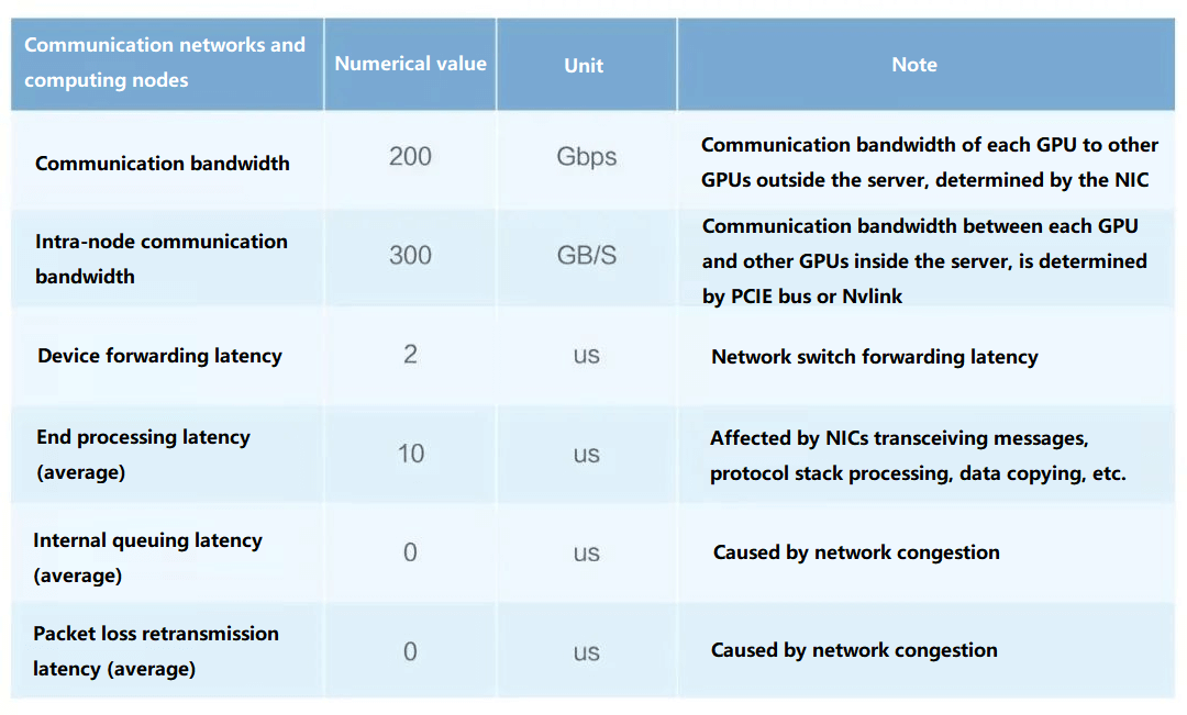
Factors affecting communication
Among them, bandwidth and device forwarding latency are limited by hardware, end-processing latency is influenced by the choice of technology (TCP or RDMA), RDMA will be lower, and queuing and retransmission are influenced by network optimization and technology choice.
Based on the quantitative model: GPU utilization = iterative computation time within GPU / (iterative computation time within GPU + overall network communication time) the following conclusions are drawn:
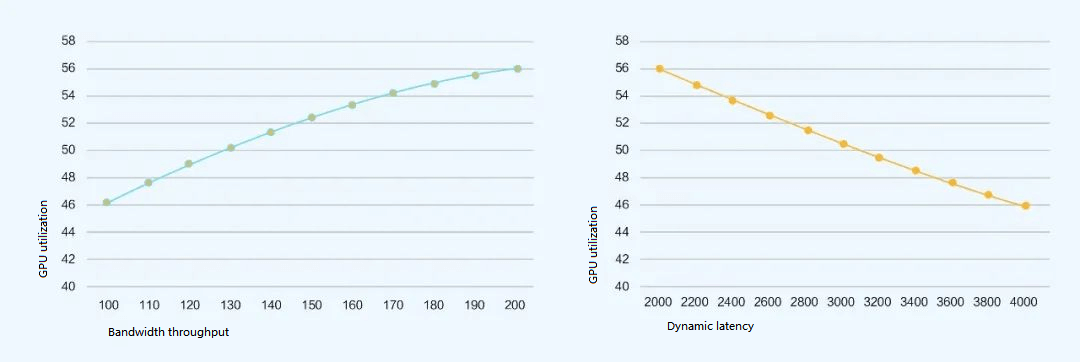
Graph of bandwidth throughput and GPU utilization Graph of dynamic latency and GPU utilization
It can be seen that network bandwidth throughput and dynamic latency (congestion/packet loss) have a significant impact on GPU utilization.
Based on the composition of the total communication latency:
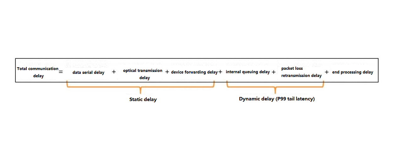
Composition of total communication latency
Static latency has a smaller impact, so it is more important to focus on how to reduce dynamic latency, which can effectively improve the utilization of GPU to achieve the goal of improving computing power.
The Challenges of Mainstream HPC Networking
IB Networking is Expensive and Closed
Infiniband networking is the most effective solution for current high-performance networks, using ultra-high bandwidth and Credit-based mechanisms to ensure no congestion and ultra-low latency, but it is also the most expensive solution. It is also the most expensive solution. It is several times more expensive than traditional Ethernet networking with the same bandwidth. At the same time, Infiniband technology is closed, and there is only one mature supplier in the industry, which makes it impossible for end users to achieve a second source of supply.
Therefore, most users in the industry will choose the traditional Ethernet networking solution.
PFC and ECN may Trigger a Speed Drop
The current mainstream networking solution for high-performance networks is based on RoCE v2 to build RDMA-enabled networks. Two important collocation technologies are PFC and ECN, both of which are created to avoid congestion in the link.
Under multi-stage PFC networking, it will target the switch ingress congestion and backpressure to the source server to suspend transmission step by step to relieve network congestion and avoid packet loss; however, this solution may face the risk of PFC Deadlock causing RDMA traffic to stop forwarding under multi-stage networking.
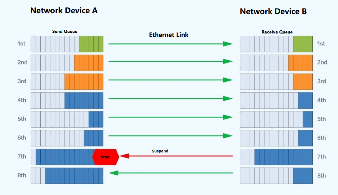
Schematic diagram of PFC working mechanism
While ECN generates a RoCEv2 CNP packet directly to notify the source of speed reduction based on destination-side awareness of congestion at the switch egress, the source server receives the CNP message and precisely reduces the sending rate of the corresponding QP to relieve congestion while avoiding indiscriminate speed reduction.
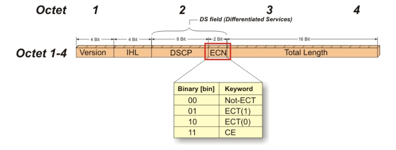
Schematic diagram of ECN
Both of these technologies are designed to solve congestion, but may be frequently triggered by possible congestion in the network. Eventually, the source end will pause or slow down the transmission speed, and the communication bandwidth will be reduced. The GPU utilization rate is greatly affected, which reduces the computing power of the entire high-performance network.
Unbalanced ECMP may Cause Congestion
In AI training calculation, there are two main models, All-Reduce and All-to-All, both of which require frequent communication from one GPU to multiple GPUs.
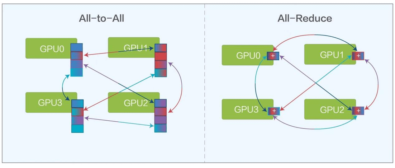
AI training calculation models
In traditional networking, ToR and Leaf devices adopt the routing +ECMP networking mode. ECMP performs hash load routing based on streams. In an extreme case, one ECMP link is full due to one elephant stream, while other ECMP links are relatively idle, resulting in uneven load.
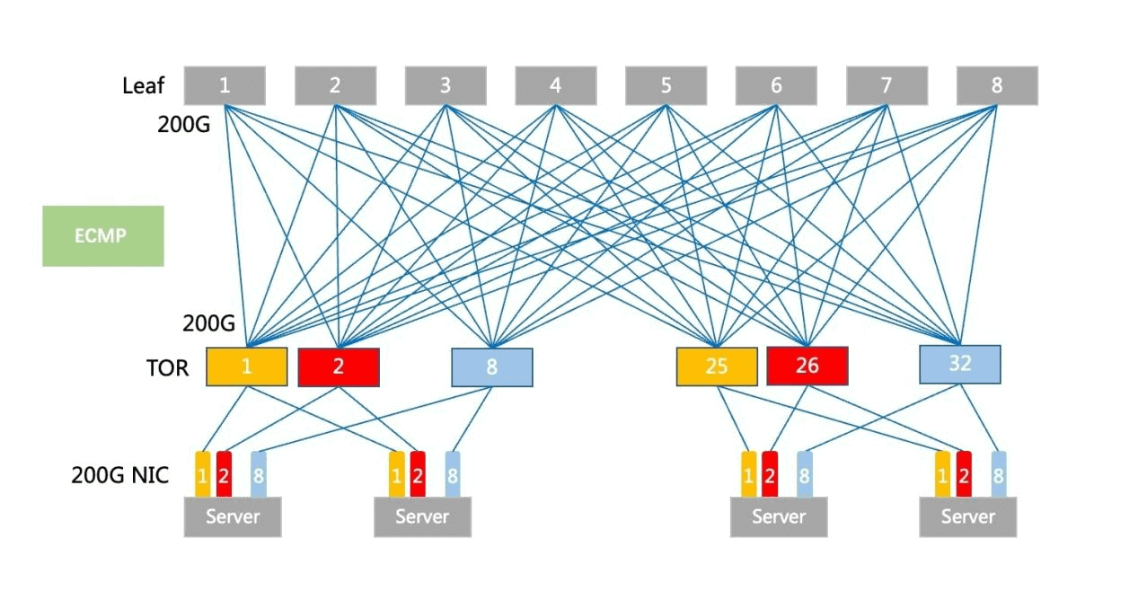
Traditional ECMP deployment diagram
In a test environment with 8 ECMP links simulated internally, the test results are as follows:
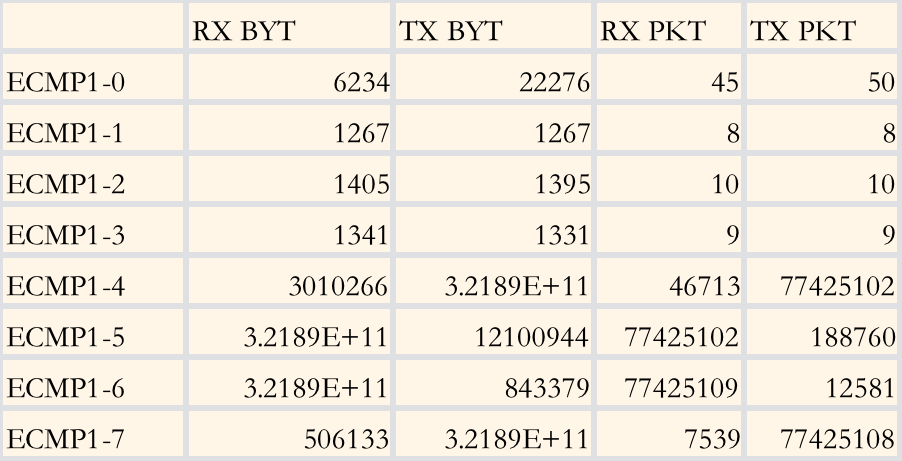
ECMP traffic test results
As can be seen, flow-based ECMP causes more obvious occupancy of certain links (ECMP1-5 and 1-6) and idleness (ECMP1-0 to 1-3 are idle). In both All-Reduce and All-to-All models, it is easy for a route to become congested due to uneven load on ECMP. Once the congestion causes retransmission, it increases the overall total communication latency and reduces GPU utilization.
Therefore, the research community has proposed rich solutions such as phost, Homa, NDP, 1RMA, and Aeolus. They address incast to varying degrees, and also address load balancing and low latency request/response traffic. But they also bring new challenges. Often, these studied solutions require end-to-end problem solving, with large changes to hosts, NICs, and networks, which is costly for the average user.
Challenges of AI Clustering with Box Switches
Some Internet companies look to box switches with DNX chips supporting VOQ technology to solve the problem of low bandwidth utilization due to load imbalance, but they also face several challenges as follows.
Average scalability. The frame size limits the maximum number of ports. If you want to do a larger scale cluster, you need to expand multiple frames horizontally, which also generates multi-level PFC and ECMP links. So the frame is only suitable for small-scale deployment.
Large power consumption of the device. The number of line card chips, Fabric chips, fans, etc. in the frame is large, and the power consumption of single device is great, easily more than 20,000 watts, some even more than 30,000 watts, with high power requirements for the cabinet.
The number of single device ports is large, and the failure domain is large.
So for the above reasons, box devices are only suitable for small-scale deployment of AI computing clusters.
DDC Products Born to Support AIGC
DDC is a distributed decoupled frame device solution, using almost the same chip and key technologies as traditional frame switches, but the DDC architecture is simple to support elastic expansion and rapid iteration of functions, easier to deploy, and low power consumption per machine.
As shown in the figure below, the service line card becomes the NCP role as the front end, and the switch board becomes the NCF role as the back end. The original connector components between the two are now replaced by fiber optic cables, and the management engine of the original frame device becomes the centralized/distributed management component of the NCC in the DDC architecture.
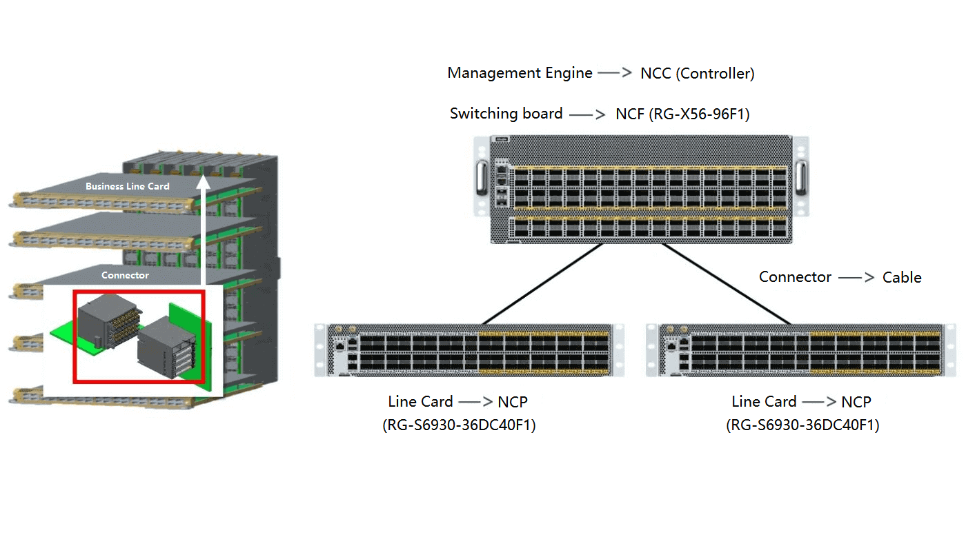
DDC product connectivity diagram
DDC supports ultra-large scale deployment
The advantage of DDC architecture over box architecture is that it can provide flexible scalability, and the network scale can be flexibly selected according to the size of AI cluster.
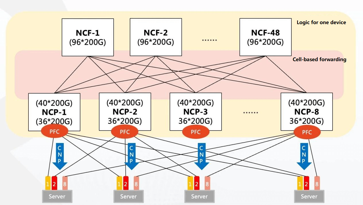
In the single POD network, 96 NCPs are used as accesses, of which 36 200G interfaces on the downlink of NCPs are responsible for connecting NICs of AI computing clusters. The upstream total of 40 200G interfaces can connect 40 NCFs, NCF provides 96 200G interfaces, and the upstream and downstream bandwidth of this scale is 1.1:1. The whole POD can support 3456 200G network interfaces, and according to the calculation of one server with 8 GPUs, 432 AI computing servers can be supported.
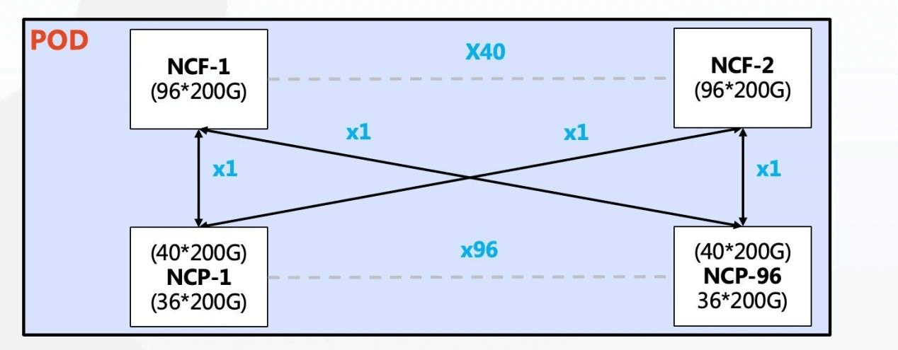
Single POD network architecture diagram
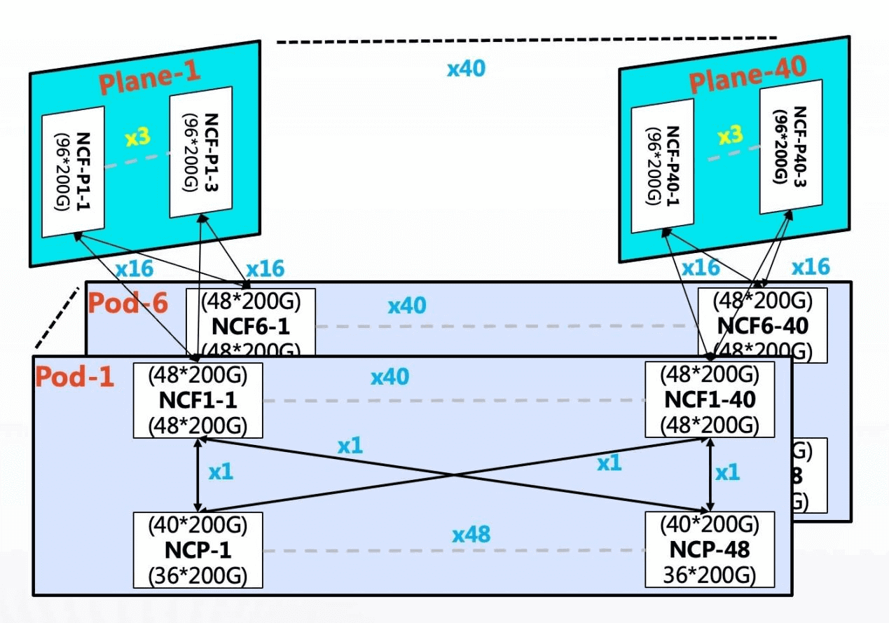
In multi-level POD networking, on-demand construction based on POD can be realized. Because the NCF equipment in this scenario POD has to sacrifice half of the SerDes for connecting the NCF of the second level, so at this time the single POD uses 48 NCPs as access, with a total of 36 200G interfaces in the downlink, and can support 1728 200G interfaces in a single POD. By increasing the POD horizontally to realize the scale expansion, the overall maximum can support more than 10,368 200G network ports.
NCP uplink 40 200G to 40 NCFs in POD, NCFs in POD use 48 200G interfaces downstream, and 48 200G interfaces are divided into 16 groups to uplink to NCFs in the second level. 40 planes are used for NCFs in the second level, and each plane is designed with 3 units, corresponding to 40 NCFs in POD.
The entire network achieves an overdrive ratio of 1:1:1 within the POD and a convergence ratio of 1:1 between the POD and the second-stage NCF.
The 200G network port is compatible with 100G NIC access, and in special cases, it is compatible with 25/50G NIC using 1 in 2 or 1 in 4 cables.
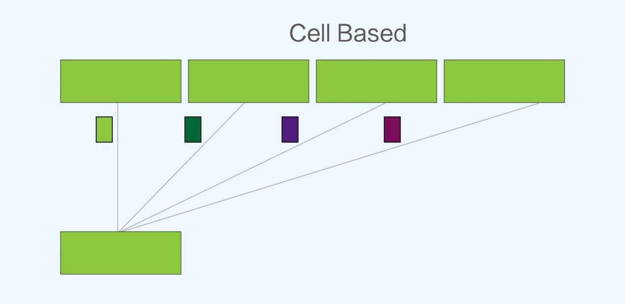
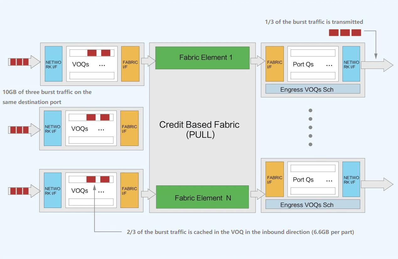
More balanced load based on VOQ+Cell mechanism, lower packet loss rate
Relying on the Cells forwarding mechanism after splitting for dynamic load balancing, it realizes the stability of delay and reduces the bandwidth peak difference of different links.
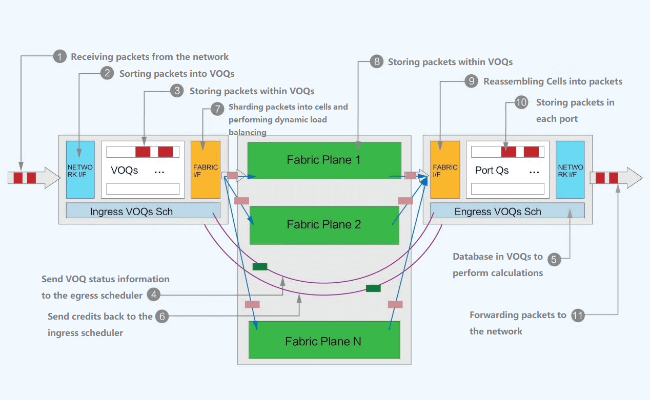
The forwarding process is shown in the figure:
First the sender receives packets from the network and sorts them into VOQs for storage. Before sending the packets a Credit message is sent to determine if the receiver has enough cache space to handle them.
If so, the packets are sliced into Cells and dynamically load balanced to intermediate Fabric nodes. These Cells are reassembled and stored at the receiving end and then forwarded to the network.
Cells are packet-based slicing techniques, typically 64-256 bytes in size.
The sliced Cells are forwarded according to the cell destination query in the reachability table and are sent using a polling mechanism. The advantage of this is that the load of sliced Cells will be fully utilized for each uplink and the amount of data transmitted on all uplinks will be approximately equal, compared to the ECMP mode of selecting a particular path after hashing by flow.
If the receiver is temporarily incapable of processing the message, the message will be temporarily stored in the VOQ on the sender side and will not be forwarded directly to the receiver side resulting in packet loss. Each DNX chip can provide an on-chip OCB cache and an off-chip 8GB HBM cache, which is equivalent to caching about 150ms of data for a 200G port. Credit messages are sent only when they are clearly acceptable at the other end. With such a mechanism, making full use of the cache can significantly reduce packet loss, or even not generate packet loss. With less data retransmission, the overall communication latency is more stable and lower, thus bandwidth utilization can be improved, and thus service throughput efficiency can be enhanced.
No Deadlock under PFC Single-hop Deployment
According to the logic of DDC, all NCPs and NCFs can be seen as one device. Therefore, after deploying RDMA domain in this network, there is only 1 level of PFC at the interface targeting the server, which will not generate multi-level PFC suppression and deadlock as in traditional networks. In addition, according to the data forwarding mechanism of DDC, ECN can be deployed at the interface, and once the internal Credit and cache mechanism cannot support the burst traffic, CNP messages can be sent to the server side to request speed reduction (usually under the communication model of AI, All-to-All and All-Reduce+Cell slicing can balance the traffic as much as possible, and it is difficult to have (1 port is filled up, so ECN can be unconfigured in most cases).
NCC-free design with distributed OS to enhance reliability
In the management and control plane, in order to solve the impact of management network failure and single point of failure of NCC, we eliminate the centralized control plane of NCC and build a distributed OS, configuring management devices through standard interfaces (Netconf, GRPC, etc.) by SDN operation and maintenance controllers, and each NCP and NCF is independently managed with independent control and management planes.
Test Comparison Results
From the theoretical point of view, DDC has many advantages such as supporting elastic expansion and rapid iteration of functions, easier deployment, and low power consumption of single machine; however, from the practical point of view, traditional networking also has advantages such as more brands and product lines available on the market, and can support larger scale clusters and other advantages brought by mature technology. Therefore, when customers are faced with project requirements, they can refer to the following comparison and test results to determine whether to choose a higher performance DDC or a traditional network for larger scale deployment:
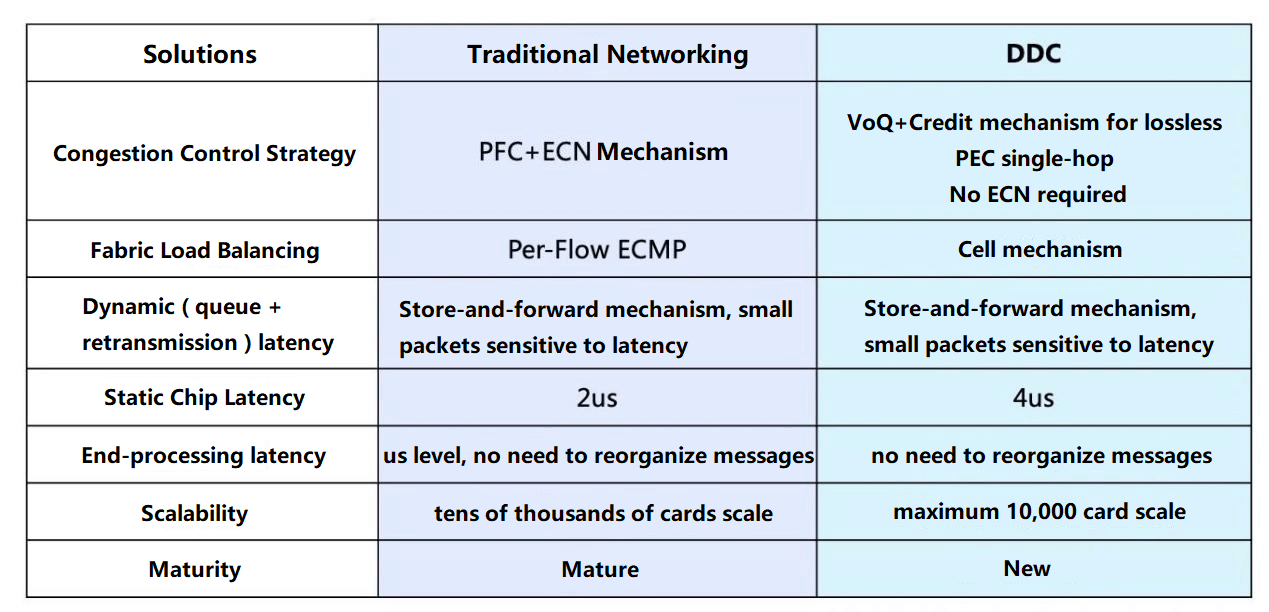
Comparison result between traditional networking and DDC test
FiberMall Equipment Introduction
Based on the deep understanding of customer needs, FiberMall has been the first to launch two deliverable products, 200G NCP switch and 200G NCF switch.
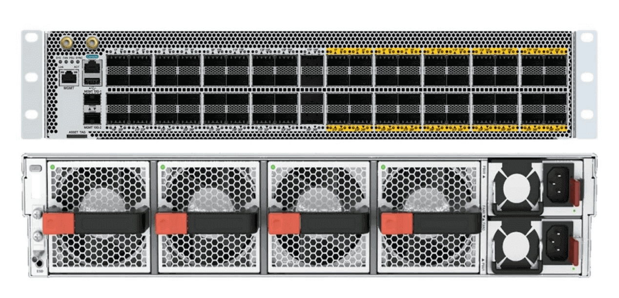
NCP: FM-S6930-36DC40F1 Switch
This switch is 2U high and provides 36 200G panel ports, 40 200G Fabric inline ports, 4 fans and 2 power supplies.
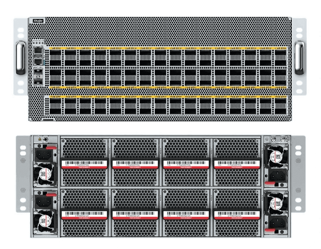
NCF: FM-X56-96F1 Switch
This switch is 4U high, providing 96 200G inline ports, 8 fans and 4 power supplies.
FiberMall will continue to develop and launch 400G port form factor products in the future.
Conclusion
FiberMall, as an industry leader, has been committed to providing high quality, high reliability network equipment and solutions to meet the increasing demand of customers for Smart Computing Center. While launching the “Smart Speed” DDC solution, FiberMall is also actively exploring and developing end-network optimization solutions in traditional networking. By making full use of server intelligent NICs and network equipment protocol optimization, the entire network bandwidth utilization can be improved to help customers usher in the AIGC smart computing era faster.
Related Products:
-
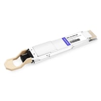
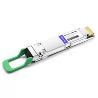
 QSFP-DD-200G-SR8 2x 100G QSFP-DD SR8 850nm 70m/100m OM3/OM4 MPO-16(APC) MMF Optical Transceiver Module
$350.00
QSFP-DD-200G-SR8 2x 100G QSFP-DD SR8 850nm 70m/100m OM3/OM4 MPO-16(APC) MMF Optical Transceiver Module
$350.00
-
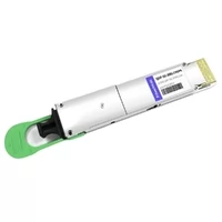
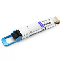
QSFP-DD-200G-CWDM4 2X100G QSFP-DD CWDM4 2km CS SMF Optical Transceiver Module
$1100.00
-
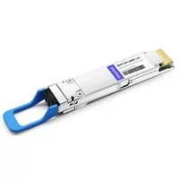
QSFP-DD-200G-LR4 200G QSFP-DD LR4 PAM4 LWDM4 10km LC SMF FEC Optical Transceiver Module
$1000.00
-
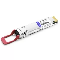
QSFP-DD-200G-ER4 200G QSFP-DD ER4 PAM4 LWDM4 40km LC SMF FEC Optical Transceiver Module
$1500.00
-
QSFP56-200G-SR4M 200G QSFP56 SR4 PAM4 850nm 100m MTP/MPO APC OM3 FEC Optical Transceiver Module
$139.00
-
QSFP56-200G-FR4S 200G QSFP56 FR4 PAM4 CWDM4 2km LC SMF FEC Optical Transceiver Module
$650.00
-
QSFP-DD-400G-SR8 400G QSFP-DD SR8 PAM4 850nm 100m MTP/MPO OM3 FEC Optical Transceiver Module
$149.00
-
QSFP-DD-400G-DR4 400G QSFP-DD DR4 PAM4 1310nm 500m MTP/MPO SMF FEC Optical Transceiver Module
$400.00
-
QSFP-DD-400G-FR4 400G QSFP-DD FR4 PAM4 CWDM4 2km LC SMF FEC Optical Transceiver Module
$500.00
-
QSFP-DD-400G-XDR4 400G QSFP-DD XDR4 PAM4 1310nm 2km MTP/MPO-12 SMF FEC Optical Transceiver Module
$580.00