The fronthaul network has an important impact on the transmission performance and quality of next-generation 5G and even 6G networks and is one of the hot spots in the research of new network and bearer technologies for mobile communications. Under the massive deployment of global C-RAN networking mode, 25G DWDM optical modules have been widely used in the current 5G forwarding network. For future higher channel Massive MIMO base stations, U6G band base stations, millimeter wave base stations, and other application scenarios, the bandwidth demand of the forwarding network will be further increased. On the premise of retaining the existing number of ports and saving fiber resources, FiberMall has initiated research on next-generation 5G forwarding optical module technology with 50Gb/s and higher speed. 50G SFP56
The 50G SFP56 optical transceiver module includes the 50G SFP56 dual-fiber bidirectional module and the 50G SFP56 single-fiber bidirectional (BiDi) module.
50G SFP56 Dual-Fiber Bidirectional Optical Transceivers
The functional block diagram and implementation mode of the 50G SFP56 dual-fiber bidirectional optical module is shown in Figure 1.
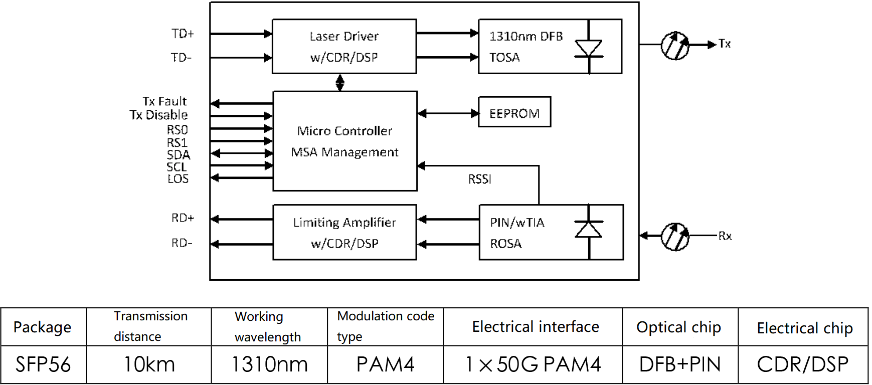
Figure 1. The functional block diagram and implementation mode of 50G SFP56 dual-fiber bidirectional optical module
The industry chain of 50G SFP56 dual-fiber bidirectional optical modules have taken shape. In terms of optical chips, the bandwidth requirement of DFB laser chip for 25Gb/s optical module with NRZ code type is about 17GHz. 50Gb/s optical module with PAM4 code type, the non-linear effect of laser is obviously enhanced, and it is necessary to further increase the bandwidth (about 19GHz) and optimize the inband spectrum ripple to reduce the non-linear effect.
There are several chip manufacturers available for volume supply, including foreign suppliers such as Lumentum, Sumitomo, Macom, Mitsubishi, etc. For electrical chips, there are two types of implementation solutions: DSP and CDR. The relevant vendors for DSP solutions include Marvell, Credo, and Sitrus Technology, all of which have released DSP chips for 5G fronthaul and integrated driver applications, and the relevant vendors for CDR solutions include Semtech and Macom. Among them, Semtech has already released CDR chips for 5G fronthaul and integrated drivers, and Macom’s CDR products with integrated drivers are in the development stage.
50G SFP56 dual-fiber bidirectional optical modules still face more problems and challenges in terms of performance, power consumption, and cost. First, in the core electrical chip solution selection, DSP solution can optimize the nonlinear problem in optical signal transmission by an internal algorithm. It has stronger processing power, better BER, and reception sensitivity performance, but at the cost of large signal transmission latency, higher power consumption, and cost, also needs to balance the impact of power consumption on the temperature of the optical module, keep the optical module temperature stability is an important requirement to ensure the stability and reliability of the front transmission link.
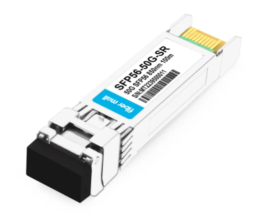
SFP56-50G-SR Module
The CDR solution has the advantages of high bandwidth, excellent transmitting performance, and low signal transmission latency. The power consumption and cost are lower, but the signal processing capability is weaker than DSP solution, and the response to MPI and link budget enhancement is yet to be verified. If DSP and CDR solutions coexist in the application, interconnection and interoperability are key technical issues that need to be addressed. Second, optical chip in the temperature control function of the use of industry is still divided. The temperature control function can make the laser in the whole module operating temperature range in a more ideal working condition. It can effectively control the laser wavelength and avoid the degradation of the laser bandwidth at the extreme temperature, but it will bring an increase of cost and power consumption. Without the temperature control function, the cost and power consumption of the module is relatively low and the process is simpler, but the requirements for the high-frequency performance of the optical chip are increased, and the application effect needs to be further verified. Finally, the complex deployment environment of the fronthaul network and the technical and engineering uncertainties of the fronthaul fiber link will place higher requirements on the 50G SFP56 optical module optoelectronic parameters.
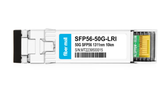
SFP56-50G-LRI Module
The international standard of 50G SFP56 dual-fiber bidirectional optical module for forward transmission has not yet been released, and optical module manufacturers are in the development or sample stage. The package is mainly SFP56, DDM, and interface definition reference SFF-8472, SFF-8431 protocol; electrical interface performance reference OIF-CEI-4.0 related provisions; optical interface performance in reference to IEEE802.3cd. On the basis of 50GBASE-LR, the wavelength range, transceiver power, sensitivity, and other indicators need to be amended according to the application scenario. The International Photonics & Electronics Committee (IPEC) has set up the next-generation mobile forwarding MFH50 standard project, focusing on 50Gb/s and higher speed fronthaul network requirements and networking solutions, optical interfaces, management interfaces, packaging and test methods, etc. The technical discussions on 50Gb/s dual-fiber 10km distance specifications are currently underway.
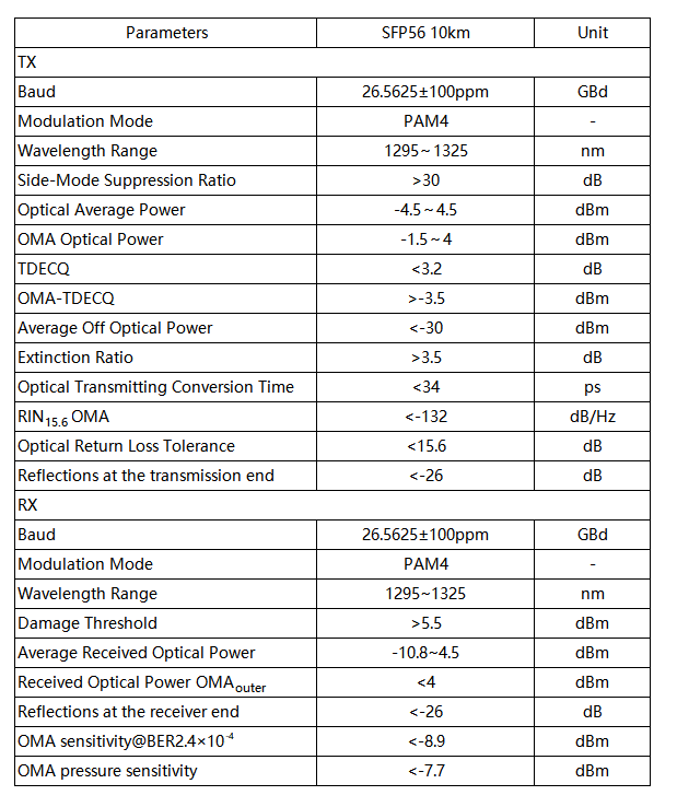
Table 1. 50G SFP56 dual-fiber bidirectional optical module key parameters index
By the end of 2022, FiberMall can provide samples of 50G SFP56 dual-fiber bidirectional optical modules (CDR or DSP solutions) for fronthaul. Nokia and other system equipment vendors have conducted testing and validation, and the high and low-temperature test results basically meet the requirements of IEEE 802.3cd and IPEC MFH50 draft standards, and in the second half of 2022, multi-vendor, multi-solution interconnection testing, and validation. FiberMall’s 50G SFP56 dual-fiber bidirectional optical modules for fronthaul is expected to be ready for mass production in the first half of 2023.
50G SFP56 BiDi Optical Transceivers
The functional block diagram and implementation of the 50G SFP56 BiDi optical module are shown in Figure 2.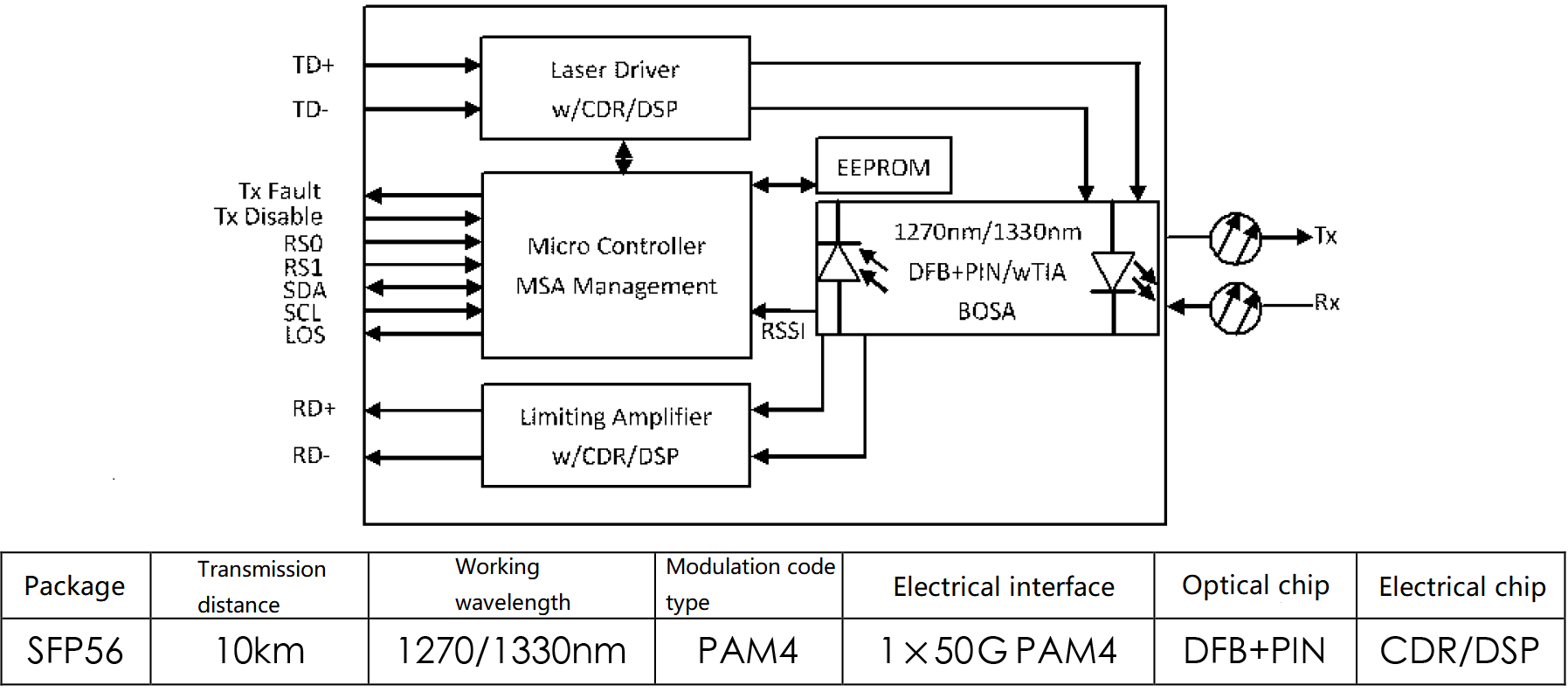
Figure 2. 50G SFP56 BiDi optical module functional block diagram and implementation method
The 50G SFP56 BiDi optical module still adopts the 1270nm/1330nm WDM scheme of the 25Gb/s BiDi optical module, which has the advantages of saving fiber resources and good delay symmetry compared with the dual-fiber bidirectional optical module and can share the 50G SFP56 dual-fiber bidirectional optical module industry chain.
At present, the industry optical module manufacturers of 50G SFP56 BiDi optical module product development are based on 50Gb / s dual-fiber optical module solution, development progress is slightly later than the 50G SFP56 dual-fiber optical module, the current overall in the pre-research or development stage. The domestic and international standards for 50G SFP56 BiDi optical modules for fronthaul have not yet been released, and the status of research on key parameters in the design of some modules is shown in Table 2.
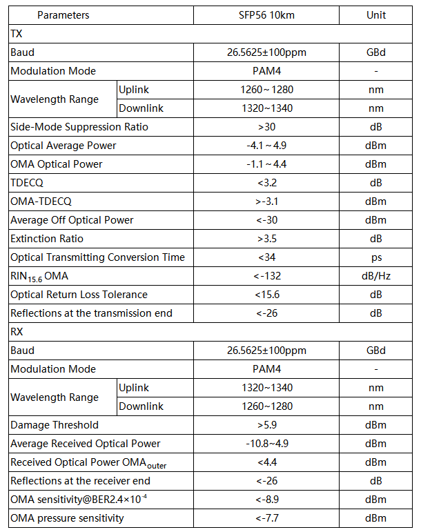 Table 2. Research status of key parameters of 50G SFP56 BiDi optical transceiver module
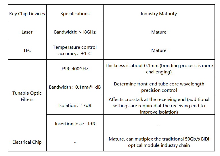
Table 3. 50Gb/s wavelength self-tuning BiDi module chip device industry chain
The 50G SFP56 BiDi optical module for 5G fronthaul can multiplex the 25Gb/s BiDi optical module BOSA scheme and 50Gb/s dual-fiber bidirectional optical module industry chain, and FiberMall is expected to have mass production capability in the first half of 2023.
50G SFP56 CWDM Optical Transceivers
Based on the research of 25G CWDM SFP28 optical module, FiberMall started to explore the technical solutions of xWDM module with higher speed, among which, the research of 50Gb/s 6-wavelength CWDM optical module is progressing faster.
50G CWDM SFP56 has 6 wavelengths: 1271nm,1291nm,1311nm,1331nm,1351nm, and 1371nm, which is consistent with the 6 wavelength optical module of 25G CWDM SFP28. In terms of optical chip, 50G SFP56 CWDM optical module can be multiplexed with 25GBaud CWDM laser chain, but considering the introduction of PAM4 modulation code type, the demand for link budget increases and higher requirements for laser output power is required to further optimize the laser luminous efficiency and yield.
In terms of electrical chips, 50G CWDM SFP56 optical modules are similar to 50G SFP56 dual-fiber optical modules, and there are two implementation solutions, CDR and DSP. CWDM optical modules have a wide wavelength span and different dispersion costs for different wavelengths, and the industry is exploring the possibility of two solutions co-existing to achieve the best cost performance. For example, the CDR solution is adopted for the 1311nm wavelength with a lower dispersion cost, and the DSP solution is adopted for the 1371nm wavelength with a higher dispersion cost. In the industry chain, the use of CDR or DSP single-channel approach with integrated driver can simplify hardware design and reduce power consumption. Electric chip maker, Semtech has mass production CDR integrated driver, as well as TIA’s set of chip solutions.
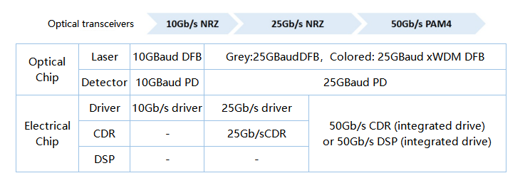
Table 4. xWDM optical module optoelectronic chip evolution schematic
At present, 50G CWDM SFP56 optical modules still have dispersion penalty, MPI, power consumption and heat dissipation, CDR and DSP interoperability and other technical issues to be solved.
- Dispersion penalty: The source of dispersion in the 5G fronthaul link is mainly material dispersion and waveguide dispersion, and is dominated by material dispersion. The zero dispersion point of G.652 fiber is near 1310nm wavelength, and the amount of dispersion in the typical application scenario (10km) of fronthaul is shown in Table 5. The CWDM6 wavelengths dispersion risk is the largest wavelength of 1371nm, and the dispersion amount of 10km is 36~66.2ps/nm.
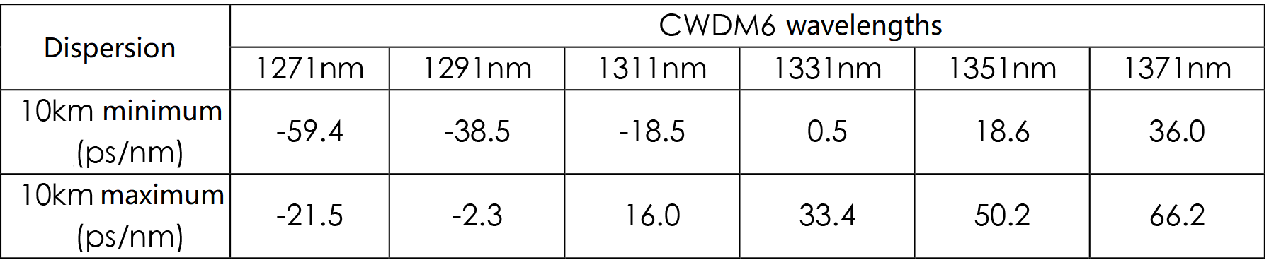
Table 5. Dispersion of typical 5G fronthaul scenarios (10km)
The mainstream dispersion penalty solutions in the industry are shown in Table 6. Among them, the dispersion fiber/grating scheme requires dispersion measurement of the front transmission link in advance, and the length and other parameters of the dispersion fiber/grating are customized according to the site and placed externally in the optical module, which is more difficult to implement; the DSP compensation scheme can compensate dispersion in the electric domain, but the compensation capability of each manufacturer is inconsistent, and the specific compensation capability needs to be obtained through actual measurement; the 50Gb/s CWDM optical module generally adopts DML If external modulation scheme (EML/MZM) is adopted, the laser chirp effect can be reduced, thus reducing the dispersion cost; the micro-loop dispersion compensation scheme can compensate up to 720ps/nm and is currently in the research stage.
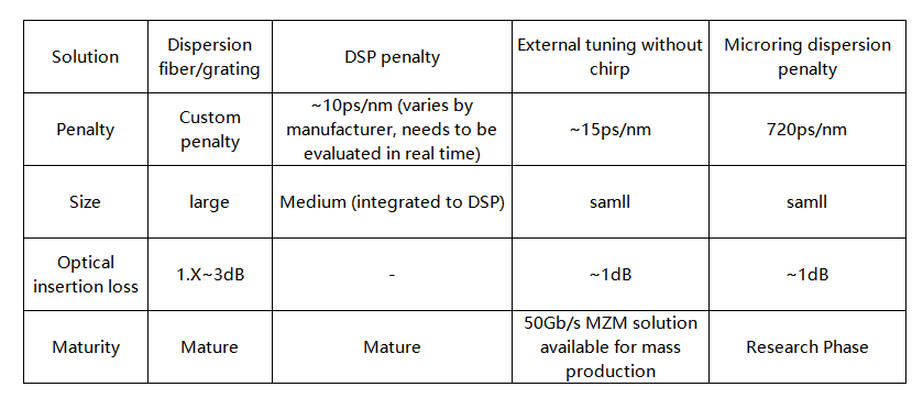
Table 6. The mainstream dispersion penalty solutions
Through actual testing, the high-temperature dispersion cost of 50G CWDM SFP56 optical module at 1371nm wavelength is about 3dB, which is constrained by 50G CWDM SFP56 optical module link budget constraints, the margin is not enough, DSP compensation scheme may be more advantageous.
MPI challenge: In optical fiber links, reflected interference signals unrelated to the original signal will be generated due to small refractive index changes of the optical fiber system, discrete reflection caused by dirty or poor contact of the end face of the connector, and Rayleigh backscattering. Mixing the interference signals with the original signal will generate noise, resulting in the deterioration of the signal-to-noise ratio and reducing the transmission performance of the system. The ratio of the sum of all reflected signal power to the original signal power was defined as multipath interference (MPI). The intensity of MPI mainly depended on the reflectance of the connector and the number of reflected points. The larger the reflectance, the more reflected points, and the worse the MPI. According to the IEEE802.3 Ethernet standard, it is recommended to convert the MPI cost into Link Loss based on the simulation of the universal link model, and improve the tolerance through FEC.
In a 5G fronthaul network, taking a typical C-RAN scenario as an example, there are generally 6 connectors (ODF shelf on both sides and co-divider on both sides). If we refer to the Ethernet standard, we need to constrain the return loss of each connector <-35dB, but some of the fronthaul links have degraded connector return loss of about -26dB, and there is a certain risk of MPI in the fronthaul links. The system equipment vendor HW and Shanghai Jiaotong University jointly constructed a fronthaul simulation model, and the MPI cost simulation results are shown in Table 7. The simulation model (number of connectors, typical values of connector reflectivity, connector location, etc.) will be further corrected according to the research of typical scenarios in the existing network subsequently.
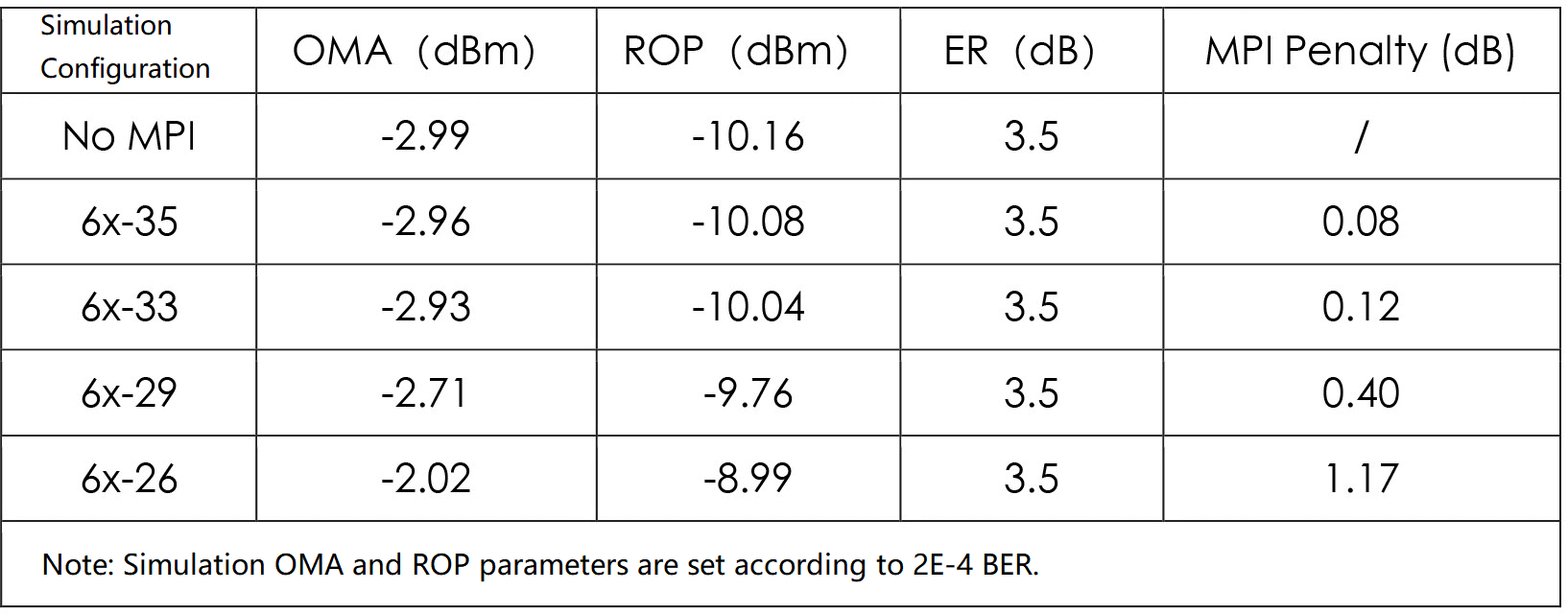
Table 7. MPI simulation results
Power consumption: 5G fronthaul scenarios need to consider industrial grade temperature (-40°C~+85°C) or extended commercial grade temperature (-20°C~+85°C) application requirements. Under the ambient temperature constraint, the power consumption of 50G SFP56 optical module and 50G SFP56 CWDM module is expected to be no more than 2W. The industry has tested the power consumption of 50Gb/s gray optical module based on CDR and DSP solution, and 50Gb/s CWDM color optical module based on DSP solution. The power consumption of the 1371nm optical module is more than 2W, and the DSP chip needs to be further optimized to reduce power consumption.
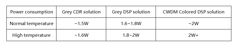
Table 8. Power consumption of the 50G optical module
In summary, 50G CWDM SFP56 transceivers need to be fully considered for power budget allocation in application scenarios with transmission distances of 10km and above. 50Gb/s PAM4 signals require increased receive sensitivity compared to 25Gb/s NRZ signals, requiring a weighing between transmit optical power, receive sensitivity, and dispersion penalty.
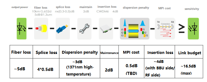
Figure 2. 50G CWDM SFP56 optical module link budget
By the end of 2022, FiberMall has provided samples of 50G CWDM optical modules in multiple scenarios. Based on this, the system equipment vendor has carried out basic functions, transceiver performance, and dispersion cost tests in the full temperature range, as well as multi-vendor and multi-program interconnection tests, with relatively good verification results.
Further testing is planned for the optimized products in 2023, and the test results will be used as a reference for the IPEC MFH standard development. The 50G CWDM SFP56 optical module is expected to mature in the second half of 2023.
Research on Management Interface of 50G SFP56 Transceiver
With the introduction of new rates, the selection and definition of management interfaces for next-generation 5G fronthaul optical modules need to be based on the potential new problems and new requirements to be supported by optical modules, taking 50G SFP56 optical modules as an example, the following issues and requirements are being discussed in the industry.
Support for rate set reporting function
The fronthual optical module needs to support different rates. For example, 25G SFP28 optical modules need to support 25.7Gb/s and 10.3Gb/s for eCPRI protocol, and 24.3Gb/s, 10.1Gb/s, and 9.8Gb/s for CPRI protocol, so the master equipment requires optical modules to have the function of reporting rate set so that the optical modules can be reasonably configured according to the reported rate set.
The SFF-8472 protocol stack provides an Application Select Table function, where each application can be assigned a unique “application code” containing information such as protocol name, operating rate, modulation code type (NRZ or PAM4), etc. The 50G SFP56 optical The 50G SFP56 module can integrate this Application Select Table function and report its supported rate set as shown in Table 9.
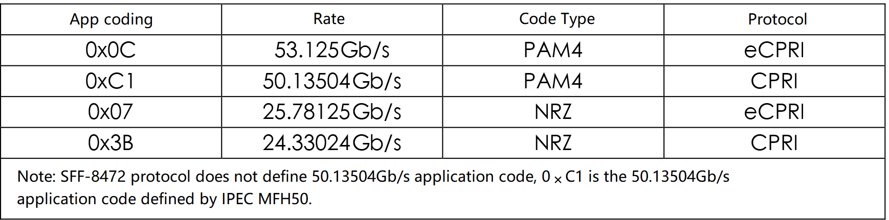
Table 9. Application codes that be supported by the 50G SFP56 optical module
Precise delivery rate during switching
Both 25G SFP28 and 10G SFP+ optical modules adopt NRZ modulation codes. When switching rates, and only need to switch the electrical interface SerDes rate or optical interface operating rate. The optical module can be locked in a short time and work at the new rate. The 50G SFP56 transceiver introduces PAM4 modulated codes and new CDR or DSP technology. Both electrical and optical signals have three decision levels, which are acquired through “training and learning”. he CDR or DSP chip needs to obtain the exact operating rate and code type when switching rates in order to achieve “training and learning” more quickly. Combined with the rate set reporting function of the optical module mentioned earlier, the master device delivers the exact working rate and code type by delivering the Application code to the optical module when switching rates.
Reporting switchover setup time
When rate switching, after the master device sends the rate switching command to the optical module. To “optical module input signal to meet the protocol requirements of the signal quality” for the beginning, to “optical module channel lock and output the corresponding signal” for the end, this time is called the switch setup time. It is also divided into optical-electrical conversion channel (Egress) setup time and electrical-optical conversion channel (Ingress) setup time.
10G SFP+ and 25G SFP28 optical modules are based on NRZ code type, only need to “train or learn” a threshold value, the rate switch setup time is short (generally within 1ms order of magnitude), switching reliability is high, the main equipment generally ignores the time. When the target rate and code type is 50Gb/s PAM4, CDR or DSP needs to “train or learn” 3 threshold values, the switching setup time can be seconds or even more than 10 seconds, and there is a possibility of unsuccessful switching, so the optical module must take the initiative to report Therefore, the optical module must actively report the “maximum switching setup time” and “switching success flag”.
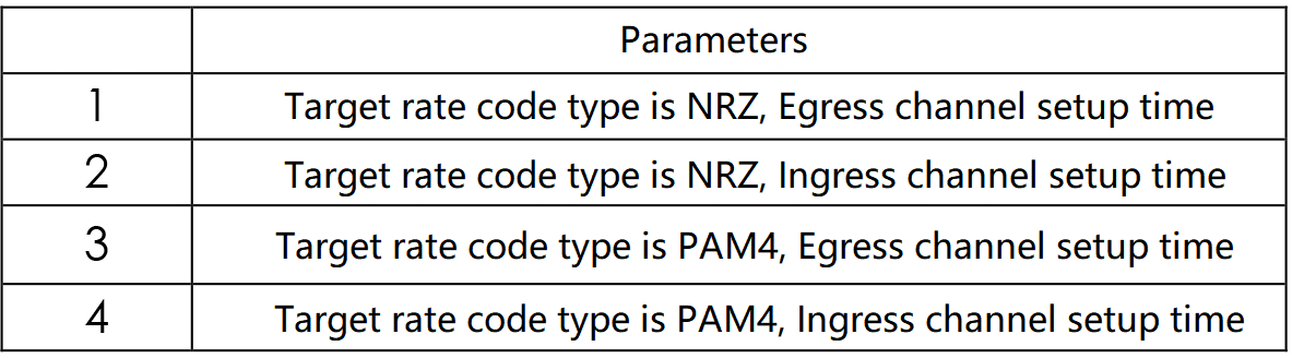
Table 10. Setup time register template
The “Switching success sign” can help the master device to obtain the switching status of the optical module. It is necessary to distinguish between the “Egress channel” and “Ingress channel” signs. When the master device queries that the optical module has been successfully switched, it can negotiate the protocol layer such as CPRI or eCPRI.
Reported transmission latency
The transmission latency introduced by the optical module in the photoelectric conversion is related to the electrical chip solution, modulation code type, and PCB alignment of the optical module. 10G SFP+ and 25G SFP28 optical modules usually have a transmission latency in the order of hundreds of ps, which has a small impact on the fronthaul link; however, the transmission latency introduced by the 50G SFP56 optical transceiver based on the DSP solution reaches tens of ns, which has an impact on the fronthaul synchronous transmission system. There is the possibility of affecting the forward synchronous transmission system, so the optical module shall define the register in the management interface to declare the transmission delay introduced by the optical module to facilitate the analysis and judgment of the main equipment.
Report the support of new features
Compared with the CDR solution, the 50G SFP56 optical module based on the DSP solution can provide new functions such as loopback, signal-to-noise ratio detection, BER detection, etc. It can be stated in the optical module management interface which new features and functions it supports, while the management interface can provide registers to obtain the detection results.
In summary, in order to solve and meet the above problems and demands, new management interfaces are needed for next-generation 5G fronthaul optical modules. Currently, the mainstream management interface protocols in the industry include SFF-8472 and OIF CMIS, etc.
Table 11 shows a partial comparison of SFF-8472 and CMIS protocols. CMIS protocol is the standard protocol for QSFP-DD optical modules, which is applicable to multi-channel and can be used for single-channel fronthaul optical modules after tailoring. Because the CMIS protocol stack is new, the above new features are defined in the protocol stack, which is more comprehensive in terms of functional breakdown. The SFF-8472 protocol is widely used in 10Gb/s and 25Gb/s optical modules, with the advantage, that a large amount of code from the master device can be The SFF-8472 protocol is widely used in 10Gb/s and 25Gb/s optical modules. The SFF-8472 protocol is widely used in 10Gb/s and 25Gb/s optical modules.
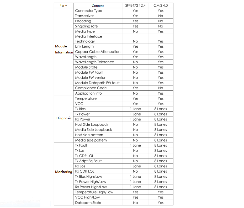
Table 11. Comparison of SFF-8472 and CMIS
50G Wavelength Tunable BiDi SFP56 Transceiver
IEEE802.3cp and CCSA have issued international and industry standards respectively, and the recommended wavelengths for upstream and downstream are shown in Table 12. The traditional 50G BiDi SFP56 optical module has to be paired due to the inconsistent wavelengths at both ends, which makes it more challenging for material resources and maintenance management due to potential AB-end misinsertion and pairing abnormalities in the actual use.
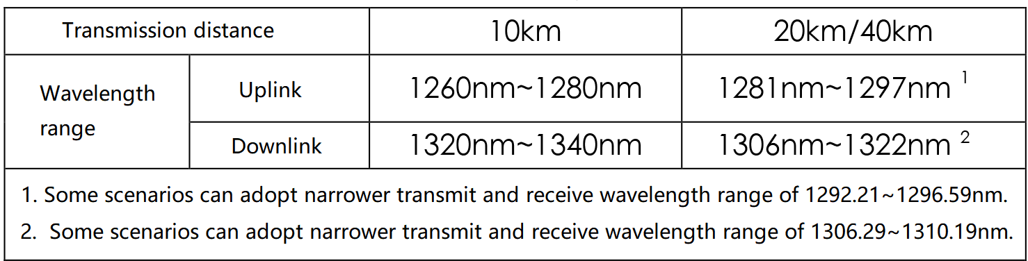
Table 12. 50G BiDi optical module wavelength recommendations
FiberMall proposes a new solution for 50G wavelength Tunable BiDi SFP56 optical modules, which can break the “upstream and downstream” wavelength constraint of traditional BiDi optical modules. The schematic diagram is shown in Figure 3.
The electrical interface solution is the same as the traditional 50Gb/s BiDi optical module, supporting 2x25Gb/s NRZ and 1x50Gb/s PAM4 types. The core electrical chips such as DSP, Driver, and TIA are also the same as the traditional 50Gb/s BiDi optical module. The optical path of the module contains a laser and an optical filter. The output wavelength of the laser needs to match the passband/stopband wavelength of the filter, so the laser needs to use a wavelength-tunable laser or realize the adjustment of the laser wavelength change through TEC temperature control. At the same time, wavelength monitoring can be performed by tunable optical filter and monitoring loop, and the whole system is adaptively matched by software handshake to realize the data signal transmission at both ends of the optical module.
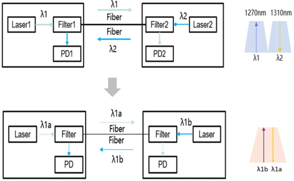
Figure 3. Schematic diagram of wavelength self-tuning BiDi optical module
Wavelength tunable technology for lasers and optical filters is the main difficulty and challenge of this solution. In terms of lasers, the optimal cost solution is to achieve laser wavelength tunability through TEC temperature control, but the disadvantage is the limited wavelength tuning range.
TEC temperature control is generally within the range of 10~20℃, the laser wavelength tunable range is limited to ±1nm, and the emission wavelength channel interval of the optical module needs to be set to about 1nm.
The DFB or FP lasers cannot meet the requirements due to the large spectral width, so EML lasers with a typical spectral width of less than 0.2 nm are required.
In addition, from the perspective of dispersion tolerance, the single-fiber unidirectional optical module has a narrower wavelength range, which is conducive to longer-distance transmission and WDM expansion. In terms of optical filters, thermal tuning is also preferred to achieve wavelength tunability, but special attention should be paid to thermal crosstalk and other issues in the design.
In terms of technical specifications, the link budget of 50G wavelength Tunable BiDi SFP56 transceiver can be consistent with the traditional 50Gb/s optical module. The power consumption is less than 3.5W under 0~70℃ full temperature conditions, the wavelength is freely switchable between 1308nm/1309nm, and the typical time for wavelength switching stability and service establishment at both ends is less than 10s. At the end of 2021, CCSA discussed the line standard project plan for this technology solution, and the preliminary estimate is that the industry standard will be released in the second half of 2023.
In terms of the industry chain, the 50G wavelength Tunable BiDi SFP56 optical module has a new wavelength tunable laser, wavelength tunable optical filter, and software adaptive matching compared with the traditional 50Gb/s BiDi optical module. As analyzed above, laser wavelength tunable can be achieved by TEC temperature control, software adaptive matching can be achieved by a combination of optical wavelength monitoring and built-in software functions, and wavelength tunable optical filter is a new addition to the industry chain.
Currently, the industry solutions for wavelength tunable filters are Etalon + temperature control, adjustable PLC, etc. The key technical parameters include FSR, bandwidth, isolation, etc. The key indicators of the device in the optical module (wavelength adjustment range, sensitivity, isolation, etc.) can be decomposed downward to get the specifications of the device and process to achieve technical analysis, the maturity of the industry chain needs to be further enhanced.
Related Products:
-
 SFP56-50G-LRI 50G SFP56 LR 1311nm PAM4 Duplex LC SMF 10km DDM Optical Transceiver Module
$390.00
SFP56-50G-LRI 50G SFP56 LR 1311nm PAM4 Duplex LC SMF 10km DDM Optical Transceiver Module
$390.00
-
SFP56-50G-LRC 50G SFP56 LR 1311nm PAM4 Duplex LC SMF 10km DDM Optical Transceiver Module
$295.00
-
SFP56-50G-FRI 50G SFP56 FR 1311nm PAM4 Duplex LC SMF 2km DDM IND Optical Transceiver Module
$330.00
-
SFP56-50G-FRC 50G SFP56 FR 1311nm PAM4 Duplex LC SMF 2km DDM Optical Transceiver Module
$260.00
-
SFP56-50G-SR 50G SFP56 SR 850nm PAM4 Duplex LC MMF 100m Dual CDR DDM Optical Transceiver Module
$215.00