
1. Introduction of semi-active MWDM system
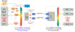
The semi-active MWDM system needs to support the end-to-end management and control of the fronthaul network, including the end-to-end monitoring and management of the fronthaul MWDM equipment, optical modules, and optical paths. The optical module supports the monitoring of the fronthaul optical path and supports the receiving and sending of management and control information. The active equipment of the system supports the management and control of the fronthaul network.
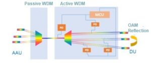
OAM technology uses pilot tone signals to transmit management and control information in the optical layer. The optical modules at both ends perform information modulation on the pilot tone signal according to the management and control information and send it to the opposite end through passive and active WDM equipment.
As shown in the system diagram:
2. Requirements of MWDM optical module
The MWDM system optical module supports obtaining the management and control information of the semi-active MWDM fronthaul system and transmits the information. The optical module supports inserting and extracting the management and control of OAM information from the optical signal and sends the signal to the opposite end.
- Performance specifications:
| Parameters | Specifications | Unit |
|---|---|---|
| Operating Wavelength | 1260~1620 | nm |
| Channel | 1267.5,1274.5,1287.5,1294.5,1307.5,1314.5,1327.5,1334.5,1347.5,1354.5,1367.5,1374.5 | nm |
| Center wavelength deviation | ±1.2 | nm |
| 1dB passband width | ≥5 | nm |
| Passband flatness | ≤0.5 | dB |
| Channel Passband(@-0.5dB bandwidth) | ±2.5 | nm |
| Insertion Loss | See attached table for details | dB |
| Insertion loss uniformity | dB | |
| Adjacent Channel Isolation | >30 | dB |
| Non-adjacent Channel Isolation | >35 | dB |
| Insertion Loss Temperature Sensitivity | <0.5 | dB |
| Wavelength Thermal Stability | <0.002 | nm/℃ |
| Insertion Loss Thermal Stability | <0.007 | dB/℃ |
| Polarization Dependent Loss | <0.15 | dB |
| Polarization Mode Dispersion | <0.1 | ps |
| Directivity | >50 | dB |
| Return Loss | >40 | dB |
| Maximum Power Handing | 300 | mW |
| Optical power detection accuracy | ±1.5 | dB |
| OLP protection switching time | <50 | ms |
| Single card power consumption | ≤4 | W |
| Operating Temperature | -10~+70 | ℃ |
| Storage Temperature | -40~+85 | ℃ |
| Fiber Type | G657A1 | |
| Connector | LC/UPC | |
| Package size | 177×190×20 | mm |
- Insertion Loss Specifications :
| Parameters | Wavelength | Specifications | Unit |
|---|---|---|---|
| Insertion Loss | 1267.5nm | ≤ 2 | dB |
| 1274.5nm | ≤ 2.2 | dB | |
| 1287.5nm | ≤ 2.4 | dB | |
| 1294.5nm | ≤ 2.6 | dB | |
| 1307.5nm | ≤ 2.8 | dB | |
| 1314.5nm | ≤ 3 | dB | |
| Insertion Loss | 1327.5nm | ≤ 1.8 | dB |
| 1334.5nm | ≤ 2 | dB | |
| 1347.5nm | ≤ 2.2 | dB | |
| 1354.5nm | ≤ 2.4 | dB | |
| 1367.5nm | ≤ 2.6 | dB | |
| 1374.5nm | ≤ 2.8 | dB |
*Note: Insertion loss includes connector loss plus flange loss, and EOL value.
3. Requirements for semi-active MWDM equipment
Active MWDM equipment obtains management and control information according to the optical signals transmitted by the optical modules at both ends and controls the optical channel according to the information. Active MWDM equipment demodulates the pilot tone signal of the optical layer to obtain control information, including current, voltage, temperature, and optical power, and obtain the status of the fronthaul network.
Active MWDM equipment is connected to the fronthaul management and control system, supports obtaining the fronthaul network configuration information (port wavelength information, and module information, etc.) from the fronthaul management and control system, matches the OAM management and control information to judge the status of the fronthaul network, displaying and outputting the matching result and fronthaul network status. The indicators of status include whether the wavelength configured on the port matches the wavelength in the OAM management and control information, LOS alarm, optical module status, etc.
3.1 Semi-active central office active wavelength division equipment
FMOC-6000 V-type chassis adopts a 5U standard 19-inch rack-mounted plus card structure design. A single chassis provides 22 functional module slots, 2 power supply slots, 2 small main control slots, and 1 fan slot. It uses the front panel outlet method and all-optical interfaces and network management interfaces are designed on the front; the air duct design adopts the right air inlet and left air outlet, and the right side of the chassis is designed with an air inlet, and the cooling fan unit absorbs cold air to the inside of the chassis, Then export it from the air outlet on the left side of the chassis.
Dimensions: 5U, 220 mm (height) × 442 mm (width) × 220 mm (depth)
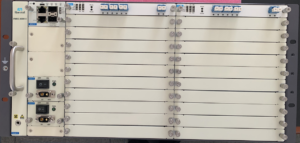
Side view of the central office equipment FMOC-6000 V of the semi-active WDM system
Description: 1) Each port has an independent indicator light;
2) The LC flange of the service card has a 45-degree oblique or straight port, which is convenient for customers to choose the plugging and unplugging methods of different optical fiber connectors;
3) Can be plugged into two DC power supplies or two AC power supplies.
Device panel slot distribution:
| Fan | Slot23 MMCC main control card | Slot1 general service card | Slot2 general service card |
| Slot3 general service card | Slot4 general service card | ||
| Back-up MMCC main control card | Slot5 general service card | Slot6 general service card | |
| Slot7 general service card | Slot8 general service card | ||
| Slot9 general service card | Slot10 general service card | ||
| Slot11 general service card | Slot12 general service card | ||
| Slot13 general service card | Slot14 general service card | ||
| Slot24 Power supply | Slot15 general service card | Slot16 general service card | |
| Slot17 general service card | Slot18 general service card | ||
| Slot25 Power supply | Slot19 general service card | Slot20 general service card | |
| Slot21 general service card | Slot22 general service card |
The FMOC-6000 V chassis of the central office equipment adopts a horizontal card structure, and all types of cards are pluggable at the front of the chassis; it provides 22 service card slots, 2 power card slots, 2 small main control slots, and 1 fan card slot.
4. OMC (network management software)
The OMC unified network management software needs to be developed and deployed based on the Microservice Architecture, and the B/S architecture provides external access clients. With the southbound Nentconf protocol, it can meet the security access of large-scale equipment. The main advantages are as follows:
- Easy to deploy; the system consists of multiple services with different functions. Components such as middleware, resources, performance, alarms, and services can be deployed or expanded according to different services;
- Easy to maintain; service components can be deployed independently, with functions such as horizontal expansion, elastic scaling, automatic upgrade, and grayscale release;
- Easy to expand; expand the server and corresponding services according to the number of new devices on the existing network, and support more than 10,000 devices.
The OMC management and control software realizes the management, maintenance, and test query analysis of the resources, faults, performance, configuration, topology, security, protection, system, data, etc. of the entire network system. It has the advantages of more stable operation, more access devices, better scalability, more powerful functional modules, more flexible data configuration, more compatible service cards, and stronger security.
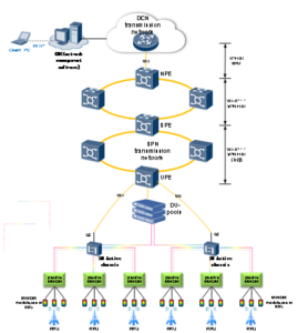
In this way, the centralized operation and maintenance management of transmission is more effectively promoted, and a set of management and control systems can intensively control multiple front-haul semi-active devices, creating a “one-stop” efficient operation and maintenance system, and helping the rapid transformation of intelligent operation and maintenance. The OMC software can also realize centralized management of semi-active equipment, whole process management, visual topology management, service quality tracking management, system security management, and other capabilities. The structure of the management and control system and the schematic diagram of the network architecture of the fronthaul and backhaul construction are as follows:
5. The OAM function is divided into the physical layer, link layer, and service layer
5.1 OAM physical layer
The OAM physical layer processes the physical layer of OAM data, including physical layer encoding and decoding and physical layer modulation and demodulation. The OAM physical layer includes two sublayers, the OAM modulation sublayer, and the OAM coding sublayer.
5.1.1 OAM modulation sublayer
The main function of the OAM modulation sublayer is to modulate digital information into the optical layer signal and demodulate the digital signal from the optical layer signal. The mechanism is the amplitude modulation (AM) mechanism.
The OAM processing pilot tone loss should be ≤0.5dB, and when the receiving optical power of the optical module is 5dB lower than the receiving sensitivity, the OAM frames of the single board and the optical module can be correctly received.
5.1.2 OAM coding sublayer
The OAM coding sublayer adopts Manchester coding: the low-high electrical level transition is represented as 0, and the high-low electrical level transition is represented as 1.
5.2 OAM link layer requirements
The OAM link layer realizes the encapsulation and decapsulation functions of OAM frames and achieves frame synchronization. The encapsulation process is: it encapsulates according to the OAM frame format, after the OAM link layer obtains the OAM payload content from the OAM service layer,
Link layer frame rate requirements: When using the amplitude modulation mechanism, the OAM link layer data rate is 1024bps; the rate accuracy is ±30bps, and the bit error rate (BER) is 1E-8.
5.2.1 Link Layer State Machine
The state of the OAM optical module includes frame synchronization and normal receiving and transmitting OAM state. The state machine is shown in the following figure. The module first performs frame synchronization and sends keeplive synchronized packets or other actively reported packets in the frame synchronization state. After receiving 5 correct OAM packets in a row, it starts to send and receive OAM packets normally and sends OAM packets as needed.
If three consecutive OAM frame errors are received, a frame out-of-step alarm is generated and the frame synchronization state is entered. In the frame synchronization state, it continuously sends keeplive synchronization packets or actively reports packets, trying to re-enter the OAM state of sending and receiving.
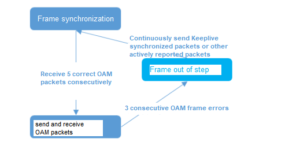
Schematic diagram of link layer state machine
OAM link layer supports data statistics functions, data including the number of frames sent and received, data rate, and the number of error frames.
5.3 OAM service layer requirements
The OAM service layer supports the OAM service query function, active reporting function, and reflection function.
5.3.1 OAM service layer supports query function
Configure the OAM query function through the semi-active MWDM management and control system, including querying the received optical power, transmitted optical power, current, voltage, temperature, wavelength, and module manufacturer information.
All messages with query function are initiated by the DU side module at the central office, and the remote AAU responds. After the central office sends a query message, the remote end sends a response message within 1 second. If the remote end receives a query packet when it is sending other packets (such as actively reporting packets), it needs to wait for the current packet to be sent and then respond to the query packet.
5.3.2 The OAM service layer supports the active reporting function
The active OAM reporting function is a periodic OAM message actively sent by the modules at both ends. The message content includes keeplive, LOS alarm, abnormal voltage and temperature alarm, and module manufacturer information.
In the case of module LOS, the active report message is normally sent periodically. The contents actively reported are as follows:
1) keeplive synchronization message
The keeplive synchronization message is sent by the modules at both ends during the idle period. The two ends can know that the optical module at the opposite end is in a normal working state and send and receive synchronization frames through the keeplive message. If the keeplive message is not received, a frame out-of-step alarm is generated and the state is given feedback.
2) LOS alarm
When the received optical power of the optical module is lower than the LOS threshold, the optical module should immediately send a LOS alarm message. When the LOS alarm is cleared, it will send a LOS alarm clearing message. To ensure that the central office can receive the message correctly, the message should be sent 3 times continuously.
3) Abnormal alarm of optical power, voltage, temperature, etc.
When the abnormal alarm of the optical power, voltage, or current is triggered or the alarm is cleared, the optical module should immediately send the optical module status frame and the alarm setting or clear the alarm status. To ensure that the central office can receive the message correctly, the message should be sent 3 times continuously.
4) Module status information
The module status information is periodically sent by the optical module, and the sending frequency is once every 3 minutes.
5) Module information
The module information is sent periodically by the optical module, and the sending frequency is once every 10 minutes.
5.3.3 OAM service layer reflection function
The optical module supports the reflection function. The AAU-side optical module sends its OAM information through the MUX/DEMUX devices at both ends to the DU-side optical module, and the DU-side optical module re-transmits the OAM information to the AAU-side optical module through the MUX/DEMUX devices at both ends.
The semi-active MWDM device can receive the OAM information from the AAU optical module through the information sent by the DU optical module. The reflected messages include LOS alarms of actively reported messages, abnormal alarms of voltage and temperature, module status information, module information, etc. The implementation requirements of the reflection function are shown as follows.
The implementation of the reflection function meets the following requirements:
1) The optical module in the fronthaul control system will collect information about the port, including port information, voltage, current, power, LOS, etc.;
2) The optical module encapsulates the information into the OAM frame and sends it to the optical path through modulation;
3) After the optical module receives the OAM information through demodulation, it will judge whether it is consistent with the local module ID through the OAM information module ID. If it is consistent, it will not be processed. If it is inconsistent, the OAM message will be resent to the opposite end module;
4) The active device parses the OAM information of each pair of optical modules.
6. OAM information accuracy
The requirements of optical module OAM information accuracy are as follows:
1)The accuracy error of receiving and transmitting optical power is ≤2dB;
2)Temperature accuracy error≤3℃;
3)Voltage accuracy error ≤3%;
4)Current accuracy error ≤10%.