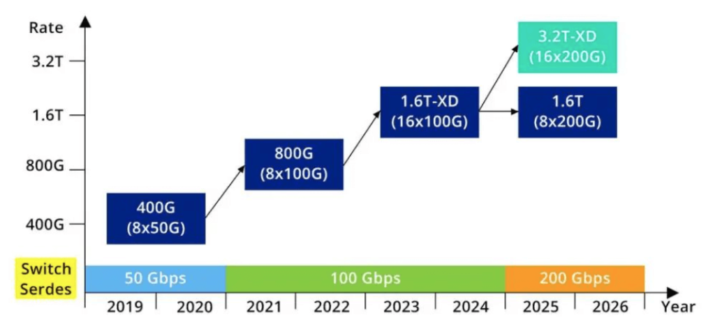
Traditional optical modules are independent of the switching ASIC and connected to other electronic components through copper cables or optical fibers. This approach often leads to significant power consumption and signal loss during high-speed data transmission. Particularly, as network speeds have progressed from 400G to 800G and even 1.6T, and are expected to reach 3.2T shortly, the power consumption challenge has become more pronounced.
The power consumption of SFP modules is around 2W, 100G optical modules are typically 1.5W to 3W, 400G QSFP-DD DR4 optical modules can be controlled within 12W, and 800G optical modules range from 12W to 16W.
As the data rates increase, the power consumption of individual optical modules has been rising linearly, leading to a significant increase in overall system power consumption.
From the device packaging perspective, when the signal rate doubles from 56Gbps to 112Gbps, the insertion loss of the low-loss PCB traces, even with advanced PCB materials, will also approximately double for a given trace length.
Generally, the shorter the electrical channel and the fewer the intermediate conversions (vias, connectors), the easier it is to manage signal integrity issues. This has driven the trend of integrating optical devices closer to the ASIC, which can effectively reduce power consumption.
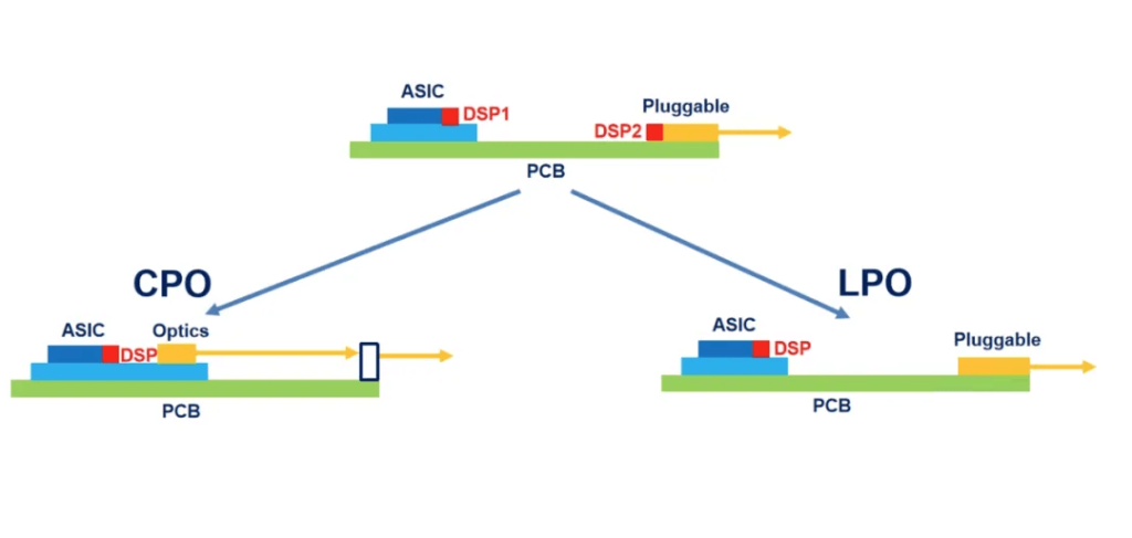
Two main solutions have emerged based on this principle:
- Co-Packaged Optics (CPO): Optical and electrical components are co-packaged.
- Linear Photonic Optical (LPO): Pluggable modules with linear optical drivers.
The evolution from pluggable modules to CPO and LPO is illustrated in the diagram.
What is Co-Packaged Optics (CPO)?
As mentioned earlier, traditional optical modules are independent of the switching ASIC and connected to other electronic components through copper cables or optical fibers. This approach often leads to significant power consumption and signal loss during high-speed data transmission.
CPO is a solution to address this issue. By co-packaging the optical module and the switching ASIC closely together, the distance for signal conversion between electrical and optical domains, as well as the transmission distance, can be greatly reduced. This can significantly lower power consumption, improve signal integrity, and reduce latency, while also reducing the overall footprint.
The diagram below illustrates the evolution from traditional copper-based DACs and pluggable optical devices to 3D-integrated optical devices in CPO.
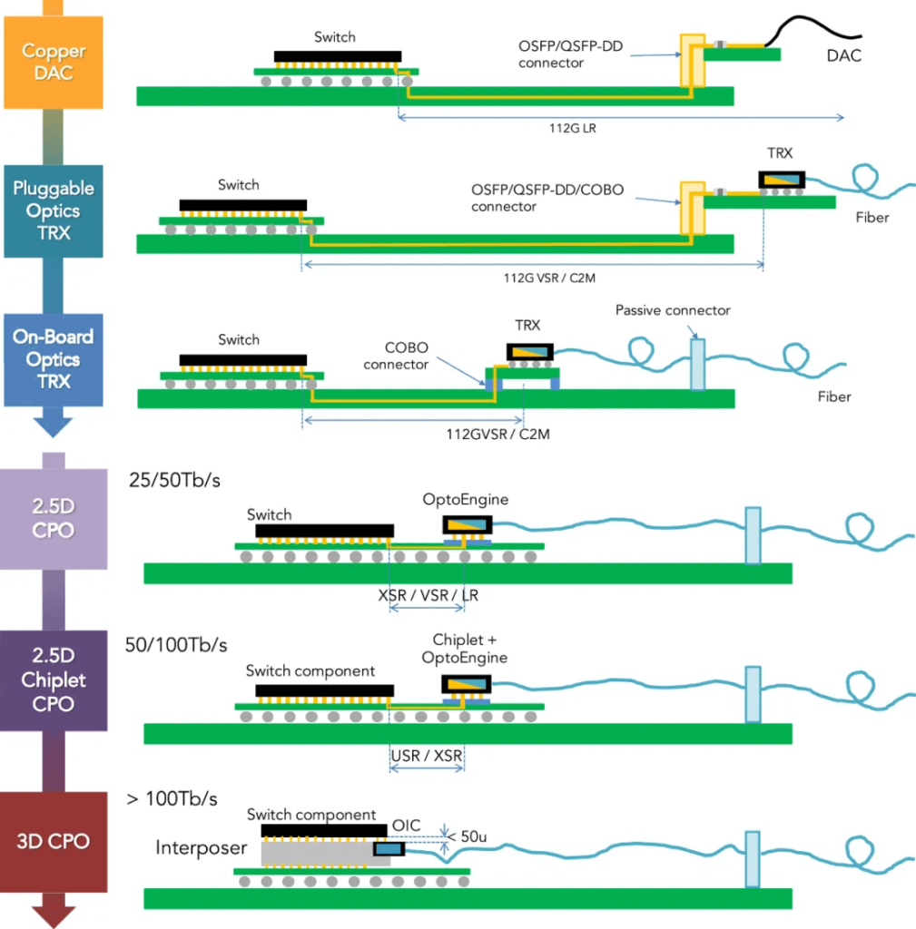
As you can see from the diagram above, it’s not a one-step process when it comes to how to minimize the linear distance of the connection, starting with NPO near-package optics and then CPO.
NPO decouples the optical engine from the switch chip and then assembles them on the same system board.
CPO, on the other hand, directly assembles the switching chip and the optical engine in one slot, realizing the co-packaging of the chip and the module.
Compared to NPO, CPO’s module is closer to the host ASIC, enabling lower channel loss and power consumption.
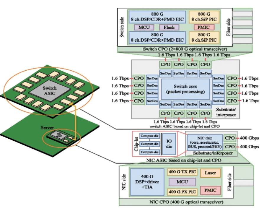
Currently, there are three stages of CPO (Chip-Photonics Optics) packaging:
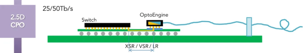
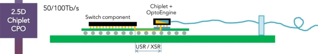
A-type CPO (corresponding to the 4th stage from top to bottom in Figure 3 – 2.5D CPO)
B-type CPO (corresponding to the 5th stage from top to bottom in Figure 3 – 2.5D Chiplet CPO)
C-type CPO (corresponding to the 6th stage from top to bottom in Figure 3 – 3D CPO)
From A-type to C-type, the key feature is that the optical engine and the switch ASIC are placed closer and closer together.
At this year’s OFC, major companies like Intel and Cisco showcased A-type CPO products. The A-type CPO is characterized by the chip and optical module being completely standardized and independent components, co-packaged on a PCB substrate. The distance between the optical engine and the chip is within 10cm, and the oDSP is eliminated.
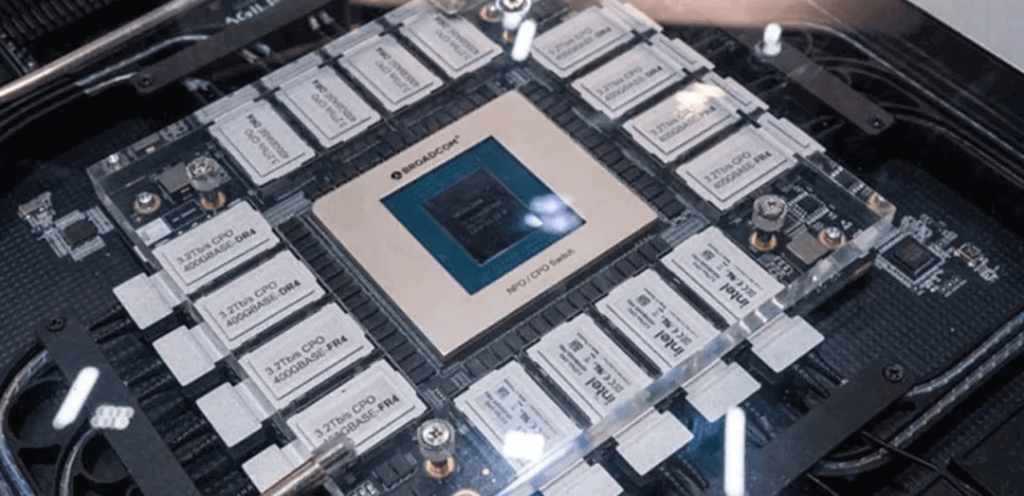
At OFC, Broadcom showcased its Bailly 51.2T switch using the B-type CPO solution, with 8 6.4T-FR4 Bailly SCIP optical engines and Broadcom fiber connectors (BFC). The difference from A-type CPO is not significant – the ASIC and optical module are still relatively decoupled, but wafer-level packaging technology is introduced to bring the two components closer, with a distance of just a few centimeters.
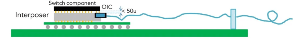
The C-type 3D CPO packaging is the ultimate form of CPO, truly integrating the silicon photonics chip with other bare dies (such as GPU, Lanswitch, HBM, etc.) in a single large package.
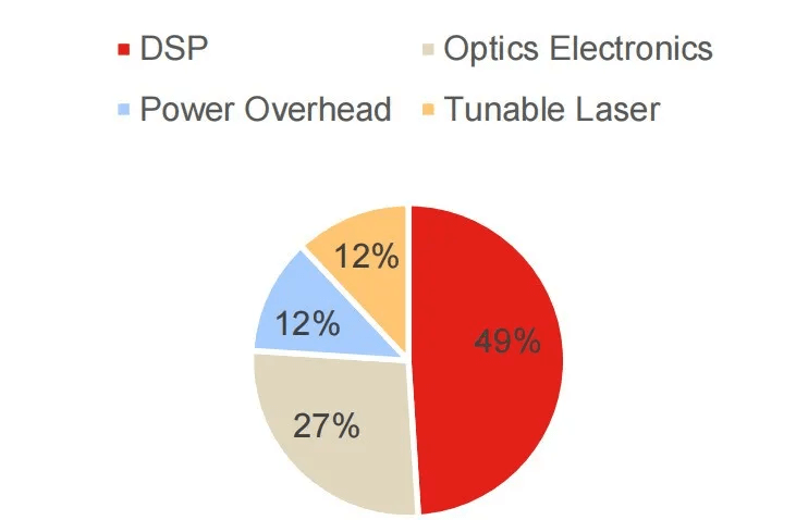
One of the goals of CPO is to reduce power consumption. As shown in Figure 2, the power consumption of a 400G ZR optical module is mostly concentrated in the DSP. So whether it’s CPO or the later discussed LPO, the core design is to eliminate the DSP.
However, we cannot say that CPO has no DSP. To realize high-speed signal modulation/demodulation, encoding/decoding, and signal compensation, CPO still needs to integrate DSP functionality or work closely with a chip with DSP capabilities. In the CPO solution, the DSP is either directly integrated on a chip within the package, or tightly connected through an extremely compact and efficient connection to achieve the required signal processing functions.
What is LPO Technology
LPO, or Linear-drive Pluggable Optics, is an optical module packaging technology. Whether it’s CPO or LPO, one of the main goals compared to traditional optical modules is to reduce power consumption, and the power consumption of the DSP is the highest among the entire module.
For LPO, the key characteristic is the elimination of the DSP. The data link only uses linear analog components, without any CDR or DSP design. It replaces the DSP with a Transimpedance Amplifier (TIA) and Driver (DRIVER) chip that have high linearity and equalization capabilities.
The ODCC released a white paper on 112G LPO optical module applications in 2023. The design of the LPO module is as follows:
- Removes the CDR/oDSP re-timer components
- Uses TIA and DRIVER chips with better performance and stronger SI compensation capabilities
- Integrates some compensation functions into the network device ASIC chip
- The signal regeneration and digital signal compensation originally done by the oDSP are now split between the network device ASIC, DRIVER, and TIA.
In terms of interfaces, LPO has no requirements for the module packaging, whether it is QSFP, QSFP-DD, OSFP, OSFPXD, or others, LPO solutions can be implemented.
In the industry, chip companies that are relatively weak in DSP, such as Macom, Semtech, and Maxlinear, are actively promoting LPO. The main reason is that they hope to bypass the DSP shortcomings through the LPO solution. Currently, the LPO solution standardization is not yet mature, mainly involving the electrical interface and optical interface.
The electrical interface is mainly the OIF’s CEI-112G-Linear-PAM4 protocol. As of the last update in April 2024, the CEI-112G-Linear-PAM4 standard has made substantial progress and has been adopted and implemented by the industry, with companies like Hisense already launching 800G linear interconnect optical cables based on this standard.
For the optical interface, the IEEE802.3 series protocols are mature and widely used standards, and all retimer-type pluggable optical modules need to comply with these protocols. If LPO can comply with the 802.3 protocols, it can achieve true “interoperability” in the fullest sense.
The Differences Between CPO and LPO
Both CPO and LPO are still under continuous development. CPO and LPO packaging each have their characteristics and advantages. CPO packaging technology focuses on integrated optical-electrical packaging, suitable for high-speed, high-density interconnect scenarios, while LPO packaging technology focuses on pluggability and cost-effectiveness, suitable for short-distance transmission scenarios. Within the CPO framework, if the system equipment fails, the power needs to be turned off and the entire board needs to be replaced, which is quite inconvenient for maintenance tasks.
In comparison, the pluggability of LPO optical modules allows for efficient replacement without shutting down the entire system, further enhancing the overall convenience of the LPO solution and simplifying fiber cabling and equipment maintenance.
Overall, LPO is an evolutionary path for pluggable optical modules, easier to implement and with more certainty compared to the CPO solution.
However, according to some experts, LPO technology introduces important design challenges for the electrical channel on the system side. The current mainstream SerDes specification is 112G, which will soon be upgraded to 224G. Experts believe that LPO technology may not be able to meet the requirements of 224G SerDes.
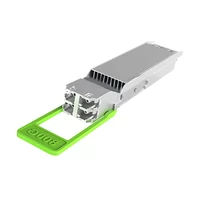
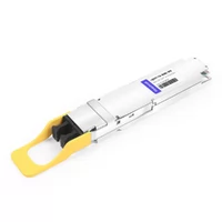
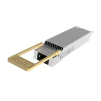
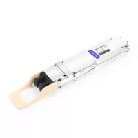
Related Products:
-
 LOSFP-800G-2FR4L LPO OSFP 2x400G FR4 PAM4 1310nm 2km DOM Dual Duplex LC SMF Optical Transceiver Module
$3500.00
LOSFP-800G-2FR4L LPO OSFP 2x400G FR4 PAM4 1310nm 2km DOM Dual Duplex LC SMF Optical Transceiver Module
$3500.00
-
LOSFP-800G-DR8D 800G LPO OSFP DR8 PAM4 1310nm 500m DOM Dual MTP/MPO-12 SMF Optical Transceiver Module
$1800.00
-
LOSFP-800G-SR8 LPO OSFP 8x100G SR8 PAM4 850nm MTP/MPO-16 50m OM4 MMF FEC Optical Transceiver Module
$1100.00
-
LOSFP-800G-SR8D LPO OSFP 8x100G SR8 PAM4 850nm 50m DOM Dual MPO-12 MMF Optical Transceiver Module
$1000.00
-
LQSFP-DD-800G-2FR4L LPO QSFP-DD800 2x400G FR4 PAM4 CWDM4 2km DOM Dual Duplex LC SMF Optical Transceiver Module
$1800.00
-
LQSFP-DD-800G-DR8D 800G LPO QSFP-DD800 DR PAM4 1310nm 500m DOM Dual MPO-12 SMF Optical Transceiver Module
$1500.00
-
LQSFP-DD-800G-SR8 800G SR8 LPO QSFP-DD 850nm 50m OM3 MMF MPO-16 Optical Transceiver Module
$1300.00
-
LQSFP-DD-800G-SR8D 800G SR8 LPO QSFP-DD 850nm 50m OM3 MMF 2xMPO-12 Optical Transceiver Module
$1300.00
-
LQSFP112-400G-DR4 400G LPO QSFP112 DR4 PAM4 1310nm 500m MTP/MPO-12 with KP4 FEC Optical Transceiver Module
$1200.00
-
LQSFP112-400G-SR4 400G LPO QSFP112 SR4 PAM4 850nm 50m MTP/MPO-12 OM3 FEC Optical Transceiver Module
$800.00