Overview of High-Speed Copper Cable Applications
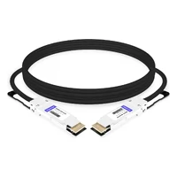
High-speed copper cables are a well-established technology used for many years in various domains such as computing, storage, and communication. They typically provide high-speed electrical signal interconnectivity between different device I/O interfaces using standard products. High-speed copper cables have evolved from coaxial cables to twinax cables specifically designed for high-speed differential signal transmission, rather than structured cabling using twisted-pair wires commonly used for Gigabit Ethernet networks.
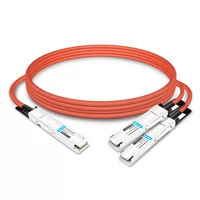
In the early days, high-speed copper cables were referred to as Direct Attach Cables (DAC), which are passive cables directly connected between devices. However, as the required transmission rates increased, the loss of copper cables became significant and could not meet the interconnection length requirements. This led to the introduction of Active Copper Cables (ACC), which are active cables. ACC incorporates a linear Redriver component at the Rx end of the cable to provide signal equalization and reshaping, thereby extending the end-to-end transmission distance. With the advent of the next-generation 56G-PAM4 link requirements, the lower Signal-to-Noise Ratio (SNR) under PAM4 modulation resulted in limited transmission distances supported by DAC and ACC. To address this, the industry introduced Active Electrical Cables (AEC). AEC includes Clock Data Recovery (CDR) components at both ends of the cable for retiming and re-driving the electrical signals. AEC generally has stronger compensation capabilities for copper cable losses and effectively blocks the propagation of jitter, allowing for longer end-to-end connection distances compared to ACC. From a system perspective, AEC is similar to Active Optical Cable (AOC) in terms of electrical interfaces because both are perceived as CDR chips within modules. The difference lies in the fact that AEC maintains electrical signal transmission between the CDRs at both ends. At the same time, AOC involves electrical-optical-electrical conversion and supports transmission distances of up to 30 meters using multimode fiber, surpassing the capabilities of AEC.
According to IDC data analyzing the global cloud market in 2019, the expenditure on the cloud computing market in the United States reached $124 billion. The North American cloud market continues to exhibit a sustained growth trend.
Demand for High-Speed Copper
The demand for high-speed copper cables, particularly DAC (Direct Attach Copper) compared to AOC (Active Optical Cable), has a significant impact on the overall stability and cost of the network within data centers. At the access layer, it is advisable to use more DAC, which offers simplicity, stability, and lower costs compared to other hardware options.
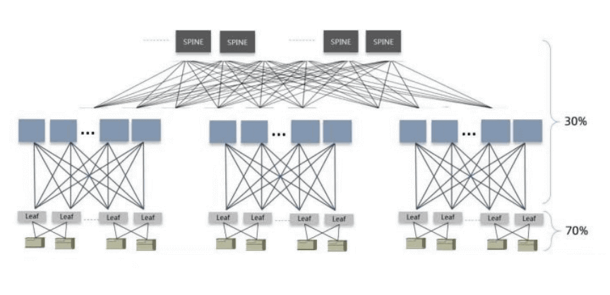
Typical Data Center CLOS Network Architecture Diagram
In recent years, with the self-construction and new construction of large and hyperscale data centers, advanced IDC integrated design has greatly increased the power capacity of individual server racks, thereby effectively reducing the vertical cabling distance for server access. With the deployment of white-box network devices and custom compute nodes, Direct Attach Copper (DAC) cables are widely used for server network connectivity within the rack. For 25Gbps links, DAC cables can cover transmission distances of up to 5m, while Active Copper Cable (ACC) can reach maximum transmission distances of around 7m to 9m, which is sufficient to meet the interconnection needs within the rack and some interconnections across racks.
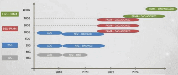
Trends in Link Technologies for Data Center Server Access Layer
Future development trends in terms of demand-driven aspects include exponential growth in east-west traffic in data centers, the separation of computing and storage, and the continuous development of hyper-converged networks. There will be an increasing demand for high bandwidth and high reliability in physical networks. At the same time, large-scale data centers require network scalability to achieve high deployment flexibility and delivery efficiency. Additionally, cloud computing businesses are highly cost-sensitive. Therefore, in terms of requirements, physical network interconnection needs to focus on hardware simplicity, convergence of product categories, efficient integrated delivery, and optimal link performance (such as achieving error-free levels at the physical layer).
From an application perspective, the design of data centers should be future-oriented, integrating IDCs, cabinets, servers, networks, and operations into a unified design. The goal is to decompose the optimal solution for each component under different business scenarios with the lowest total cost of ownership (TCO). For example, when considering factors such as access distance, server density, network port utilization, and link stability, the design should weigh options such as passive copper cables, active copper cables, or AOC (Active Optical Cables) for the server access layer.
High-Speed Copper Cable Technology
In the technical specifications of high-speed copper cables, industry-standardization organizations have defined corresponding standards for interface modules, interface connectors, and management interface standards. These standards include structural dimensions, electrical connections, management interface protocols, and other aspects. These parts need to be followed to ensure compatibility and interoperability between equipment, cables, and software systems.
The end-to-end signal integrity performance specifications of the cables are defined by organizations such as IEEE and OIF-CEI, which establish specification baselines and consistency testing requirements to meet the transmission implementation of different types of network physical layers and the compatibility between devices, modules, and cables. However, there are no standardized specifications for the implementation of key components that primarily determine the signal integrity performance of the cable, such as the bulk cable and module PCB, as well as the connection process. The materials, high-speed SI design, manufacturing processes, and other technologies involved in these components are the proprietary technologies of each cable manufacturer.
Interface and Cable Modules
For different application scenarios and application hierarchies, high-speed copper cables offer a diverse range of choices.

Interface Type and Lane
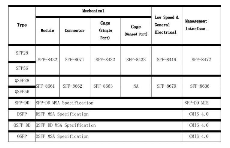
Interface Industry Standards
The following table summarizes the structural dimensions of the corresponding modules for each interface type, which correspond to the physical dimensions of the connectors and cages on the system side.
The dimensions of the module correspond to the physical dimensions of the connector and cage on the system side.
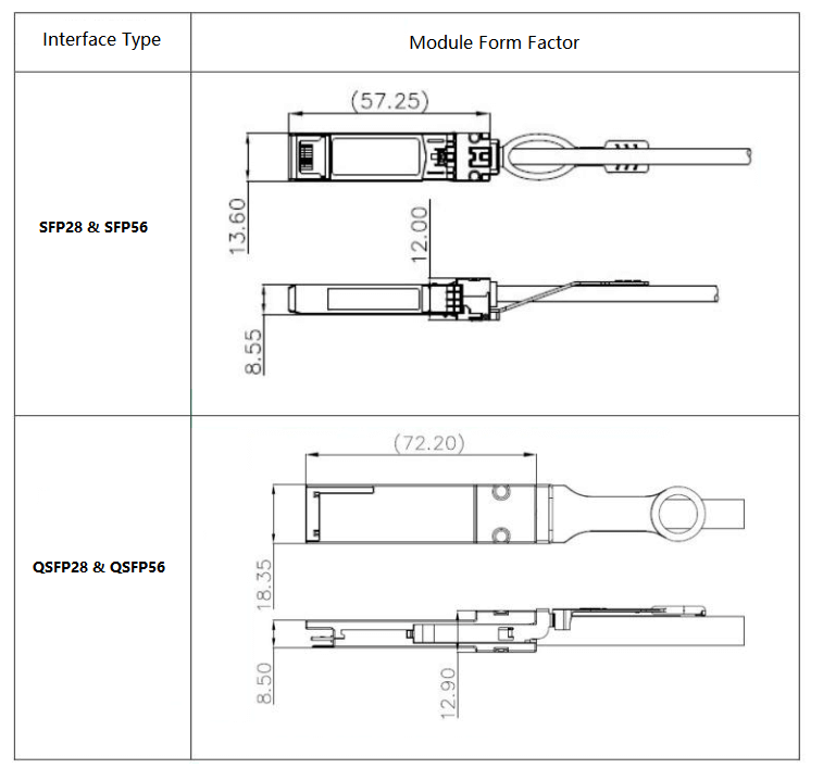
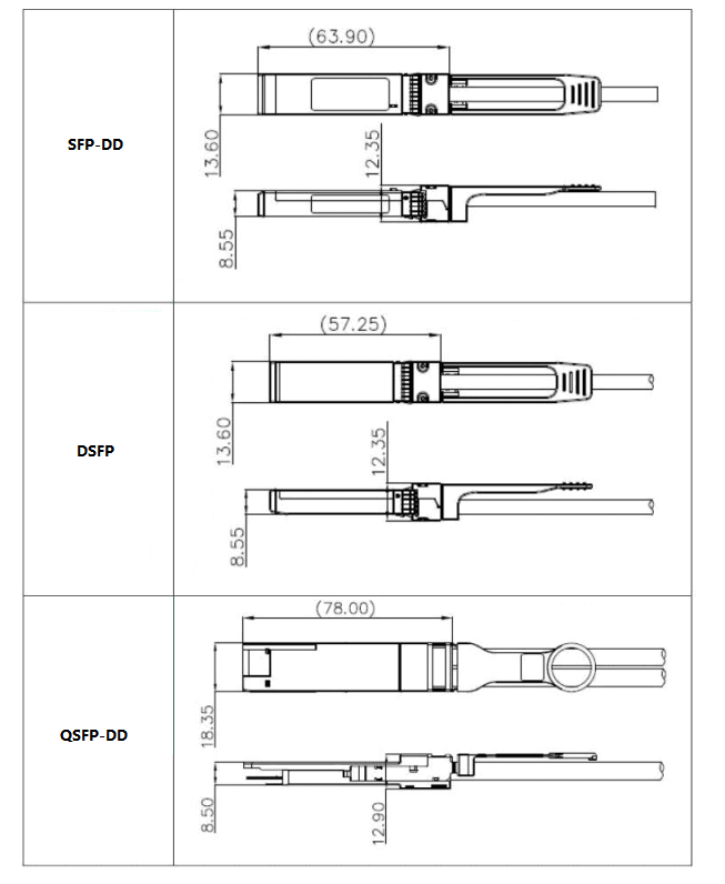
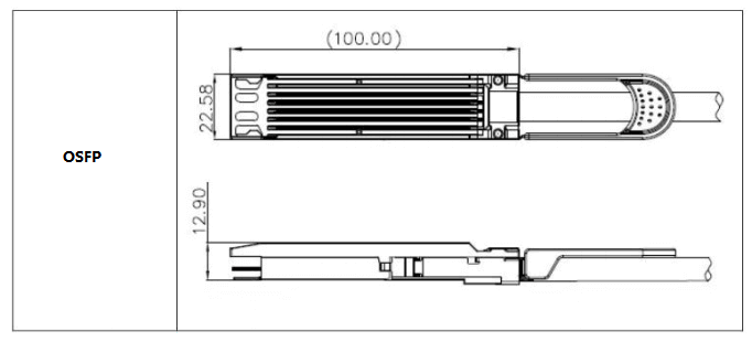
Module Form Factor
Cable Assembly Structure
The highly compatible high-speed copper cable iterations have enabled a high degree of similarity in interface forms for high-speed copper cables.
The iron shell structure of the metal alloy ensures the requirements for high electromagnetic compatibility while also providing strength for the interface. The design of a simple yet highly similar unlocking system guarantees stable migration and extensive application of the functionality. The table below provides explanations for various interface types.
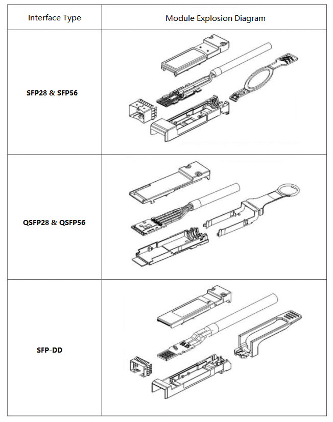
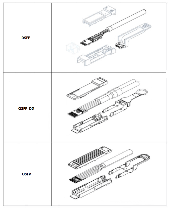
Comparison of Exploded Views
The cable is composed of silver-plated conductors and insulated cores, using a pair-to-screen and overall shielding configuration, thereby forming a high-speed cable. Typically, specifications ranging from 30 to 26 AWG are used, along with various structures such as 2 pairs, 4 pairs, or 8 pairs. Figure 3-8 illustrates the schematic diagram of a typical 2-pair cable. Table 3-8 provides the corresponding OD reference values for various typical structures and suitable finished product types. Different manufacturers design cable products with different ODs according to specific product requirements, such as signal integrity performance, flame retardancy, and application scenarios. These cables can be applied in various different application scenarios.
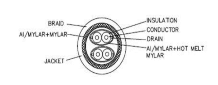
Cross-Section Diagram of a Typical 2-Pair Cable Assembly
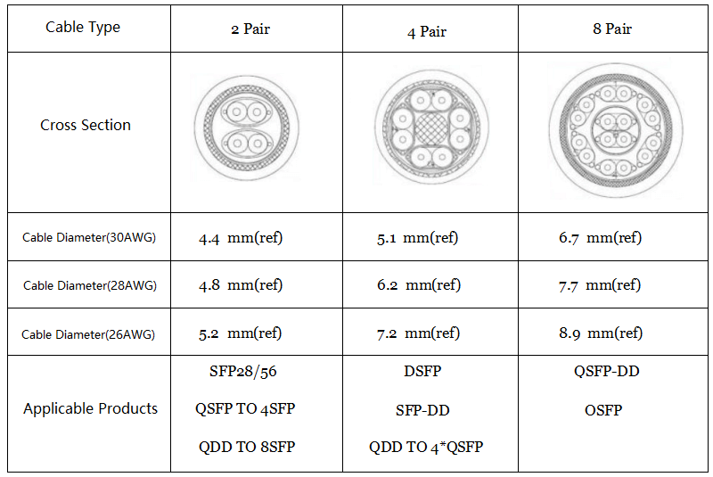
Comparison of Typical Dimensions for Different Cable Structures
Cable Reliability Specifications
In order to ensure good plug-in and transmission reliability of high-speed copper cable DAC products in various environments, manufacturers subject finished DAC products to a series of reliability tests. These tests verify connector dimensions, electrical performance, mechanical performance, environmental performance, safety performance, and other aspects according to different specifications.
Management Interface Standards
The types of management interfaces are influenced by changes in the electrical interface hardware during the evolution and derivation of port types. Additionally, the demand for management functions for modules with more complex features has led to the inadequacy of older-generation management interfaces, resulting in the emergence of new management interface standards. Table 3-13 provides standards for the management interfaces of different types of modules.
SFP56 Interface Standard
The SFP56 interface adopts the management interface standard of SFP28 and SFP+. The difference lies in the support for 56G-PAM4 in terms of data rate, encoding type, and high-speed physical layer protocol.
QSFP56 Interface Standard
The QSFP56 interface adopts the management interface standard of QSFP28 and QSFP+. Similar to SFP56, it supports 56G-PAM4 in terms of data rate, encoding type, and high-speed physical layer protocol.
SFP-DD/QSFP-DD/OSFP/DSFP Interface Standards
The SFP-DD, QSFP-DD, OSFP, and DSFP interfaces follow the definitions provided in the “Common Management Interface Specification Rev 4.0” for managing corresponding EEPROMs.
High-Speed Passive Copper Cable SI Specifications
56G-PAM4 Link SI Requirements
In order to achieve compatibility and interface consistency among various modules in the physical network link, such as network physical layer chips, hardware boards, connectors, copper cables, and optical modules, IEEE specifications have been established for the SI (Signal Integrity) performance specifications that each module needs to adhere to. These specifications include insertion loss, return loss, mode conversion, etc., and corresponding consistency test points are defined, as shown in Figures. These figures represent the insertion loss budget allocation and corresponding consistency test points for the 100G-CR4 and 200G-CR4 channels defined in IEEE802.3bj and IEEE802.3cd, respectively.
When transitioning from a 25G-NRZ link to a 56G-PAM4 link, there is a reduction in the entire end-to-end insertion loss budget from 35dB to 30dB due to SNR (Signal-to-Noise Ratio) losses caused by PAM4 modulation. Additionally, the insertion loss budget for copper cable end-to-end testing reduces from 22.48dB @ 12.89GHz to 17.16dB @ 13.28GHz, which is one of the significant changes. According to the IEEE specification, for the 56G-PAM4 physical link, Reed-Solomon (RS) coding with parameters RS(544,514) is used for forward error correction (FEC). The expectation is to achieve system-level end-to-end error rates lower than le-15 after FEC correction, with a pre-FEC bit error rate not exceeding 2.4e-4.
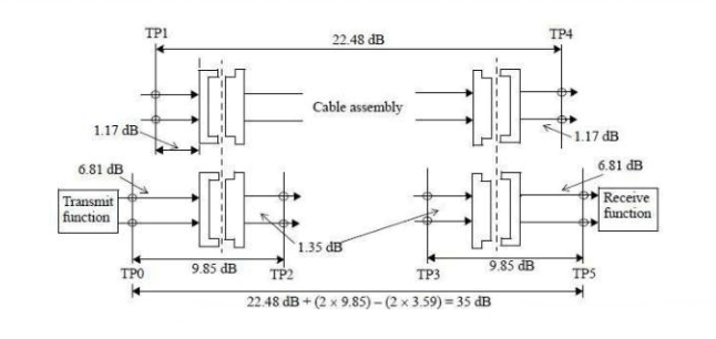
IEEE802.3bj 100GBase-CR4 Channel Insertion Loss Budget Allocation
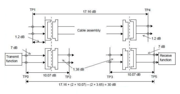
IEEE802.3cd 200GBase-CR4 Channel Insertion Loss Budget Allocation
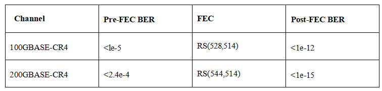
IEEE802.3 100GBASE-CR4 (25G-NRZ) vs. 200GBASE-CR4 (56G-PAM4) BER Specifications
In the current practical network environment, although a post-FEC bit error rate (BER) of le-15 is considered a good level of error correction, in large-scale deployment applications, end users such as data centers have higher expectations than this standard. There are two reasons for this. Firstly, high-performance networks require the physical layer of the network to achieve an extremely low error rate to support technologies like RDMA, which are highly sensitive to errors. The le-15 standard does not guarantee error-free performance over a measurable or perceivable length of time. Secondly, various factors affecting loss need to be considered when deploying at a large scale, such as cable bending, high temperatures, power fluctuations, and system crosstalk, all of which can degrade the overall system-level BER performance.
56G-PAM4 Passive Copper Cable SI Specifications
The figures shown below present the required characteristics of the cable itself and the corresponding actual cable test data (provided by Luxshare Technology) for the 200GBASE-CR4 channel defined in IEEE802.3cd. For a more detailed description and mathematical model, please refer to the IEEE802.3cd specification. It is important to note that these are design specifications based on unrestricted conditions. End-users need to be aware that there may be differences between the models or samples used for system-level signal integrity design or laboratory-level testing and the actual performance of cables when deployed in large-scale installations. It is necessary to quantify these differences in order to guide end-users in incorporating appropriate margin reserves during the initial stages of system-level interconnect design and considering constraints during deployment (e.g., environmental temperature, specified bending radii).
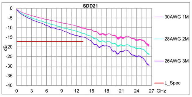
IEEE802.3cd 200GBASE-CR4 SDD21 Specifications and Test Data
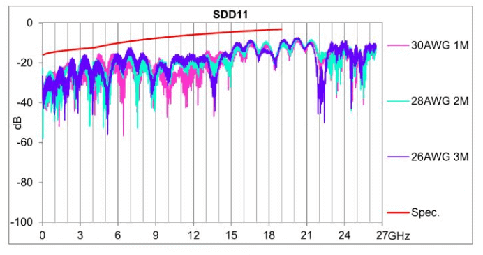
IEEE802.3cd 200GBASE-CR4 SDD11 Specification and Test Data
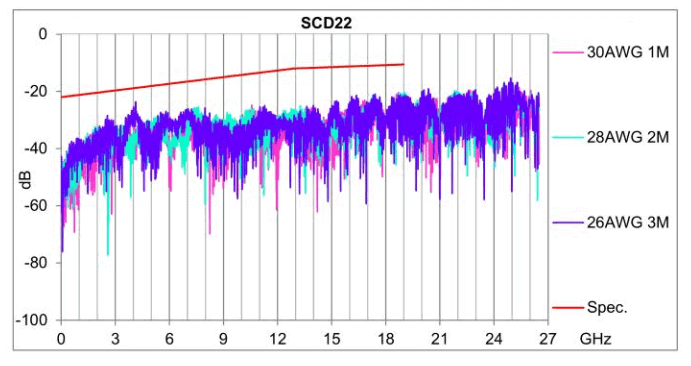
IEEE802.3cd 200GBASE-CR4 SCD22 Specifications and Test Data
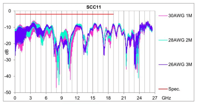
IEEE802.3cd 200GBASE-CR4 SCC11 Specification and Test Data
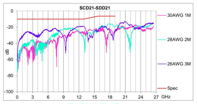
IEEE802.3cd 200GBASE-CR4 SCD21-SDD21 Specifications and Test Data
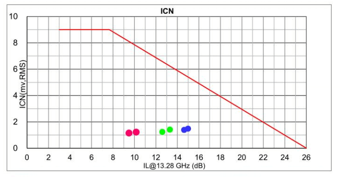
IEEE802.3cd 200GBASE-CR4 ICN Specifications and Test Data
The difference between the ideal cable model or sample and the actual performance in bulk deployment in real-world scenarios requires a quantitative analysis of various contributing factors. Based on the data gathered from the large-scale deployment of the previous generation 25G-NRZ DAC and limited testing of 56G-PAM4 DAC samples, the following factors have been identified as the main contributors to the differences: ambient temperature, cable bending, and immersion environment (such as air-cooling and immersion liquid-cooling environments).
The table below presents the FEC (Forward Error Correction) pre-FEC and post-FEC error rates obtained from loopback tests using 1m and 3m DACs with currently mature 56G-PAM4 SerDes chips. Both configurations demonstrated excellent performance, with post-FEC error rates well below 1e-15 (99.5% confidence level).
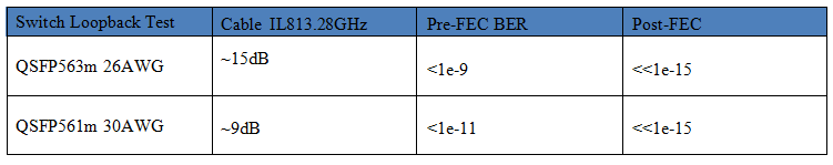
200G DAC Switch Loopback Test Sampling Results
High-Speed Active Copper Cable Technology
Active Copper Cable Design Principles
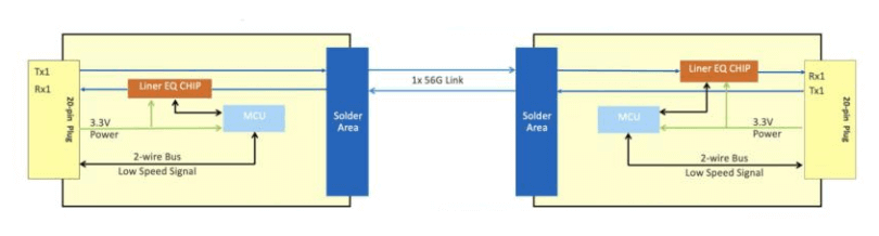
ACC (Liner EQ Chip Solution)
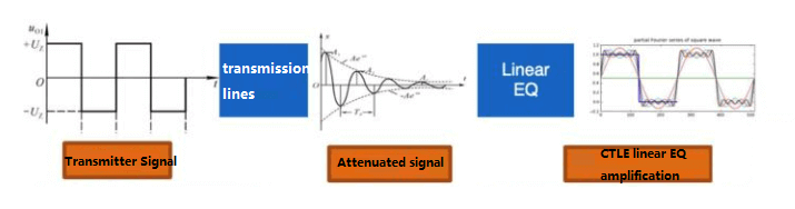
Schematic of ACC link transmission principle
Liner EQ solution adopts the CTLE high pass filter working principle, the gain attenuation remains unchanged at low frequency, the attenuation gain becomes larger as the frequency rises to compensate for the loss of high-frequency signals, and the attenuation gain slowly becomes smaller after a higher frequency, and through the superposition and combination settings of different CTLEs, the gain compensation of different frequency bands can be realized.
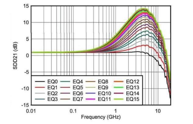
Typical Active CTLE Equalization Curve
Liner EQ solution only places the chip at the receiving end and compensates the high-frequency signal through CTLE, which simulates the attenuation parameters of conventional passive copper cable, and the system needs to recognize ACC (Liner EQ) as CR (passive copper cable) mode when identifying.
Liner EQ solution’s overall power consumption is small, with almost no additional consideration of heat dissipation.
Liner EQ transmits signals with undifferentiated gain, which amplifies noise (reflected in crosstalk data) while compensating for attenuation.
- Block diagram of a typical application (SFP56 as an example)
SFP56 ACC Schematic Block Diagram
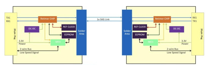
5.1.2 AEC (Retimer Chip Solution)
- AEC (Retimer) schematic block diagram:
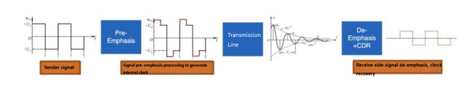
Schematic diagram of AEC link transmission principle
When the signal passes through the Retimer, the Retimer will reconstruct the signal through the internal clock to increase the energy of the transmitted signal, and after the transmission line is attenuated, the data will be recovered through the reconstructed clock signal, so as to achieve the effect of attenuation gain.
- Block diagram of a typical application (take SFP56 as an example)
SFP56 AEC Block Diagram
5.2. 56G-PAM4 Active Copper Cable Technical Specifications
5.2.1. ACC (Liner EQ chip solution)
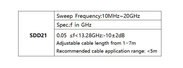
In general, ACC and DAC have the same SI parameter requirements, but the SI parameter requirements can be normalized to some extent by adjusting the chip, for example, for the actual 50G PAM4/lane rate application, the cable specification can be constrained to the following range, and the actual test results are shown in the following test data.
Active ACC SI Specifications
Test Setup:
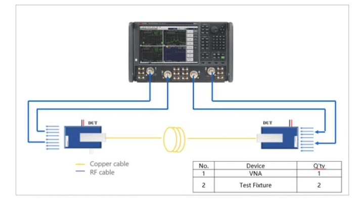
ACC S Parameter Test Setups
AEC (Retimer Chip Solution)
- SI specification requirements
AEC solution is similar to AOC in its working principle, the signal reaches the equipment through clock recovery, and it needs to meet the BER and eye diagram requirements according to the OIF-CEI-VSR specification. OIF-CEI-04.0 CEI-56G-VSR-PAM4 Very Short Reach Interface requires a BER of less than 1e-6 for No-FEC.
The specifications of the output eye diagram at the AEC module are shown in the table below, and you can refer to the OIF-CEI-VSR-PAM4 datasheet for detailed specifications. The length of the copper cable that can be supported by the AEC depends on the loss of the entire channel between the Retimer chips of the modules at both ends, as well as the signal equalization and compensation capability of the Retimer. Typically, both Retimers can support the CEI-56G-LR-PAM4 channel, i.e., 30dB@14GHz. Therefore, the length of the copper cable between the Retimers at both ends of the module needs to be adjusted according to the chip’s capability.
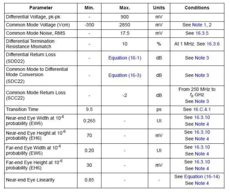
OIF-CEI-56G-VSR-PAM4 Module Output Eye Diagram Specification
- Eye diagram test setup:
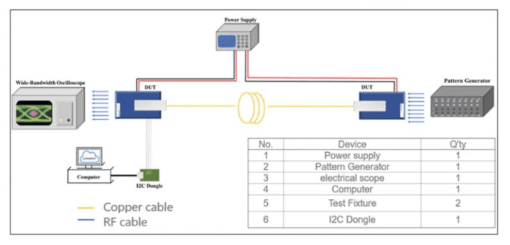
OIF-CEI-56G-VSR-PAM4 Module Output Eye Diagram Test Setting
- AEC (Retimer) Measured Data – – – Module Output Eye Diagrams
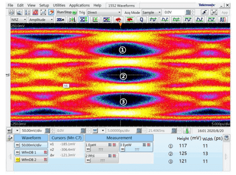
AEC module output 56G-PAM4 electrical eye diagram
Conclusion
With the large-scale deployment of 25G DAC and ACC by large data center users, it lays a good foundation for the application of high-speed copper cables in the future 200G/400G data center network. Downstream users have accumulated successful experience in the deployment and operation of high-speed copper cables, and the scale of deployment has been enlarged, thus promoting the technology evolution and ecosystem maturity of upstream vendors, and a positive ecological development has been formed, especially FiberMall has demonstrated its excellent technical capability and supply capacity.
Based on the experience of large-scale deployment of the previous generation of 25G copper cables, FiberMall provides data center users, high-speed copper cable vendors, equipment vendors, etc. with a basic reference of high-speed copper cable technology, application, etc., before the application of the next generation of 56G-PAM4 in large-scale, which will come soon. It is hoped that this will help the whole industry chain to be more competitive in the application of the next generation of new technologies.
Related Products:
-
 SFP28-25G23-BX10I 25G BX BIDI SFP28 TX1270nm/RX1330nm 10km LC SMF DDM Industrial Transceiver Module
$50.00
SFP28-25G23-BX10I 25G BX BIDI SFP28 TX1270nm/RX1330nm 10km LC SMF DDM Industrial Transceiver Module
$50.00
-
SFP56-50G-LRC 50G SFP56 LR 1311nm PAM4 Duplex LC SMF 10km DDM Optical Transceiver Module
$295.00
-
QSFP28-100G-SR4 100G QSFP28 SR4 850nm 100m MTP/MPO MMF DDM Transceiver Module
$40.00
-
QSFP28-100G-IR4 100G QSFP28 IR4 1310nm (CWDM4) 2km LC SMF DDM Transceiver Module
$110.00
-
QSFP56-200G-SR4M 200G QSFP56 SR4 PAM4 850nm 100m MTP/MPO APC OM3 FEC Optical Transceiver Module
$139.00
-
QSFP56-200G-FR4S 200G QSFP56 FR4 PAM4 CWDM4 2km LC SMF FEC Optical Transceiver Module
$650.00
-
QSFP-DD-400G-SR8 400G QSFP-DD SR8 PAM4 850nm 100m MTP/MPO OM3 FEC Optical Transceiver Module
$149.00
-
QSFP-DD-400G-LR4 400G QSFP-DD LR4 PAM4 CWDM4 10km LC SMF FEC Optical Transceiver Module
$600.00
-
OSFP-400G-SR4-FLT 400G OSFP SR4 Flat Top PAM4 850nm 30m on OM3/50m on OM4 MTP/MPO-12 Multimode FEC Optical Transceiver Module
$550.00
-
OSFP-400G-DR4 400G OSFP DR4 PAM4 1310nm MTP/MPO-12 500m SMF FEC Optical Transceiver Module
$800.00
-
OSFP-800G-SR8 OSFP 8x100G SR8 PAM4 850nm MTP/MPO-16 100m OM4 MMF FEC Optical Transceiver Module
$650.00
-
OSFP-800G-FR8 OSFP 8x100G FR PAM4 1310nm MPO-16 2km SMF Optical Transceiver Module
$1200.00
-
NVIDIA MCA7J60-N004 Compatible 4m (13ft) 800G Twin-port OSFP to 2x400G OSFP InfiniBand NDR Breakout Active Copper Cable
$800.00
-
QDD-OSFP-FLT-AEC3M 3m (10ft) 400G QSFP-DD to OSFP Flat Top PAM4 Active Electrical Copper Cable
$1700.00
-
QSFP28-100G-PC1M 1m (3ft) 100G QSFP28 to QSFP28 Copper Direct Attach Cable
$25.00
-
NVIDIA(Mellanox) MCP1600-E01AE30 Compatible 1.5m InfiniBand EDR 100G QSFP28 to QSFP28 Copper Direct Attach Cable
$35.00
-
QSFPDD-400G-PC1M 1m (3ft) 400G QSFP-DD to QSFP-DD PAM4 Passive Direct Attach Copper Twinax Cable
$75.00
-
QSFP-DD-400G-AC3M 3m (10ft) 400G QSFP-DD to QSFP-DD PAM4 Active Direct Attach Copper Twinax Cable
$350.00