

The three high-density pluggable form factors relevant to 400G, 800G, and next-generation AI networks are QSFP-DD, OSFP, and the newly announced USFP design. QSFP-DD offers broad backward compatibility with supported legacy QSFP modules, OSFP provides a larger form factor with integrated heatsink options and support for higher-power module generations, and USFP is a proposed 400 Gb/s-per-electrical-lane design announced by NVIDIA and Cisco in October 2026. USFP’s final specification and product availability are still under development.
In brief, QSFP-DD is often a practical choice for Ethernet upgrades where legacy QSFP-module support matters. OSFP may be a better fit when the selected switch platform requires its form factor or benefits from its thermal design. USFP is worth tracking for future AI fabrics, but it should not yet be treated as a finalized, commercially available standard.
What Are QSFP-DD, OSFP, and USFP?
Before comparing them side by side, it helps to understand what each form factor offers. The names reflect their form-factor families and, in some cases, lane density; they are not a universal rule for determining the number of lanes.
QSFP-DD: Quad Small Form-Factor Pluggable, Double Density
QSFP-DD stands for Quad Small Form-Factor Pluggable Double Density. It extends the QSFP family from four to eight high-speed electrical lanes, which is the basis of the “double density” name.
A QSFP-DD module is approximately 18.35 mm wide, 8.5 mm high, and 89.4 mm long. A QSFP-DD host port is designed to support compatible legacy QSFP-family modules, such as QSFP+, QSFP28, and QSFP56, subject to the host platform’s specifications. This compatibility can help operators migrate in stages. It does not mean that a QSFP-DD module can be inserted into an older QSFP cage.
The QSFP-DD family supports multiple generations, including 400G (8 × 50G), 800G (8 × 100G), and 1.6T in QSFP-DD1600 implementations (8 × 200G). Actual module rates, power requirements, and thermal limits depend on the module generation and host platform.
OSFP: Octal Small Form-Factor Pluggable
OSFP stands for Octal Small Form-Factor Pluggable. The standard OSFP form factor uses eight high-speed electrical lanes and was designed with thermal management in mind. Standard OSFP modules have an integrated heatsink; other variants, such as OSFP-RHS, use a separate host-side cooling solution.
An OSFP module is larger than a QSFP-DD module, measuring approximately 22.58 mm wide, 13 mm high, and 107.8 mm long. The larger form factor and heatsink options can support higher-power modules, but actual thermal performance depends on the module, switch airflow, heatsink design, and host-system limits.
The trade-off is mechanical compatibility. OSFP modules are not directly interchangeable with QSFP cages. Some host platforms can support selected legacy QSFP modules through adapters, but that support is platform-specific. OSFP is used in high-performance Ethernet and InfiniBand systems, including AI and high-performance computing environments, where the selected platform’s bandwidth and thermal requirements make it suitable.
USFP: Ultra-Dense Small Form-Factor Pluggable
USFP stands for Ultra-Dense Small Form-Factor Pluggable. On October 12, 2026, NVIDIA and Cisco announced design plans for USFP as a high-density pluggable form factor designed to support 400 Gb/s-per-lane electrical signaling. The announcement describes a proposed design and an ecosystem-development effort, rather than a completed industry specification.
The first planned USFP design uses 16 full-duplex lanes in an OSFP-sized footprint and is intended to support both switches and SuperNICs. At 400 Gb/s per lane in each direction, 16 lanes correspond to 6.4 Tb/s in each direction, or 12.8 Tb/s when transmit and receive capacity are added together. Capacity figures should always state whether they represent one direction or the sum of both directions. The architecture is intended to scale to 32 or more lanes in future designs, subject to the final specification.
USFP also introduces a two-dimensional array connector with a two-step insertion design. According to the announcement, the high-speed contacts engage after the module is inserted, a design intended to reduce contact wear, improve signal integrity, and make insertion force more predictable. The announced design supports power dissipation of up to 100 W without requiring a separate, dedicated cooling circuit inside the transceiver. This does not remove the need for system-level thermal management.
The USFP specification is planned to be developed through an upcoming community-led multi-source project. NVIDIA and Cisco are working with TE Connectivity and Amphenol on cages, connectors, and modules, with additional partners expected. The announcement did not specify a public sampling or general-availability date.
Want to see how these form factors fit into a broader optical roadmap? Explore FiberMall’s optical transceiver solutions.
USFP vs OSFP vs QSFP-DD: Specification Comparison
The table below summarizes the main differences. Values for announced or future designs should not be treated as finalized specifications, and actual support depends on the module and host platform.
| Specification | QSFP-DD | OSFP | USFP |
| Electrical lanes | 8 | 8 | 16 full-duplex lanes in the first planned design; future scaling to 32 or more |
| Per-lane signaling rate | 50 / 100 / 200 Gb/s across generations | 50 / 100 / 200 Gb/s across generations | Designed for 400 Gb/s per electrical lane |
| Family or announced capacity | Up to 1.6 Tb/s with QSFP-DD1600; product and platform support vary | Up to 1.6 Tb/s with OSFP1600; product and platform support vary | Announced design capacity of up to 12.8 Tb/s when both directions are counted |
| Approximate module size (W × H × L) | 18.35 × 8.5 × 89.4 mm | 22.58 × 13 × 107.8 mm | OSFP-sized footprint; exact dimensions depend on the final specification |
| Power and thermal design | Module- and host-dependent; high-power variants require appropriate thermal design | Up to 33 W for OSFP/OSFP800 and up to 42.9 W for OSFP1600 under the OSFP MSA specification; host support is required | Up to 100 W, as announced; final specification and host requirements are not yet published |
| Port / front-panel density | Up to 36 ports per 1U, depending on system design | Up to 36 ports per 1U, depending on system design | Vendor-stated 4× front-panel bandwidth density versus 200G-per-lane pluggables |
| Backward compatibility | A QSFP-DD host port can support compatible legacy QSFP-family modules, subject to platform support | Not mechanically interchangeable with QSFP cages; adapter support is platform-specific | New design; interoperability details depend on the upcoming specification |
| Primary use case | Enterprise and data-center Ethernet; 400G, 800G, and 1.6T migrations | AI/HPC, Ethernet, InfiniBand, and higher-power optics where supported by the platform | Proposed next-generation AI Ethernet fabrics; ecosystem in development |
Two points stand out. First, QSFP-DD and OSFP both support eight-lane designs and have specifications for 800G and 1.6T generations. Their differences are mainly mechanical, thermal, and platform-related—not a universal difference in bandwidth. Second, USFP targets a higher electrical lane rate, but its final specification, compatible silicon, and product availability remain under development.
Electrical Lanes and Speed: 200G vs. 400G Per Lane
To understand why USFP matters, it helps to understand per-lane speed and how manufacturers report aggregate bandwidth.
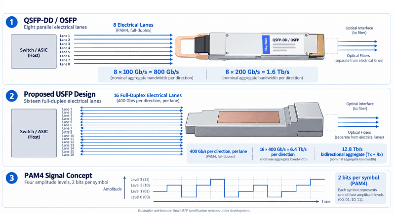
PAM4 Signaling and Why Per-Lane Rate Matters
Modern high-speed optical modules commonly use PAM4 signaling on electrical lanes. PAM4 encodes two bits per symbol, allowing more data to be carried at a given symbol rate than binary signaling. The nominal aggregate lane rate is calculated by multiplying the number of lanes by the per-lane rate. Usable payload throughput can differ because of coding, FEC, and protocol overhead.
QSFP-DD and OSFP can each support eight-lane architectures. At 100 Gb/s per lane, eight lanes provide a nominal 800 Gb/s; at 200 Gb/s per lane, eight lanes provide a nominal 1.6 Tb/s. USFP is designed to move to 400 Gb/s per electrical lane. In a 16-lane full-duplex configuration, that represents 6.4 Tb/s in each direction, or 12.8 Tb/s when both directions are added together.
Higher per-lane rates can reduce the number of lanes and electrical connections needed for a given bandwidth. This may simplify connector and cable design and improve bandwidth density, although overall cost and complexity also depend on signal integrity, optics, power, cooling, and the host platform.
The 400G-Per-Lane Leap
Current high-end switch silicon includes 200G-class SerDes designs. For example, NVIDIA Spectrum-6 specifies 200G PAM4 SerDes, while Cisco Silicon One G300 specifies 224 Gb/s SerDes. These are electrical signaling rates and should not be confused with nominal Ethernet port rates. USFP is designed for 400 Gb/s-per-lane electrical signaling, so adoption will depend on compatible switch silicon, host systems, transceivers, and ecosystem development.
USFP’s potential advantage is that it aims to extend the pluggable-optics model to higher lane rates and greater front-panel bandwidth density. It may offer an additional path alongside co-packaged optics (CPO), but it does not make CPO or other optical architectures obsolete. The relative merits will depend on the complete system design and deployment requirements.
Size, Port Density, and Thermal Design
The physical differences among these form factors influence system design, but no single form factor is automatically best for every switch or workload.
QSFP-DD Density and Backward Compatibility
QSFP-DD supports up to 36 ports per 1U front panel in suitable system designs. Its backward compatibility can help operators reuse supported QSFP-family modules in new QSFP-DD host ports while migrating parts of a network to higher speeds. Compatibility still depends on the switch platform, module coding, software, and supported operating modes.
QSFP-DD can be a practical option for enterprise and data-center Ethernet upgrades because of its broad ecosystem. However, actual port density and total system cost should be compared using specific switch models, airflow requirements, and supported transceivers rather than the form factor alone.
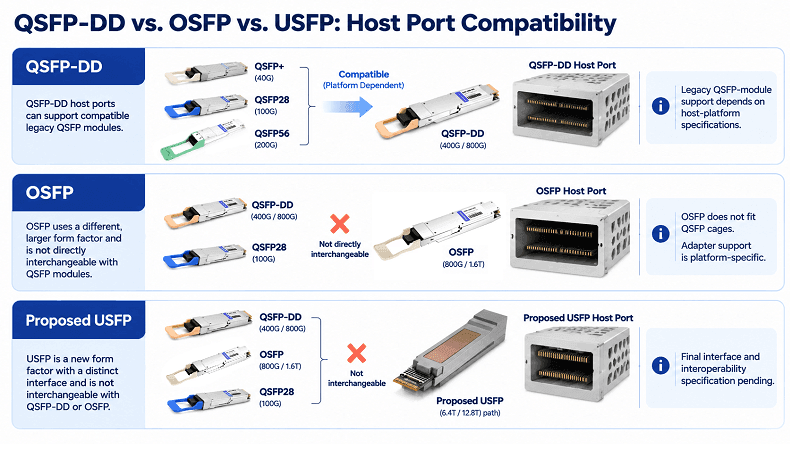
OSFP’s Heatsink and Thermal Options
Standard OSFP modules include an integrated heatsink, and the OSFP ecosystem supports higher-power module generations. This can make OSFP attractive for systems using high-power optics or operating under demanding thermal conditions. However, QSFP-DD also has higher-power variants and enhanced thermal designs; it is not accurate to say that QSFP-DD cannot support high-power modules.
For AI clusters, coherent optics, and other demanding applications, compare the exact module’s power consumption, the switch’s port-level power limit, heatsink design, airflow, ambient temperature, and system qualification. OSFP’s larger form factor can provide useful thermal design options, but the host platform determines the final result.
USFP’s 100 W Envelope and Two-Step Connector
USFP’s announced design targets power dissipation of up to 100 W and uses a two-dimensional connector array with a two-step insertion mechanism. The design is intended to improve signal integrity and reduce wear on high-speed contacts. The 100 W capability does not mean that a transceiver can operate without cooling; it means the design does not require a separate, dedicated cooling circuit inside the transceiver.
A 100 W module presents a substantial system-level thermal challenge. Liquid cooling may be appropriate in some dense deployments, but it should not be described as universally required without a specific host-system design. Despite its OSFP-sized footprint, USFP is a distinct proposed design and should not be assumed to fit existing OSFP or QSFP-DD cages.
OSFP vs. QSFP-DD: The 400G and 800G Decision
Until USFP’s specification and ecosystem mature, most immediate decisions will involve available QSFP-DD and OSFP platforms.
When QSFP-DD Wins
Choose QSFP-DD when the target switch platform uses QSFP-DD cages and you want to retain compatible QSFP-family modules where the host supports them. It is widely used in enterprise and data-center Ethernet platforms, and the ecosystem supports multiple generations of 400G, 800G, and specified 1.6T modules.
QSFP-DD may also be a cost-effective option for short-reach data-center links because of its broad supplier ecosystem. Compare the total cost of the switch, transceivers, cabling, power, and cooling rather than assuming that the form factor alone determines cost.
When OSFP Wins
Choose OSFP when the selected switch platform uses OSFP cages or when its thermal design and supported power envelope better match the target modules. OSFP may be suitable for some 800G coherent optics, AI clusters, and InfiniBand or Ethernet systems, but the exact module and host platform must be checked.
The trade-off is mechanical compatibility: OSFP modules do not fit directly into QSFP cages. Selected host platforms may support legacy QSFP modules through adapters, but this is not universal. The cage type and vendor’s compatibility matrix should be confirmed before the system is selected.
Why USFP Matters: The 1.6T and AI-Fabric Roadmap
USFP is not yet a generally available product based on the October 2026 announcement, but it signals one possible direction for higher-density AI networking.
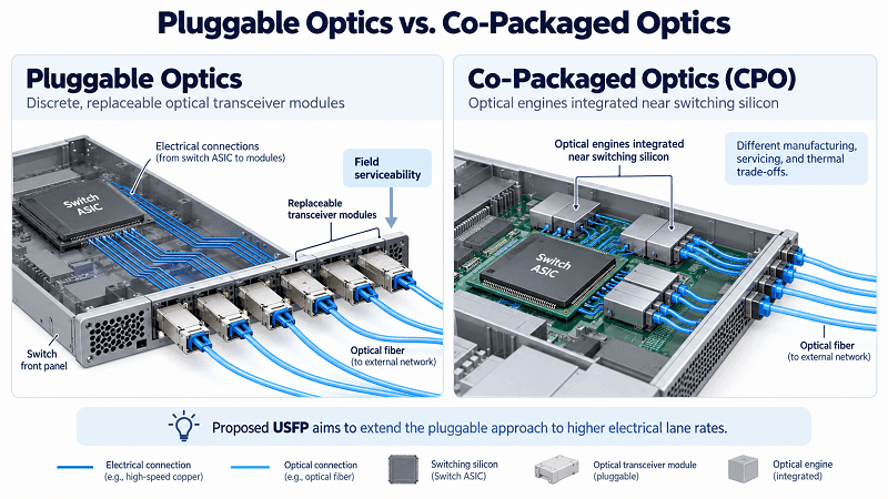
Pluggable Optics vs. Co-Packaged Optics
The optical industry continues to develop both pluggable modules and co-packaged optics (CPO). CPO places optical engines close to, or within the same package as, switching silicon and may improve power efficiency and density. It also changes how systems are manufactured, serviced, and upgraded. The trade-offs depend on the implementation.
USFP is intended to extend the pluggable model to higher electrical lane rates while retaining the serviceability and field-replaceability of pluggable transceivers. It could be an option for systems that need greater bandwidth density without moving directly to CPO, but its eventual value will depend on the final specification, system integration, interoperability, and real-world product performance.
USFP Ecosystem Status
NVIDIA and Cisco have announced plans to develop an open industry specification through an upcoming community-led multi-source project. They are working with TE Connectivity and Amphenol on cages, connectors, and modules, with additional partners expected to join.
As of the announcement, the final public specification and a public sampling or general-availability timeline had not been specified. Network planners should treat USFP as a roadmap item and confirm the latest official updates before using it as a procurement assumption.
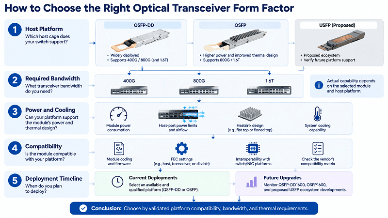
How to Choose the Right Form Factor
Use this checklist to move from comparison to decision.
- Check your existing infrastructure. If you use QSFP28 or QSFP56 modules today, a QSFP-DD host port may support compatible modules during a phased migration. Confirm the switch vendor’s compatibility list.
- Estimate your power and thermal budget. For high-power optics or demanding AI workloads, compare the module’s maximum power, host-port limits, heatsink, airflow, and any system-level cooling requirements. Do not choose by form factor alone.
- Confirm your switch roadmap. The host cage, supported electrical interface, firmware, and validated module list determine which transceivers you can use.
- Look at the five-year horizon. If you are planning for 1.6T and higher-density AI fabrics, track QSFP-DD1600, OSFP1600, and USFP developments. Verify the availability of compatible switch silicon and validated systems before committing.
- Avoid premature lock-in. For most deployments, choosing an available, qualified QSFP-DD or OSFP platform and monitoring USFP’s specification and ecosystem progress is safer than basing a current deployment on an unfinalized form factor.
FiberMall’s Guidance and Product Support
FiberMall offers 400G and 800G optical transceivers across QSFP-DD and OSFP form factors, including modules intended for use with platforms from vendors such as Cisco, Juniper, Arista, and NVIDIA. Compatibility should be confirmed for the exact part number, host platform, module coding, firmware, FEC settings, and power and thermal requirements.
Explore FiberMall’s 400G and 800G optical transceivers to review the available portfolio and identify the appropriate module for your network.
Conclusion
The USFP vs. OSFP vs. QSFP-DD decision depends on the target bandwidth, host platform, thermal design, compatibility requirements, and deployment timeline. QSFP-DD offers broad backward compatibility with supported QSFP-family modules and a path through 400G, 800G, and specified 1.6T generations. OSFP provides a different mechanical and thermal design, including support for higher-power module generations. USFP is a proposed 400G-per-lane pluggable form factor that could support higher-density AI fabrics, but its final specification, compatible silicon, and product availability remain under development.
The practical takeaway is to choose QSFP-DD or OSFP based on the qualified host platform and actual module requirements, while tracking USFP through its specification and ecosystem development before making a procurement commitment.