Preface
In communications engineering, the commonly used fiber optic connector interface types for SC, FC, and LC type, which are single-core connectors, each pair of connectors can only complete a fiber optic connection. In the data center, it is also common to use multi-core connectors, each pair of connectors to complete the activities of 2 to 32-core connection, this connector is the MPO (Multi-fiber Push On) type fiber optic connector (hereinafter referred to as “MPO connectors”).
Introduction to MPO Connectors
MPO connector is a multi-core pluggable connector, that consists of a female plug, male plug, and adapter, as shown in Figure 1. The male plug has 2 guide pins and the female plug has 2 guide pin holes. The connector is aligned by the guide pins and guide pin holes and locked by the adapter.
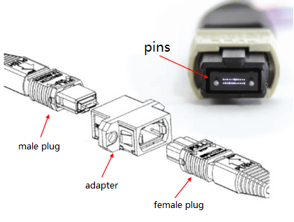
Figure 1. MPO Connector Structure
MPO connectors are commonly used 8, 12, 16, and 24-core, the current maximum number of cores for 32, different cores of the connector shape and size are basically the same. MPO connector size than the commonly used SC connector is slightly larger, Figure 2 for the external dimensions of the MPO and SC connector plug.
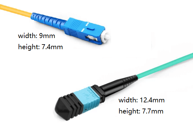
Figure 2. The Size of the MPO Connector
MPO connector insertion loss is usually larger than the single-core connector, with multimode MPO connector insertion loss typical value of about 0.25dB, and the insertion loss of conventional single-mode MPO connector has a typical value of about 0.6dB, as shown in Figure 3 (the vertical coordinate in the figure is the number of samples). Because of the difficulty of accurately aligning multiple cores at the same time, the difference in insertion loss for different cores of the same connector is often large.
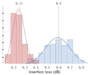
Figure 3. The insertion loss of the MPO connector
FiberMall can also provide low insertion loss single-mode MPO connectors, with a maximum insertion loss of not more than 0.35 dB. Figure 4 shows the distribution of insertion loss of some low-loss single-mode MPO connectors of a domestic connector head enterprise.
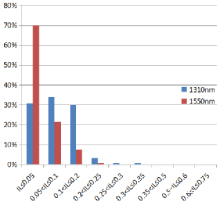
Figure 4. The insertion loss of low insertion loss MPO
Application of MPO Connector
Data center cabling systems commonly use MPO connectors. The basic structure of the data center cabling system based on the leaf-ridge architecture is shown in Figure 5. Since the high-speed optical modules of the network equipment (servers and matrix switches in Figure 5) generally use MPO interfaces, the corresponding equipment patch cords, horizontal cables, and distribution frames are required to support MPO connections.
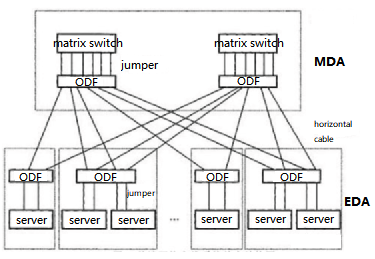
Figure 5. The basic structure of the data center cabling system
The fiber optic link between the server and the matrix switch is shown in Figure 6.
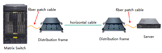
Figure 6. Fiber optic link between network devices
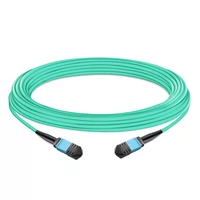
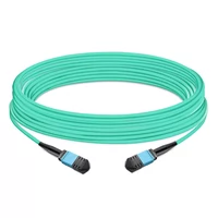
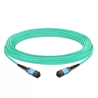
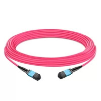
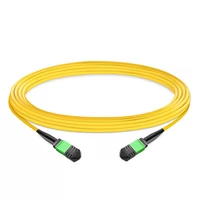
Horizontal cables, also known as MPO trunk cables, are usually MPO patch fibers. MPO patch fibers are multi-core fiber optic cable assemblies with MPO plugs pre-fabricated at both ends, as shown in Figure 7. The commonly used MPO patch fiber cores are 8, 12, 16, and 24 cores, and the outer diameter of the fiber optic cable of the patch fiber is about 3.0 mm.
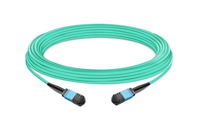
Figure 7. MPO Trunk Cable
According to the different types of fiber optic interfaces on the panel, the distribution frame is divided into an MPO interface unit and an LC interface unit. the MPO interface unit is shown in Figure 8, the unit panel is usually installed with multiple sets of adapter panel strips, multiple MPO adapters are installed on each panel strip, and the MPO plugs of the horizontal cables are directly inserted into the inner side of the MPO adapters.
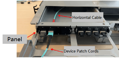
Figure 8. ODF unit in MPO interface
The LC interface unit, as shown in Figure 9, generally includes multiple MPO-LC conversion modules internally, each of which can convert 1 to 3 cores of MPO horizontal cable into multiple LC fiber interfaces. For example, one 12-core MPO patch fiber is converted into 12 LC fiber interfaces.
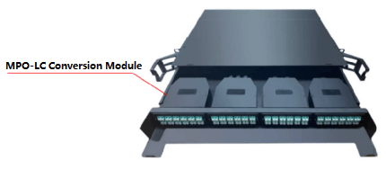
Figure 9. ODF unit in LC interface
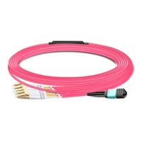
When the interface of the network device is MPO, the device patch cable adopts the MPO patch fiber shown in Figure 7. When the interface of the network device is LC, if it is connected to the LC port of the distribution frame, the device patch cord adopts LC-LC patch fiber; if it is connected to the MPO port of the distribution frame, the device patch cord adopts MPO-LC breakout cable. As shown in Figure 10.
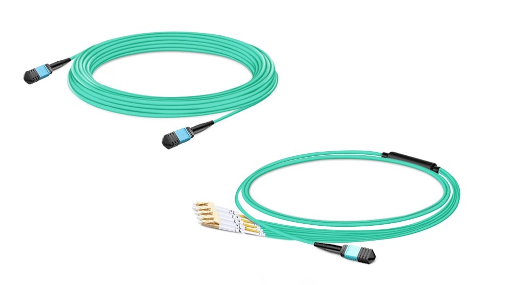
Figure 10. Fiber jumpers for LC interfaces
MPO Connector Application in Communication Network
The use of MPO connectors in data centers is on the one hand due to the connection needs of MPO optical modules for data equipment. On the other hand, compared to single-core connections, MPO’s high-density connections can make the server room cabling neater and the cabling system occupies less space in the server room. Figure 11 shows the partial of a data center.
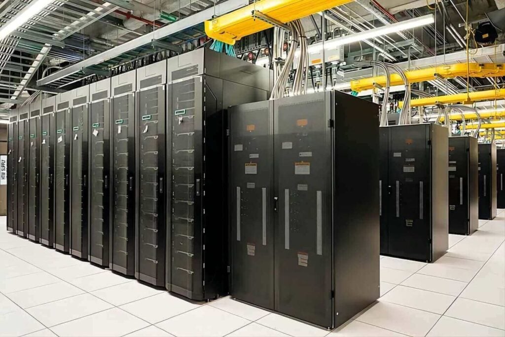
Figure 11. Data center
The patch cords in the communication room are generally single-core patch cords with a diameter of 2.0mm. When the number of fiber links per unit area is similar, the fiber cabling in the communication room is much more chaotic. Figure 12 shows the current situation of patch cord placement in a communication room. When laying the same length on the same path, the workload of one multi-core MPO patch cord and one single-core patch cord is basically the same, and the cost of laying so many patch cords is also astonishing.
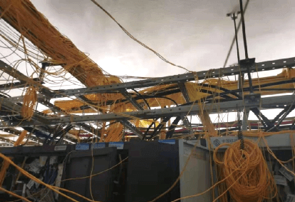
Figure 12. Status of Patch Fiber Placement in Some Communication Rooms
The optical modules of communication equipment are usually LC interfaces. Although there is no MPO connection requirement for optical channels between devices, MPO connection can significantly improve the cabling density in scenarios where there are a large number of single-core patch cords on the same path. There is a kind of MPO interface ODF fusion splicing integrated tray with a capacity of 48 cores, with 8 MPO interfaces, each MPO interface has 6 cores, as shown in Figure 13. Using this tray in ordinary optical cable junction boxes or ODF can increase the capacity density of junction boxes or ODF by 4 times and reduce the number of patch cords by 1/3.
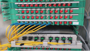
Figure 13. Using MPO connections in OCC
Theoretically, if there are a large number of patch cords interconnecting devices between rack columns M and N in the communication room, then it is suitable to use MPO components to connect between columns M and N; in optical cable lines or ODNs, if A, B, and C are ODF units (ODF or OCC) at different locations, and there are a large number of cores that need to be transferred through B between A and C, then the ODF unit at point B should use MPO components to connect, such as the trunk OCC in ODN.
Conclusion
For a long time, single-core connections have been used for active connections of optical fibers in communication networks, but with the development of communication services, the explosive growth of active connections has also made the disadvantages of single-core connections more obvious. Low-density ODFs occupy a lot of room space, and many single-core patch cords far exceed the capacity limit of the wiring racks in the room; the number and volume of roadside OCC are increasing.
Although using high-density connections based on MPO in communication networks can improve the above situation, single-mode fibers are used in communication networks. The price of single-mode MPO connectors is higher than that of multimode MPO connectors. The insertion loss is also greater than that of multimode MPO connectors and single-mode single-core connectors. This also has some impact on the application of MPO connectors in communication networks.
Related Products:
-
 NVIDIA MFP7E10-N010 Compatible 10m (33ft) 8 Fibers Low Insertion Loss Female to Female MPO Trunk Cable Polarity B APC to APC LSZH Multimode OM3 50/125
$47.00
NVIDIA MFP7E10-N010 Compatible 10m (33ft) 8 Fibers Low Insertion Loss Female to Female MPO Trunk Cable Polarity B APC to APC LSZH Multimode OM3 50/125
$47.00
-
NVIDIA MFP7E10-N030 Compatible 30m (98ft) 8 Fibers Low Insertion Loss Female to Female MPO Trunk Cable Polarity B APC to APC LSZH Multimode OM3 50/125
$81.00
-
5m (16ft) 12 Fibers Female to Female MPO Trunk Cable Polarity B LSZH OM3 50/125 Multimode Fiber
$26.00
-
7m (23ft) 12 Fibers Female to Female MPO Trunk Cable Polarity B LSZH Multimode OM4 50/125
$35.00
-
10m (33ft) 12 Fibers Female to Female MPO Trunk Cable Polarity B LSZH OS2 9/125 Single Mode
$32.00
-
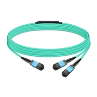
NVIDIA MFP7E20-N010 Compatible 10m (33ft) 8 Fibers Low Insertion Loss Female to Female MPO12 to 2xMPO12 Polarity B APC to APC LSZH Multimode OM3 50/125
$61.00
-
5m (16ft) MPO UPC Female to 4 LC UPC Duplex OM4 50/125 Multimode Fiber Breakout Cable, 8 Fibers Type B, LSZH, Aqua/Violet
$32.00
-
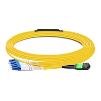
7m (23ft) MPO APC Female to 4 LC UPC Duplex OS2 9/125 Single Mode Fiber Breakout Cable, 8 Fibers Type B, LSZH, Yellow
$28.00