Overview of Fiber Bend
Fiber optic sensors are small in size and can be bent. They can be installed in samples in small spaces. A too small bending radius will cause optical signal loss and affect the accuracy of sensing measurements. However, in many practical application scenarios, optical fiber sensors inevitably have a small bending radius during their installation. How to solve the loss caused by optical fiber bend has become people’s focus. Let’s take a look at the adverse effects of ordinary optical fiber bend and the working principle of the small bending radius of bend-resistant optical fiber.
Why Shouldn’t Optical Fibers be Bent Excessively?
When light travels from one medium to another, it is refracted and reflected at the interface between the two media. As the incident angle increases, the reflected light becomes stronger, and the refracted light becomes weaker. When the incident angle is large enough, the refracted light disappears completely, leaving only reflected light. This phenomenon is called total reflection.
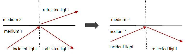
Total reflection phenomenon
Optical fiber consists of a three-layer structure of core, cladding and coating. The refractive index of the core is greater than the refractive index of the cladding. Light can achieve total reflection transmission in the core.
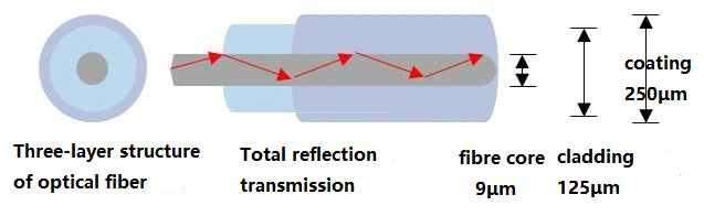
Total reflection in optical fibers
Generally, the loss coefficient of standard single mode optical fiber at the wavelength of 1550nm is about 0.2dB/km, which is a low transmission loss. If the optical fiber is bent (macro-bending or micro-bending), the light transmission does not meet the total reflection condition, and part of the light leaks out of the cladding, resulting in a decrease in optical power and loss.
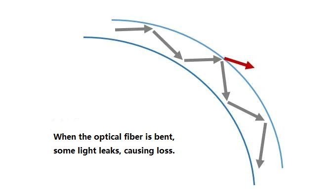
The bending state of optical fibers
How to Reduce Bending Loss
The main cause of loss in optical fiber links is that there are large-angle bends in local locations of optical fibers during their installation and layout,which are common in optical fiber joints and turns.This type of bending loss is reversible. Increasing the bending radius of the optical fiber will greatly improve the link loss. What is the transmission path of light in optical fiber?
lf we use OFDR equipment to measure optical fiber links, we will obtain an OFDR distribution curve (distance intensity/reflectivity). The curve can reflect the loss at each position in the optical fiber link. The loss is mainly presented in the form of steps, as shown in the figure below. Users can use the OFDR curve to analyze and find the bending position and make adjustments.
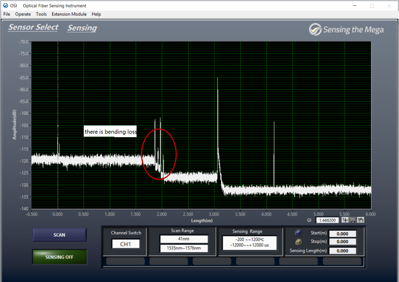
OFDR curve when optical fiber is bent
Users can also choose bend-insensitive (bend-resistant) optical fibers as sensors, which can reduce the impact of bending losses. Bending-resistant optical fiber can tolerate a smaller bending radius. For example, the minimum bending radius of single mode high-temperature strain-resistant optical fiber (model: Pl125) is about 5mm.The minimum bending radius of tight sheath strain sensing optical cable (model: SS-0.9mm) is about 8mm.
Introduction to Bend-resistant Optical Fibers
It is recommended that the bending radius of conventional single mode optical fiber (G.652 type) be greater than 5mm (diameter 1cm), otherwise the optical signal will be significantly lost, resulting in a decrease in the signal-to-noise ratio of the sensing measurement and unstable measurement results. Regarding the minimum bend radius, the rule of thumb is: for long-term applications, the bend radius should exceed 150 times the fiber cladding diameter; for short-term applications, the radius should exceed 100 times the cladding diameter. The cladding diameter of conventional single mode optical fiber is 125 μm, and the minimum bending radii of the above two types are 19 mm and 13 mm respectively.
Bending-resistant optical fiber (G.657 type) mainly improves the bending resistance by changing the structural design of the optical fiber. There is a common index in the industry for evaluating bending sensitivity: MAC value.
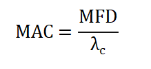
MAC Formula
The MAC value is the ratio of the mode field diameter and the cut-off wavelength in a near-step index waveguide fiber. The lower the MAC value, the less sensitive the fiber is to bend. Some basic approaches to designing bend-insensitive fibers include reducing the mode field diameter, or increasing the cutoff wavelength, or doing both. Specific methods include:
(1) Reduce the mode field diameter to improve light control. Such as reducing the core diameter or increasing the core refractive index.
(2) Reduce the fiber cladding diameter to increase bending resistance. The diameter of existing bend-resistant optical fibers will be reduced from 125 microns to 80 microns, and even an outer diameter of 60 microns has appeared.
(3) Add a cladding layer of low refractive index trenches. The function is similar to increasing the refractive index of the fiber core.
All of the above methods can better control the transmission of light beams in the fiber core,thereby reducing the impact of fiber bending in sensing measurements. The commonly used type of bend-resistant optical fiber on the market is G.657B3. The bending radius and bending loss parameters are shown in the table below.
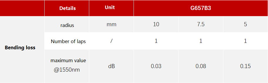
Parameters of Bend-resistant fibers
Related Products:
-
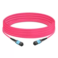
 NVIDIA MFP7E10-N035 Compatible 35m (115ft) 8 Fibers Low Insertion Loss Female to Female MPO Trunk Cable Polarity B APC to APC LSZH Multimode OM4 50/125
$118.00
NVIDIA MFP7E10-N035 Compatible 35m (115ft) 8 Fibers Low Insertion Loss Female to Female MPO Trunk Cable Polarity B APC to APC LSZH Multimode OM4 50/125
$118.00
-
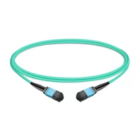
NVIDIA MFP7E10-N003 Compatible 3m (10ft) 8 Fibers Low Insertion Loss Female to Female MPO Trunk Cable Polarity B APC to APC LSZH Multimode OM3 50/125
$35.00
-
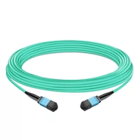
5m (16ft) 16 Fibers Female to Female MPO Trunk Cable Polarity B LSZH OM4 50/125 Multimode Fiber APC
$89.00
-
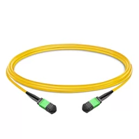
1m (3ft) 12 Fibers Low Insertion Loss Female to Female MPO Trunk Cable Polarity B LSZH OS2 9/125 Single Mode
$40.00
-
1m (3ft) 12 Fibers Low Insertion Loss Female to Female MPO Trunk Cable Polarity B LSZH Multimode OM4 50/125
$33.00
-
1m (3ft) 24 Fibers Female to Female Elite MTP Trunk Cable Polarity A Plenum (OFNP) OS2 9/125 Single Mode for 100G CPAK LR Connectivity
$105.00
-
1m (3ft) 24 Fibers Female to Female Elite MTP Trunk Cable Polarity A Plenum (OFNP) Multimode OM4 50/125 for 100GBASE-SR10 Connectivity
$63.00
-
1m (3ft) 12 Fibers Female to Female Elite MTP Trunk Cable Polarity B Plenum (OFNP) OS2 9/125 Single Mode
$42.00
-
1m (3ft) 12 Fibers Female to Female Elite MTP Trunk Cable Polarity B Plenum (OFNP) Multimode OM4 50/125
$37.00
-
1m (3ft) 12 Fibers Female to Female Elite MTP Trunk Cable Polarity B Plenum (OFNP) OM3 50/125 Multimode Fiber
$36.00
-
1m (3ft) Duplex OM3 Multimode SC UPC to SC UPC OFNP Fiber Optic Cable
$3.00
-
1m (3ft) Duplex OM3 Multimode LC UPC to SC UPC OFNP Fiber Optic Cable
$3.00
-
1m (3ft) Duplex OM3 Multimode LC UPC to LC UPC OFNP Fiber Optic Cable
$3.00
-
1m (3ft) Duplex OM3 Multimode SC UPC to SC UPC LSZH Fiber Optic Cable
$3.00
-
1m (3ft) Duplex OM3 Multimode LC UPC to SC UPC LSZH Fiber Optic Cable
$3.00
-
1m (3ft) Duplex OM4 Multimode SC UPC to SC UPC OFNP Fiber Optic Cable
$3.10
-
1m (3ft) Duplex OM4 Multimode LC UPC to SC UPC OFNP Fiber Optic Cable
$3.10
-
1m (3ft) Duplex OM4 Multimode LC UPC to LC UPC OFNP Fiber Optic Cable
$3.10
-
1m (3ft) Duplex OM4 Multimode SC UPC to SC UPC LSZH Fiber Optic Cable
$3.10
-
1m (3ft) Duplex OM4 Multimode LC UPC to SC UPC LSZH Fiber Optic Cable
$3.10