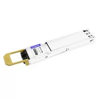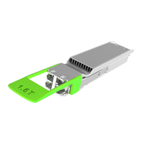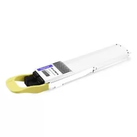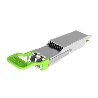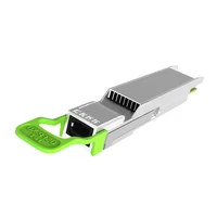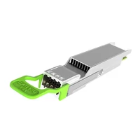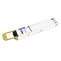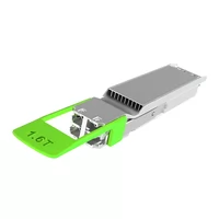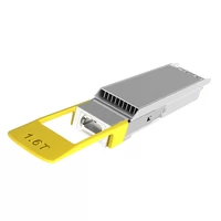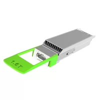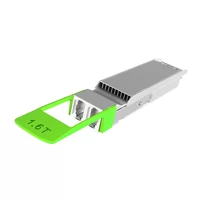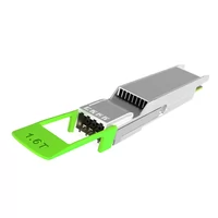

1.6T optical transceivers are emerging as the next step in high-speed connectivity for AI data centers, while 3.2T remains an early-stage technology direction. For hyperscale computing clusters, these architectures can increase bandwidth per port and support continued network scaling. Actual latency and energy-efficiency benefits depend on the transceiver design, host platform, link configuration, and cooling system.
What Is a 1.6T Optical Transceiver?
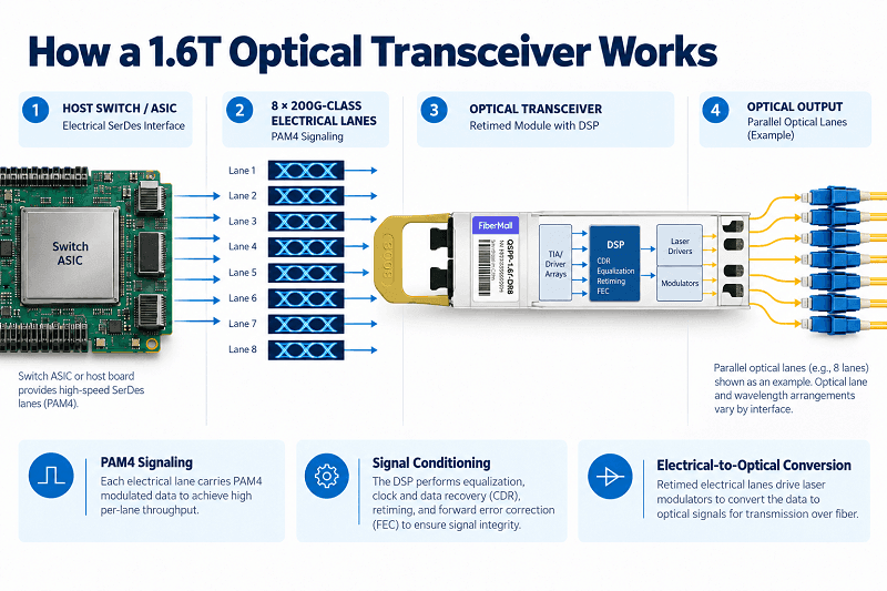
A 1.6T optical transceiver is a hot-pluggable module that converts electrical signals from a switch or network interface card (NIC) into optical signals, and converts received optical signals back into electrical signals. It supports an aggregate data rate of 1.6 Tb/s and represents the next step beyond 800G connectivity. Many 1.6T single-mode designs use eight 200G optical lanes, although the exact lane and wavelength arrangement depends on the optical interface.
The 8 × 200G PAM4 Architecture
A common 1.6T architecture uses eight lanes, each carrying approximately 200 Gb/s of payload data with PAM4 modulation. PAM4 encodes two bits per symbol by using four amplitude levels rather than two. This increases the data rate per lane without requiring a proportional increase in symbol rate.
In practice, a 200G-per-lane implementation commonly operates at approximately 106.25 GBd using 224G-class electrical signaling. The 224G-class label describes the signaling generation; it should not be interpreted as 224 Gb/s of net Ethernet payload per lane. The host electrical interface uses eight high-speed lanes, with the exact interface name and compliance requirements determined by the applicable Ethernet specification and platform implementation—not by the OSFP MSA alone. In a retimed module, the DSP typically performs signal equalization, clock and data recovery, and gearbox functions. FEC processing may be performed in the host PHY, the module, or across the link architecture, depending on the implementation.
224G SerDes, DSP, and FEC
At 1.6T, signal integrity is a major engineering constraint. At a symbol rate of about 106.25 GBd, the Nyquist frequency is approximately 53 GHz. PCB insertion loss generally increases with frequency and channel length; some channel examples may show loss rising from around 10 dB for 100G-per-lane signaling to 16–20 dB for 200G-per-lane signaling. These figures are illustrative rather than universal, because actual loss depends on the PCB stack-up, trace length, connectors, and measurement conditions. This challenge is one reason the industry is evaluating linear optics and co-packaged optics.
PAM4 provides more bits per symbol than NRZ signaling, but its smaller eye openings leave less noise margin. Forward error correction (FEC) helps maintain link reliability. Depending on the Ethernet PHY and link architecture, FEC may use inner and outer coding stages, and it should not be assumed that all FEC processing takes place inside the module DSP. DSPs and SerDes for these systems use advanced CMOS processes; the specific process node depends on the chip. Vendors in this ecosystem include Marvell and Cisco’s Acacia business, among others.
Form Factors: OSFP1600, OSFP-XD, and QSFP-DD
The standard OSFP form factor has eight high-speed electrical lanes and can support 1.6T when each lane operates at 200G class. OSFP-XD is a separate form factor with sixteen high-speed electrical lanes, providing a path to 3.2T using sixteen 200G-class lanes. OSFP and OSFP-XD have different mechanical and electrical interfaces and are not interchangeable. QSFP-DD-based 1.6T ecosystem support varies by vendor and platform, so verify the host port, module specification, thermal design, and qualification status before selecting a form factor. OSFP is common among announced 1.6T offerings, but actual deployment choices depend on platform availability and compatibility.
1.6T Optical Module Variants: DR8, 2×FR4, and More
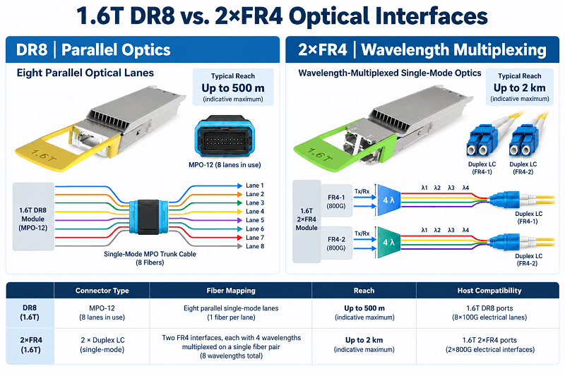
Not all 1.6T optical transceivers are the same. The required reach, available cabling, host compatibility, and power budget determine which variant is suitable. The figures below are indicative examples, not universal specifications; always check the exact product datasheet.
| Variant | Typical Reach | Optical Connectors | Indicative Module Power | Typical Use |
| DR8 (retimed) | Up to 500 m | Dual MPO-12 or MPO-16 APC, depending on design | About 22–32 W | Parallel single-mode fabric links |
| 2×FR4 | Up to 2 km | Dual duplex LC | About 26–30 W | Longer-reach single-mode links |
| DR8 LPO | Up to 500 m | MPO-16 or dual MPO-12, depending on design | Around 10 W in some designs | Power-constrained AI clusters |
| DR8 LRO | Up to 500 m | MPO-16 or dual MPO-12, depending on design | About 16–20 W in some designs | A compromise between power and signal conditioning |
| SR8 | Typically up to 100 m | MPO-16 multimode | Varies by product | Short-reach multimode links |
| SR16 | Typically up to 100 m | Higher-count multi-fiber interface; verify the product specification | Varies by product | Short-reach multimode links |
DR8 Parallel Optics
DR8 uses eight parallel single-mode optical lanes and commonly supports reaches of up to 500 m. It is a candidate for AI cluster spine-and-leaf links. A key cabling consideration is that some DR8 modules use MPO-16, while others use dual MPO-12 connectors; many existing 800G DR4 deployments use MPO-12. A dual-MPO-12 DR8 module may reuse existing 800G DR4 trunk cabling if the connector mapping, polarity, fiber type, and insertion-loss budget are compatible. Check the module datasheet and cabling design before assuming direct reuse.
2×FR4 Wavelength-Multiplexed Optics
A 2×FR4 module combines two 800G FR4 optical interfaces in one module, using wavelength multiplexing to carry the signals over single-mode fiber. It can support reaches of up to 2 km through two duplex LC interfaces. For links longer than 500 m and within the supported 2 km reach, 2×FR4 may be an option. Confirm the exact reach, wavelength plan, and host compatibility for the selected product.
1.6T vs. 800G: When to Upgrade (and When to Wait)
The answer to “Should I move to 1.6T?” depends on bandwidth demand, platform readiness, interoperability, and power and cooling capacity. In many environments, staying with 800G remains reasonable until these requirements justify a migration.
What Changes: Lanes, Standards, Power, and Cooling
A 1.6T optical transceiver doubles the aggregate capacity of an 800G module, but it also raises signal-integrity and thermal requirements. Common 800G implementations use eight 100G lanes. IEEE 802.3ck defines relevant 100G-per-lane electrical signaling technology, while IEEE 802.3df-2024 specifies 400G and 800G Ethernet. The next-generation 1.6T Ethernet work is covered by IEEE P802.3dj, which was in late-stage approval as of October 2026; check the latest IEEE status before describing it as a finalized, published standard.
Typical 800G module power may be around 14–16 W, depending on the design. Fully retimed 1.6T modules commonly require more power, with announced examples in the mid-20 W range and some designs exceeding 30 W. A platform may allocate a higher power budget per port, potentially approaching 40 W in some configurations, but that should not be treated as a universal module rating. Verify the maximum power and thermal requirements in the relevant datasheets.
Cooling is an important design consideration, but liquid cooling is not a universal requirement for every 1.6T deployment. Some qualified platforms may support 1.6T modules with air cooling, while high-power, high-density configurations may require stronger airflow or liquid cooling. Thermal feasibility depends on total switch power, port density, chassis design, airflow, ambient temperature, and the module’s cooling requirements.
What Carries Forward: Fiber Plant and MPO-12 Trunks
Existing OS2 single-mode fiber, MPO-12 trunks, and duplex-LC cabling may be reusable during a migration. However, reuse is not guaranteed simply because the fiber type is unchanged. Connector mapping, polarity, fiber count, insertion loss, optical interface, and required reach must all be checked. Some links may need new patch cords, breakout harnesses, or other cabling changes. A phased migration—starting with the spine and expanding toward the leaf layer—can help reduce disruption when the host platforms and optical interfaces support the planned topology.
A Phased Migration and Breakout Strategy
Some 1.6T ports and modules can support breakout into 2 × 800G or 4 × 400G, provided that the switch ASIC, module configuration, port mapping, firmware, and network operating system support the required modes. This can provide a migration path between 1.6T-capable spine ports and existing 800G links, but compatibility must be verified for the exact platform and module combination.
Consider upgrading when your vendor offers qualified 1.6T platforms with confirmed availability, validated interoperability, and sufficient power and thermal headroom. If those conditions are not met, staying with 800G may be the more practical choice.
3.2T Optical Transceivers: The Next Step
A 3.2T optical transceiver aims to double the aggregate bandwidth of 1.6T. One approach uses sixteen 200G-class lanes; other architectures may use a different lane arrangement, such as thirty-two 100G lanes. The term “224G-class” refers to the electrical signaling generation and should not be confused with 224 Gb/s of net payload per lane. Although 3.2T is important to future network planning, its commercial timing and deployment scale remain dependent on product, platform, and ecosystem readiness.
What Is 3.2T?
The aggregate data-rate calculation is 16 × 200 Gb/s = 3.2 Tb/s. In a 200G-per-lane implementation, the electrical interface uses 224G-class signaling to support the target lane data rate. The main challenges extend beyond the optical engine: as speeds increase, the electrical distance between the switch ASIC and optical engine can have a greater impact on power consumption and signal integrity. This is one reason packaging options are receiving significant attention.
The Packaging Options: LPO/LRO, NPO, and CPO
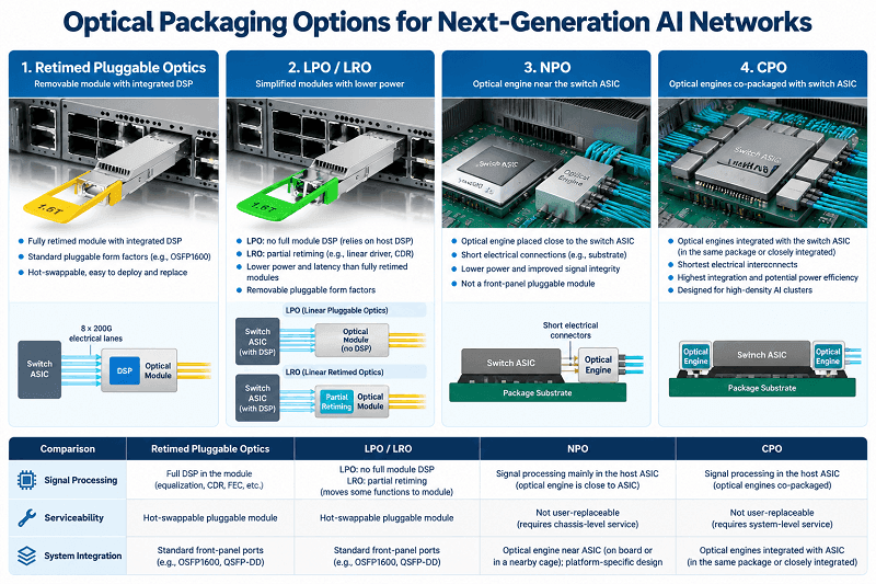
An important long-term decision is how close the optical engine sits to the switch chip. The main options differ in signal processing, power consumption, serviceability, and integration complexity:
- Pluggable optics (retimed): Often cited at around 15 pJ/bit in some comparisons; field-replaceable and based on a mature deployment model.
- LPO/LRO: Some designs are cited at around 10 pJ/bit. LPO removes the full module DSP, while common LRO implementations retain transmit-side retiming and use a linear receive path.
- NPO (near-packaged optics): Some estimates fall around 8–10 pJ/bit, with the optical engine positioned close to the host ASIC to improve density.
- CPO (co-packaged optics): Some estimates are around 6 pJ/bit, potentially offering high energy efficiency but increasing system integration and serviceability complexity.
These pJ/bit figures are illustrative estimates, not universal category values. They should not be compared directly unless the measurement boundaries are consistent—for example, whether the figures include the host ASIC, DSP, laser source, and cooling overhead.
The future balance between pluggable modules, NPO, and CPO is not settled. Pluggables offer field replaceability and sourcing flexibility, while NPO and CPO may be attractive for systems with demanding bandwidth-density and power requirements. Public reports have described 3.2T NPO demonstrations and pilot activity, including work associated with Alibaba, but a demonstration or pilot should not be equated with volume production. Check current official announcements before making claims about a specific solution’s production status. For the pluggable-versus-co-packaged decision, our USFP vs. CPO comparison goes deeper.
Silicon Photonics and the Path to Commercialization
Silicon photonics is a promising approach for high-bandwidth optical engines because it can integrate optical functions into a compact platform. It is not, however, the only possible architecture for 3.2T. Depending on the design, integrating multiple lasers and modulators using discrete components can increase cost, power consumption, and packaging complexity.
Heterogeneous integration is another approach. For example, OpenLight’s technology combines indium phosphide (InP) gain material with a silicon photonics platform. The commercial timeline for 3.2T remains uncertain. As of October 2026, it is more accurate to describe 3.2T as an emerging technology with development and demonstration activity than to promise a specific mass-production date. Commercial scaling in 2027 or later may be a planning scenario for some vendors, not a guaranteed industry-wide schedule.
Power, Cooling, and the Packaging Decision
The headline data rate is only one part of the decision. Power consumption, thermal design, host compatibility, and serviceability can have a greater effect on total deployment cost and operations.
Retimed vs. LPO vs. LRO
A retimed 1.6T optical transceiver typically uses a DSP to process both transmit and receive paths. This can improve signal conditioning and help support interoperability across qualified platforms, but it generally increases module power. Many announced designs fall in the mid-20 W range, while exact maximum power varies by product.
LPO stands for linear pluggable optics. It removes the full module DSP and relies more heavily on the host SerDes and the module’s linear analog components for signal conditioning. Some implementations target power around or below 10 W and can reduce latency, but the actual benefit depends on the design. LPO also places greater demands on host compatibility, channel design, and system validation.
LRO commonly retains transmit-side retiming while using a linear receive path, although implementations vary. Announced designs often fall in the 16–20 W range. Treat these figures as examples, not guaranteed values for every LRO product.
Air vs. Liquid Cooling
Whether 1.6T requires liquid cooling depends on module power, port density, chassis design, airflow, ambient conditions, and the host platform’s thermal limits. Higher-density 3.2T systems may place even greater demands on thermal management, but liquid cooling should not be presented as an unavoidable requirement for every design. If liquid cooling is not planned, evaluate whether the intended module and switch configuration can meet its thermal requirements with a qualified air-cooling solution.
Pluggable vs. NPO vs. CPO
The strategic choice is between field-replaceable optics and more integrated optical architectures. Pluggable modules can support multi-vendor sourcing and straightforward replacement when the products are qualified for interoperability. CPO can improve bandwidth density and energy efficiency, but optical-engine maintenance may be more complex than replacing a pluggable module; some designs use external laser sources that can be serviced separately. NPO places the optical engine closer to the host ASIC, but its serviceability and sourcing flexibility depend on the specific system architecture.
How to Choose a 1.6T / 3.2T Path
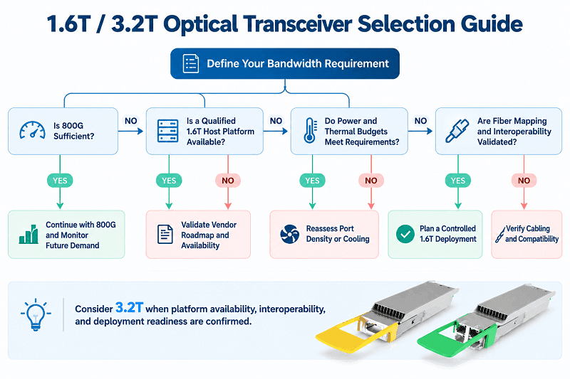
The right choice depends on your deployment constraints. Work through these five factors before standardizing on a speed or packaging architecture.
- Bandwidth requirements: Do you need 1.6 Tb/s per port now, or would 800G with more ports meet the requirement?
- Power and cooling budget: Can the platform support the module’s maximum power at the planned port density, with adequate thermal headroom?
- Fiber plant: Is the cabling MPO-16, MPO-12, or duplex LC, and are the connector mapping, polarity, and loss budget compatible with the selected PMD?
- Vendor and packaging flexibility: Do you need field-replaceable pluggables and multi-vendor sourcing, or can you support an NPO/CPO architecture?
- Availability and operational readiness: Are the modules and host platforms available, qualified for interoperability, and supported by a clear deployment and maintenance plan?
For many enterprise and multi-tenant operators in 2026, 800G may remain the practical choice until bandwidth demand, product availability, and platform readiness justify 1.6T. Planning for future cooling needs is sensible, but liquid cooling should not be treated as a universal prerequisite for 1.6T. Hyperscale AI clusters with qualified 1.6T-capable platforms, sufficient power and thermal headroom, and a validated network design may be able to deploy 1.6T today. A 3.2T migration should remain tied to vendor roadmaps, interoperability testing, and confirmed product availability rather than a fixed industry-wide date.
Frequently Asked Questions
What is a 1.6T optical transceiver?
A 1.6T optical transceiver is a hot-pluggable module that supports an aggregate data rate of 1.6 Tb/s. Many implementations use eight 200G-class lanes and an OSFP1600 form factor. OSFP-XD can also support 1.6T in suitable configurations, but it is a different form factor and is not interchangeable with standard OSFP.
How does a 1.6T optical module work?
A common design accepts eight high-speed electrical lanes and converts the data into parallel optical lanes or wavelength-multiplexed optical signals for transmission over fiber. In a retimed module, the DSP performs signal conditioning; the location of FEC processing depends on the host PHY and link architecture.
What is the difference between 1.6T and 3.2T optical transceivers?
A common 1.6T architecture uses eight 200G lanes. A 3.2T architecture can use sixteen 200G-class lanes, although other lane arrangements are possible. “224G-class” describes the electrical signaling generation, not the net payload rate per lane. 1.6T products are being offered by multiple vendors, but availability and qualification vary. 3.2T remains an emerging technology, and its broad commercial timeline is not yet certain.
When should I upgrade from 800G to 1.6T?
Consider upgrading when your switch platform supports 1.6T, the required modules are available and qualified, interoperability has been validated, and your power and cooling budgets can support the selected configuration. Liquid cooling may be necessary for some high-density systems, but it is not a universal prerequisite. Otherwise, staying with 800G may be the better option.
What is LPO in a 1.6T transceiver?
LPO stands for linear pluggable optics. It removes the full DSP from the module and relies more heavily on the host SerDes and linear analog components for signal conditioning. Some designs target power around or below 10 W, but the actual power and latency benefits depend on the implementation. Host compatibility and channel design are especially important.
Related Products:
-
 NVIDIA MMS4A00 (980-9IAH1-00XM00) Compatible 1.6T 2 x DR4/DR8 OSFP224 PAM4 1311nm 500m IHS/Finned Top Dual MPO-12 SMF Optical Transceiver Module
$1500.00
-
NVIDIA MMS4A50 Compatible 1.6T 2xFR4/FR8 OSFP224 PAM4 1310nm 2km IHS/Finned Top Dual Duplex LC SMF Optical Transceiver Module
$1800.00
-
NVIDIA MMS4A00-RHS Compatible 1.6T 2xDR4/DR8 OSFP224 PAM4 1311nm 500m RHS/Flat Top Dual MPO-12/APC InfiniBand XDR SMF Optical Transceiver Module
$2000.00
-
OSFP-XD-1.6T-2FR4 1.6T OSFP-XD 2xFR4 PAM4 2x CWDM4 2km Dual Duplex LC SMF Optical Transceiver Module
$5000.00
-
OSFP-XD-1.6T-DR8 1.6T OSFP-XD DR8 PAM4 1311nm 2km MPO-16 SMF Optical Transceiver Module
$4500.00
-
OSFP-XD-1.6T-4FR2 1.6T OSFP-XD 4xFR2 PAM4 1291/1311nm 2km SN SMF Optical Transceiver Module
$5000.00
-
OSFP-1.6T-DR8D 1.6T 2 x DR4/DR8 OSFP224 PAM4 1311nm 500m Dual MPO-12 SMF Optical Transceiver Module
$1500.00
-
OSFP-1.6T-2FR4 1.6T OSFP 2xFR4 PAM4 2x CWDM4 2km Dual Duplex LC SMF Optical Transceiver Module
$1800.00
-
OSFP-1.6T-DR8 1.6T 2 x DR4/DR8 OSFP224 PAM4 1311nm 500m MPO-16 SMF Optical Transceiver Module
$3000.00
-
OSFP-1.6T-DR8+ 1.6T OSFP DR8+ PAM4 1311nm 2km MPO-16 SMF Optical Transceiver Module
$3000.00
-
OSFP-1.6T-DR8D+ 1.6T OSFP DR8D+ PAM4 1311nm 2km Dual MPO-12 SMF Optical Transceiver Module
$3500.00
-
OSFP-1.6T-4FR2 1.6T OSFP 4FR2 PAM4 1291/1311nm 2km SN SMF Optical Transceiver Module
$3500.00