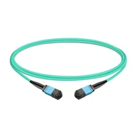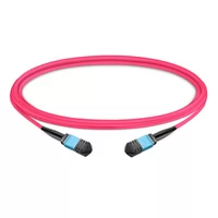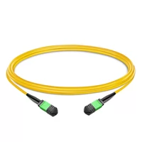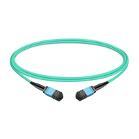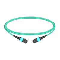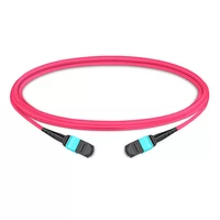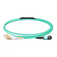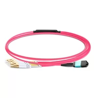

400G and 800G networks require particular MPO connector setups. The system will bring you costly project interruptions because of your incorrect choice, which also creates problems for acquiring new materials.
The guide provides you with all the necessary information about the subject matter. The program teaches you which MPO connector type each 400G/800G transceiver needs while you learn how to select your Base-8, Base-12, Base-16, and Base-24 options and discover migration paths that enable your upgrades without destroying your existing fiber plant.
400G and 800G Transceiver Types Explained
Not all 400G transceivers use the same fiber configuration. Understanding the differences is your first step to ordering the right MPO connectors.
400G-SR8: The MPO-16 Requirement
400G-SR8 is the most common multimode option for data centers. It uses 16 fibers – 8 for transmit and 8 for receive. Each lane runs 50G PAM4 signaling.
Key specs:
- Connector: MPO-16 (also called MTP-16)
- Fiber type: OM3, OM4, or OM5 multimode
- Distance: 70m on OM3, 100m on OM4/OM5
- Wavelength: 850nm
The MPO-16 connector has a unique offset key that prevents it from mating with standard MPO-12 or MPO-24 adapters. This is deliberate – it stops you from accidentally connecting incompatible fiber counts. See our MPO data center guide.
400G-DR4: The MPO-12 Single-Mode Option
400G-DR4 uses single-mode fiber and requires only 8 fibers (4 Tx + 4 Rx). Each lane runs 100G PAM4.
Key specs:
- Connector: MPO-12 (uses 8 of 12 fibers)
- Fiber type: OS2 single-mode
- Distance: 500m (DR4), up to 2km (DR4+)
- Wavelength: 1310nm
Here’s where it gets interesting. You can use MPO-12 connectors with 400G-DR4, but you’re only using 8 of the 12 fibers. That leaves 4 fibers unused – about 33% waste.
400G-SR4.2: The BiDi Alternative
400G-SR4.2 uses bidirectional transmission over 8 fibers via MPO-12. It sends and receives on the same fiber using different wavelengths (850nm and 910nm).
Key specs:
- Connector: MPO-12
- Fiber type: OM5 multimode (required for the wavelength split)
- Distance: 150m
- Advantage: Works with existing MPO-12 infrastructure
800G-SR8: Doubling Down on MPO-16
800G-SR8 essentially doubles 400G-SR8. It still uses MPO-16 connectors but pushes 100G per lane instead of 50G.
Key specs:
- Connector: MPO-16
- Fiber type: OM4 or OM5
- Distance: 100m
- Compatibility: Same fiber plant as 400G-SR8
This is actually good news if you’re planning ahead. Deploy MPO-16 for 400G today and you’re ready for 800G tomorrow without recabling.
LC Duplex Options: When You Don’t Need MPO
Not every 400G/800G application uses MPO connectors. The CWDM and LAN-WDM variants use standard LC duplex:
- 400G-FR4: 2km over single-mode (LC duplex)
- 400G-LR4: 10km over single-mode (LC duplex)
- 800G-2FR4: Two FR4 links bonded (2× LC duplex)
For a deeper dive into 400G and 800G transceiver options, see our OSFP transceiver guide.

MPO Connector Types: Base-8, Base-12, Base-16, Base-24
Choosing the right MPO fiber count isn’t just about what works today. It’s about your migration path and fiber utilization efficiency.
Base-8 (MPO-8): The Efficiency Champion
MPO-8 uses 8 fibers in a single row. It’s the sweet spot for parallel optics.
Best for:
- 40G SR4 (4 lanes)
- 100G PSM4 (4 lanes)
- 400G DR4 (4 lanes)
- 400G SR8 breakout to 200G
Fiber utilization: 100% with 8-fiber transceivers
Migration path: Clean upgrades from 40G → 100G → 400G-DR4 without changing cables
Base-8 is the industry recommendation for new single-mode deployments. You get perfect fiber utilization and a clear upgrade path. The downside? Limited availability compared to Base-12.
Base-12 (MPO-12): The Legacy Standard
MPO-12 has been the data center standard for over a decade. It uses 12 fibers in a single row.
Best for:
- Legacy 40G/100G infrastructure
- 400G DR4 (with 33% fiber waste)
- 400G SR4.2 (BiDi)
- Environments with existing MPO-12 plant
Fiber utilization: 67% with 8-fiber transceivers (4 fibers unused)
The math: If you’re running 400G-DR4 over MPO-12, you’re paying for 12 fibers but only using 8. That’s 33% waste on every cable. In a large deployment, that adds up fast. Click here to learn more about MPO-12 cable selection.
But if you’ve already got MPO-12 infrastructure everywhere, the waste might be cheaper than recabling. It depends on your scale.
Base-16 (MPO-16): The 400G Native
MPO-16 uses 16 fibers in a single row. It’s specifically designed for 400G-SR8 and 800G-SR8.
Best for:
- 400G-SR8 (perfect fit)
- 800G-SR8 (perfect fit)
- Future-proofing multimode deployments
Fiber utilization: 100% with SR8 transceivers
Critical detail: MPO-16 uses an offset key position. It physically cannot mate with MPO-12 or MPO-24 adapters. This prevents accidental mismating that could damage fiber end-faces.
If you’re deploying 400G-SR8, MPO-16 isn’t optional – it’s required. Plan your adapter panels accordingly.
Base-24 (MPO-24): The Hyperscale Choice
MPO-24 packs 24 fibers into the same footprint. It’s becoming popular in hyperscale data centers.
Best for:
- Ultra-high density applications
- Supporting two 400G-SR8 links per cable
- Supporting one 800G-SR8 link with spare capacity
- Reducing overall cable count
Fiber utilization: Flexible – use what you need
The advantage: One MPO-24 cable can replace two MPO-12 cables. That reduces your cable count by roughly 38%. Less congestion in cable trays, easier management, and lower installation labor.
The trade-off: Higher cost per cable and more complex polarity management.
Decision Matrix: Which Base Should You Choose?
| Your Situation | Recommended Base | Why |
| New single-mode build | Base-8 | 100% utilization, clean migration |
| Existing MPO-12 plant | Base-12 | Leverage existing infrastructure |
| 400G/800G multimode | Base-16 | Native fit, future-proof |
| Hyperscale new build | Base-24 | Maximum density, lowest cable count |
| Mixed environment | Hybrid approach | Base-16 for SR8, Base-8 for DR4 |
For help choosing between MTP and MPO connector grades, see our MPO vs MTP comparison.
MPO-16 Deep Dive for 400G-SR8 and 800G-SR8
Since MPO-16 is relatively new, let’s cover the details that matter for deployment.
The Offset Key Explained
The common industry standard for MPO-12 and MPO-24 connectors requires them to utilize a center key position. MPO-16 uses an offset key which his shifted to the side. This isn’t a manufacturing variation. It’s a deliberate design choice.
The offset key prevents you from accidentally plugging an MPO-16 cable into an MPO-12 adapter. Why does this matter? The fiber counts don’t match. The excessive force would result in damage because it would crush fibers while destroying end-faces.
Practical implication: You need MPO-16 specific adapters. The adapters use color-coded systems, which display as gray or white to differentiate between these two types of connectors and the MPO-12 connector, which displays as beige and aqua.
APC Polish Requirement
All 400G and 800G MPO connections require APC (Angled Physical Contact) polish. The 8-degree angle reduces back reflection.
Why APC matters for 400G:
- Return loss: ≥60 dB vs ≥35 dB for UPC
- Prevents reflected light from interfering with PAM4 signals
- Required by IEEE 802.3cm for 400G-SR8
Don’t mix APC and UPC connectors. They won’t mate properly, and you’ll damage the fiber end-faces.
Insertion Loss Budgets
400G-SR8 has a tight power budget. Every decibel matters.
Typical 400G-SR8 link budget:
- Total available: ~6.3 dB (with FEC enabled)
- Transceiver loss: ~1.5 dB per end (3.0 dB total)
- Available for cabling: ~3.3 dB
Connector loss by grade:
- Standard MPO: 0.50 dB per mated pair
- MTP: 0.35 dB per mated pair
- MTP Elite: 0.25 dB per mated pair
In a typical link with two patch panels (four mated pairs):
- Standard MPO: 2.0 dB connector loss
- MTP Elite: 1.0 dB connector loss
That 1 dB difference might determine whether your link comes up or stays down. For 400G and 800G, MTP Elite is often worth the premium.
400G/800G Breakout Configurations
One of the biggest advantages of MPO connectors is breakout flexibility. A single 400G port can fan out to multiple lower-speed connections.
400G DR4 to 4×100G Breakout
This is the most common migration scenario. You’re upgrading spine switches to 400G but keeping 100G at the leaf layer.
Configuration:
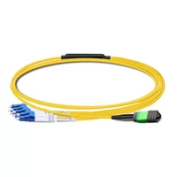
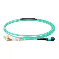
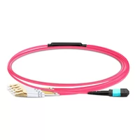
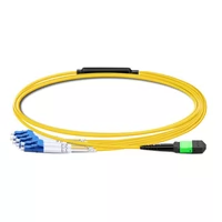
- 400G DR4 transceiver (MPO-12) at spine
- MPO-12 to 4× LC duplex breakout cable
- Four 100G DR transceivers (LC duplex) at leaf
Fiber mapping:
- Fiber 1-2: 100G lane 1
- Fiber 3-4: 100G lane 2
- Fiber 5-6: 100G lane 3
- Fiber 7-8: 100G lane 4
- Fibers 9-12: Unused (in Base-12)
Distance: Each 100G link supports up to 500m
400G SR8 to 2×200G Breakout
Useful when transitioning from 200G to 400G infrastructure.
Configuration:
- 400G SR8 transceiver (MPO-16) at spine
- MPO-16 to 2× MPO-8 breakout cable
- Two 200G SR4 transceivers (MPO-8) at leaf
Fiber mapping:
- Fibers 1-8: 200G SR4 link 1
- Fibers 9-16: 200G SR4 link 2
400G SR8 to 8×50G Breakout
For high-density server connectivity.
Configuration:
- 400G SR8 transceiver (MPO-16)
- MPO-16 to 8× LC duplex breakout harness
- Eight 50G SR transceivers (LC duplex)
This is particularly popular in hyper-scale environments where you’re driving multiple 50G server NICs from a single 400G switch port.
Breakout Cassette Approach
Instead of pre-terminated breakout cables, some deployments use breakout cassettes at the patch panel.
Advantages:
- More flexible – change breakout ratios by swapping cassettes
- Cleaner cable management
- Easier to reconfigure
Disadvantages:
- Higher insertion loss (two additional mated pairs)
- Higher cost
- More components to manage
For complex 400G/800G fiber deployments, see our complete MPO connector guide for detailed polarity and mapping strategies.
Link Budget and Performance Considerations
400G and 800G have stricter loss requirements than previous generations. Here’s how to calculate your margin.
400G-SR8 Link Budget Example
Let’s walk through a typical spine-to-leaf connection:
Components:
- Spine switch 400G-SR8: ~1.5 dB
- Patch panel 1 (mated pair): 0.35 dB (MTP)
- 50m OM4 trunk: 0.15 dB (3 dB/km)
- Patch panel 2 (mated pair): 0.35 dB (MTP)
- Leaf switch 400G-SR8: ~1.5 dB
Total loss: 3.85 dB
With ~6.3 dB available and 3.85 dB consumed, you’ve got 2.45 dB margin. That’s healthy.
When to Upgrade to MTP Elite
Standard MTP (0.35 dB) works for most 400G links with two or fewer patch panels. Consider MTP Elite (0.25 dB) when:
- You have three or more patch panels in the link
- You’re running near maximum distance
- You need maximum reliability margin
- You’re deploying 800G (tighter budgets)
Distance Limitations by Fiber Type
| Fiber Type | 400G-SR8 | 800G-SR8 |
| OM3 | 70m | Not supported |
| OM4 | 100m | 100m |
| OM5 | 100m | 100m |
Note: These distances assume standard loss budgets. If your link has higher loss (multiple patch panels, longer distances), your effective reach will be shorter.
Migration Strategy: From 100G to 400G/800G
The industry-standard approach lets you upgrade without forklift infrastructure replacement.
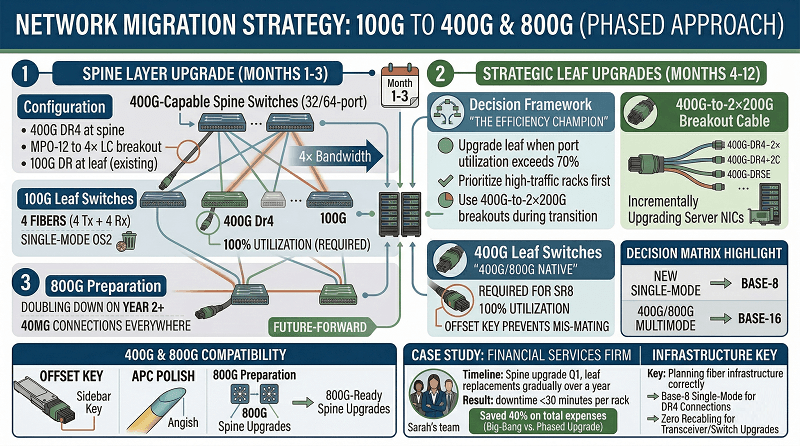
Phase 1: Spine Layer Upgrade (Months 1-3)
Actions:
- Deploy 400G-capable spine switches (32-port or 64-port)
- Use breakout cables to connect to existing 100G leaf switches
- Increase core bandwidth without touching leaf infrastructure
Configuration:
- 400G DR4 at spine
- MPO-12 to 4× LC breakout
- 100G DR at leaf (existing)
Result: 4× bandwidth increase at spine, zero disruption to leaf or server connectivity.
Phase 2: Strategic Leaf Upgrades (Months 4-12)
Actions:
- Replace leaf switches to 400G as traffic demands grow
- Keep using breakout where 100G servers remain
- Upgrade server NICs incrementally
Decision framework:
- Upgrade leaf when port utilization exceeds 70%
- Prioritize high-traffic racks first
- Use 400G-to-2×200G breakouts during transition
Phase 3: Full 400G End-to-End (Year 2+)
Actions:
- Remove breakout configurations
- Deploy direct 400G connections everywhere
- Prepare for 800G spine upgrades
Sarah’s team at a financial services firm used this approach. They upgraded their spine to 400G in Q1, then replaced leaf switches gradually throughout the year. The total downtime for each rack stayed below 30 minutes. The big-bang upgrade approach saved the organization approximately 40% of its total expenses.
The key was planning the fiber infrastructure correctly from the start. The organization used Base-8 single-mode for their DR4 connections because it allowed them to switch transceivers and switches without needing to recable.
For detailed 400G deployment architectures, see our OSFP deployment guide.
Common Deployment Mistakes to Avoid
We’ve seen these errors cost projects time and money.
Ordering MPO-12 for 400G-SR8.
The most expensive mistake. MPO-12 and MPO-16 are physically incompatible. Double-check your transceiver specs before ordering cables.
Using UPC instead of APC.
400G and 800G require APC polish. UPC won’t provide sufficient return loss performance. Check the connector end-faces with a scope before installation.
Wrong polarity method.
400G parallel optics require Method B (Key-Up to Key-Up). Method A will cause Tx/Rx mismatches. Verify polarity before turning up links.
Mixing MTP Elite with standard MPO.
The connection works, but your loss budget calculations become unreliable. Stick to one grade per link for predictable performance.
Ignoring the bend radius.
MPO-16 and MPO-24 cables are stiffer than duplex fiber. Respect the 30mm minimum bend radius. Tighter bends create microbends and insertion loss.
Forgetting about gender.
Female (no pins) goes on the equipment. Male (with pins) extends trunks. Getting this backwards means ordering adapters or replacement cables.
FAQ
Can I use MPO-12 for 400G-SR8?
No. 400G-SR8 requires MPO-16 (16 fibers). MPO-12 only provides 12 fibers. Even if you tried to force them together, the offset key on MPO-16 prevents mating with MPO-12 adapters. Order MPO-16 for SR8 deployments.
What’s the difference between Base-8 and Base-16?
Base-8 uses 8 fibers and is optimized for 40G/100G/400G-DR4. Base-16 uses 16 fibers and is required for 400G-SR8 and 800G-SR8. Base-8 provides 100% fiber utilization with DR4; Base-16 provides 100% utilization with SR8.
Do I need MTP Elite for 400G?
It depends on your link complexity. Standard MTP (0.35 dB) works for simple links with one or two patch panels. Use MTP Elite (0.25 dB) when you have three or more patch panels, long distances, or need maximum reliability margin. For 800G, MTP Elite is strongly recommended.
How do I migrate from 100G to 400G without recabling?
Use breakout cables. Deploy 400G at the spine layer with 400G-to-4×100G breakout cables connecting to existing 100G leaf switches. Upgrade leaf switches incrementally as needed. For single-mode DR4, use Base-8 infrastructure. For multimode SR8, use Base-16.
Can I upgrade from 400G to 800G on the same fiber?
Yes, if you planned ahead. 400G-SR8 and 800G-SR8 both use MPO-16 connectors. If your fiber plant supports 400G-SR8 today, it will support 800G-SR8 tomorrow. You’ll just swap transceivers and switches.
Conclusion
400G and 800G networks demand specific MPO connector configurations. The choices you make today – Base-8 vs Base-12 vs Base-16 – will affect your upgrade options for years.
Key takeaways:
- 400G-SR8 and 800G-SR8 require MPO-16 connectors
- 400G-DR4 works with MPO-8 or MPO-12 (with fiber waste)
- Base-8 offers the cleanest migration path for single-mode
- Breakout cables enable phased upgrades without recabling
- MTP Elite is worth the premium for complex 400G/800G links
Plan your fiber infrastructure once, plan it right. The cost of getting MPO connectors wrong far exceeds the cost of doing the analysis upfront.
Ready to deploy 400G or 800G in your data center? Contact our fiber connectivity experts for a free consultation on MPO connector specifications and migration strategies tailored to your infrastructure.
Related Products:
-
 1m (3ft) 12 Fibers Female to Female MPO Trunk Cable Polarity B LSZH OM3 50/125 Multimode Fiber
$20.00
-
1m (3ft) 12 Fibers Female to Female MPO Trunk Cable Polarity B LSZH Multimode OM4 50/125
$21.00
-
1m (3ft) 12 Fibers Female to Female MPO Trunk Cable Polarity B LSZH OS2 9/125 Single Mode
$26.00
-
1m (3ft) 12 Fibers Low Insertion Loss Female to Female MPO Trunk Cable Polarity B LSZH OM3 50/125 Multimode Fiber
$32.00
-
1m (3ft) 12 Fibers Female to Female Elite MTP Trunk Cable Polarity B LSZH OM3 50/125 Multimode Fiber
$35.00
-
1m (3ft) 12 Fibers Female to Female Elite MTP Trunk Cable Polarity B LSZH Multimode OM4 50/125
$36.00
-
1m (3ft) MPO UPC Female to 4 LC UPC Duplex OM3 50/125 Multimode Fiber Breakout Cable, 8 Fibers, Type B, LSZH, Aqua
$20.00
-
1m (3ft) MPO UPC Female to 4 LC UPC Duplex OM4 50/125 Multimode Fiber Breakout Cable, 8 Fibers Type B, LSZH, Aqua/Violet
$23.00
-
1m (3ft) MPO APC Female to 4 LC UPC Duplex OS2 9/125 Single Mode Fiber Breakout Cable, 8 Fibers Type B, LSZH, Yellow
$24.00
-
1m (3ft) MTP Female to 4 LC UPC Duplex OM3 50/125 Multimode Fiber Breakout Cable, 8 Fibers, Type B, Elite, Plenum (OFNP), Aqua
$28.00
-
1m (3ft) MTP Female to 4 LC UPC Duplex OM4 50/125 Multimode Fiber Breakout Cable, 8 Fibers, Type B, Elite, Plenum (OFNP), Aqua/Violet
$30.00
-
1m (3ft) MTP APC Female to 4 LC UPC Duplex OS2 9/125 Single Mode Fiber Breakout Cable, 8 Fibers, Type B, Elite, Plenum (OFNP), Yellow
$32.00