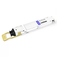
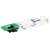
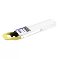
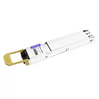
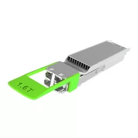
The current infrastructure you create for data centers needs to handle 1.6 terabits of data traffic on the following day. Data center architects must decide on their infrastructure design choices, which will determine their operational capacity during the next ten years, according to the forecasted shipment of more than six million 800G OSFP modules in 2025. The widespread use of high-speed optical interconnects in AI infrastructure deployment faces challenges because deployment teams need to determine their hardware design requirements and develop their system performance capabilities and operational transition methods.
High-density rack installations of OSFP require proper planning to prevent expensive operational breakdowns. The 800G modules consume power at a rate of 25W per port or higher. The 32-port switch consumes more than 1,300W just to operate its optical modules when all its ports are in use. The installation process needs to address three main factors, which include thermal management, hardware compatibility, and structured cabling needs.
The complete guide to OSFP infrastructure deployment includes all steps needed for planning, implementation, and system performance improvement. The training program teaches users how to design spine-leaf network architectures, perform pre-deployment planning, apply a three-phase migration process, execute installation procedures, and fix system problems. The guide provides complete infrastructure lifecycle coverage, which includes planning, artificial intelligence cluster development, and system performance enhancement.
For a comprehensive overview of OSFP technology fundamentals, see our complete guide to OSFP transceivers.
Understanding OSFP for Modern Data Centers
What is OSFP? Technical Overview
The OSFP (Octal Small Form-factor Pluggable) optical transceiver module operates at high-speed data center networking. The module supports eight electrical lanes, which permit transmission speeds of 400G and 800G and the upcoming 1.6T standard. Each lane operates at 56G PAM4 for 400G, 112G PAM4 for 800G, and 224G PAM4 for 1.6T configurations.
The OSFP form factor measures 22.5mm wide by 38.0mm deep, which makes it larger than QSFP-DD modules. The increased dimensions of the system permit the integration of thermal management components while creating extra space to release heat. The module includes a management interface based on CMIS 5.0/5.2, which enables users to track temperature levels, optical power measurements, and system diagnostic data.
OSFP modules support multiple optical interfaces, including SR8 (100m over multimode fiber), DR8 (500m over single-mode fiber), FR8 (2km), LR8 (10km), and 2FR4 (2km via duplex fiber). This range of options supports diverse data center interconnect scenarios from intra-rack connections to longer-distance spine-leaf links.

OSFP vs QSFP-DD: Decision Framework
Choosing between OSFP and QSFP-DD requires evaluating current needs against future requirements. Both form factors support 400G and 800G speeds, but their design philosophies differ significantly.
Choose OSFP when:
- Building new infrastructure without legacy constraints
- Planning for 1.6T migration path
- Deploying high-density AI clusters requiring maximum thermal headroom
- Standardizing on switch platforms with native OSFP support (Arista, Cisco 8000 series, NVIDIA Spectrum-4)
Choose QSFP-DD when:
- Upgrading existing QSFP28/QSFP+ infrastructure
- Leveraging already-deployed switch hardware
- Requiring backward compatibility with lower-speed modules
- Minimizing immediate capital expenditure on switch upgrades
The decision becomes critical when considering thermal performance. Real-world deployments show OSFP modules run 2-3°C hotter than QSFP-DD equivalents under identical conditions. However, OSFP’s larger heat sink surface area and superior thermal interface often provide better long-term reliability at 800G speeds. For a detailed comparison, see our OSFP vs QSFP-DD analysis.
OSFP Form Factor Variants: IHS vs RHS
The OSFP modules exist as two separate thermal options that customers must choose between, which are different from each other. The need to comprehend this difference exists because it helps organizations avoid expensive errors during their buying process.
OSFP-IHS (Integrated Heat Sink) contains an embedded heat sink that operates as a cooling solution for switches with external heat sink cages. The module’s heat sink connects directly to the switch cage’s thermal management system. IHS modules sit flush with the switch faceplate when properly installed.
OSFP-RHS (Riding Heat Sink) lacks an integrated heat sink and requires the switch cage to provide thermal management. The devices operate with network interface cards (NICs), and they function in switches that use direct module cooling technology. The RHS modules need more space because they extend beyond the faceplate distance requirements.
The process of verifying compatibility needs users to compare switch specifications with the module datasheet documentation. The installation of an IHS module into an RHS cage leads to improper thermal connection, which increases the risk of equipment failure. The IHS cages do not allow the RHS modules to properly seat, while they fail to supply sufficient cooling capacity. The cage type needs to be checked before buying.

OSFP Data Center Architecture Design
Spine-Leaf Architecture with OSFP
Spine-leaf topology has become the standard for modern data center networks, and OSFP modules enable unprecedented scale in these fabrics. The use of 64-port 800G spine switches in a two-tier spine-leaf design enables the system to handle 8,192 400G NIC ports, which allows for future cluster expansion.
800G Spine with 400G Leaf Configurations
The most common deployment pattern uses 800G OSFP ports on spine switches with 400G leaf switches. The setup employs breakout cables which convert 800G into two 400G outputs to achieve optimal port usage while keeping cable thickness at an acceptable level. The system connects one 800G spine port to two 400G leaf switches which results in a 50 percent decrease of spine switch usage when compared to direct 400G installations.
The system uses 32-port 800G spine switches together with 32-port 400G leaf switches in this deployment scenario. The spine switch provides a total fabric capacity of 32×800G which equals 25.6T. The system supports 64 leaf switches at 400G each through breakout cables, which results in 2,048 400G server-facing ports with 3:1 oversubscription that AI training clusters commonly use.

Full 800G End-to-End Topologies
Organizations building AI infrastructure increasingly deploy native 800G throughout the fabric. This approach removes the need for breakout cables while creating a simpler system that decreases optical loss. NVIDIA’s DGX SuperPOD architecture demonstrates this method by utilizing 800G OSFP for complete GPU-to-GPU connections during large language model training.
Organizations need to implement precise oversubscription strategies when they want to use 800G technology throughout their operations. The standard design for AI clusters utilizes 64-port 800G spine switches together with 64-port 800G leaf switches to establish 1:1 oversubscription for east-west traffic patterns which distributed training workloads typically require.
AI/HPC Cluster Architectures
The OSFP modules from AI infrastructure requirements which OSFP modules from AI infrastructure requirements. GPU clusters need their communication operations to use high bandwidth and low latency with performance metrics which remain constant throughout their operation.
GPU Interconnect Requirements
Modern AI clusters connect their multiple racks to thousands of GPUs which span their entire setup. The OSFP standard provides a suitable solution for scale-out fabrics at NVIDIA H100 and newer GPUs which support 400G and 800G network interface cards. A 1,024 GPU cluster needs about 128 800G leaf ports because it will use eight GPUs per leaf which requires spine switches to have high port capacity.
AI networking now relies on RoCEv2 (RDMA over Converged Ethernet v2) as its main networking protocol. The OSFP modules meet RoCEv2 lossless Ethernet requirements through their support of Priority Flow Control and Explicit Congestion Notification. Network designers must ensure switches support these features when planning AI clusters.
Scale-Out Fabric Design
AI systems that require large-scale implementation need more networking resources than a single spine-leaf pod can provide. Multi-pod designs connect spine layers through additional switching tiers or direct inter-pod links. OSFP technology supports 2km distance connections through its FR8 and 2FR4 modes which allow these links to operate without needing signal regeneration.
A typical hyperscale AI deployment might include 8,192 GPUs organized in 64 pods of 128 GPUs each. Each pod contains 16 leaf switches with 800G uplinks to 32 spine switches. The system delivers complete bisection bandwidth which enables intra-pod communication while sustaining high-performance inter-pod network connections.
Migration-Friendly Hybrid Designs
Organizations rarely replace entire networks simultaneously. Hybrid designs supporting multiple speeds enable phased migrations while maintaining service continuity.
Breakout Cable Strategies
Breakout cables provide the foundation for hybrid deployments. An 800G OSFP port connects via breakout cable to multiple 400G or 200G devices. Common configurations include:
- 800G to 2×400G: Connects two 400G leaf switches to one 800G spine port
- 800G to 4×200G: Supports legacy 200G infrastructure during transition
- 800G to 8×100G: Maximizes compatibility with existing 100G server ports
The fiber cabling infrastructure needs to accommodate the specified breakout patterns. The 800G SR8/DR8 standard uses MPO-16 connectors which connect to MPO-8 or duplex LC for lower-speed connections. The correct fiber polarity combined with sufficient patch panel capacity enables organizations to avoid expensive re-cabling needs during system upgrades.
Multi-Speed Coexistence Planning
Flexible port configuration designs help switches operate successfully in environments that use multiple connection speeds. The Arista 7800R4 and Cisco 8111 platforms support 800G/400G/200G/100G operation on the same ports through software configuration. Network architects use the flexibility to build high-speed spine networks which work together with their current leaf equipment.
Planning for coexistence requires an examination of management challenges. The existence of multiple speeds results in organizations needing to manage different types of transceivers and cable types and troubleshooting methods. The operational workload decreases when organizations choose to work with particular speed levels which include 100G/400G/800G instead of using intermediate speeds.
Pre-Deployment Planning and Requirements
Power and Thermal Budgeting
Accurate power planning prevents deployment surprises. While datasheets provide typical power consumption, real-world measurements often exceed these figures, particularly at 800G speeds.
Power Consumption by Speed Grade
| Speed | Typical Power | Max Power | Notes |
| 400G SR8 | 12-15W | 18W | Short reach, lower power |
| 400G DR8 | 15-18W | 20W | Common for data center |
| 800G SR8 | 14-17W | 20W | Early generation higher |
| 800G DR8 | 18-22W | 25W+ | Real deployments report 25W |
| 1.6T DR8 | 15-25W | 33W | Emerging technology |
These figures represent module power only. Additional power consumption from switch ASICs, cooling fans, and power supply inefficiencies must be included in total rack power budgets.
Rack-Level Power Calculations
A standard 32-port 800G switch consumes 1,200-1,500W power when all OSFP modules operate at maximum capacity. The total power consumption for a switch increases to 1,600-2,100W when base power 400-600W of modern 51.2T switches gets added to the switch base power. The installation of four switches per rack needs between 6.4 and 8.4 kilowatts of power which does not include the needs of storage and computing equipment.
Power distribution units must deliver sufficient capacity with additional capacity built in to handle upcoming requirements. The 10kW rack PDU operates four 800G switches while maintaining a small power reserve. The design requires 12-15kW power per rack to support higher-density setups while enabling 1.6T system expansions.
Cooling Requirements
OSFP modules need 3-4 m/s airflow to maintain their operational reliability across the entire module surface. The switch specifications specify needed cubic feet per minute (CFM) values which require rack-level cooling systems to include exhaust air recirculation and hot spot formation as design parameters.
Raised floor environments should deliver 300-400 CFM per kW of rack power. The overhead cooling systems need exact air handler locations to maintain system efficiency which protects against operational failures. The high-density OSFP installations make use of in-row cooling systems because it delivers dependable thermal control solutions.
OSFP modules operate 2-3 degrees Celsius above the temperature of similar QSFP-DD modules according to actual field tests. The temperature difference needs operational management because it reaches a critical point for facilities that operate close to their thermal boundaries. The system achieves extra cooling capacity through the temperature increase from 22°C to 25°C which causes no major energy costs.
For detailed thermal management guidance, see our OSFP thermal management guide.
Fiber Infrastructure Assessment
OSFP modules for data center applications primarily use parallel optics, requiring multi-fiber connectors and careful polarity management.
Fiber Types by Application
- OM4/OM5 Multimode: Supports SR8 modules up to 100m. Cost-effective for intra-rack and adjacent-rack connections. MPO-16 connectors required for 8-lane operation.
- OS2 Single-Mode: Required for DR8 (500m), FR8 (2km), and LR8 (10km) modules. Standard yellow jacket fiber. MPO-16 or duplex CS/SN connectors depending on module type.
Single-mode fiber dominates new 800G deployments due to lower optical loss and future-proofing for 1.6T. Multimode remains viable for high-density, short-reach applications where cost sensitivity outweighs future upgrade concerns.
MPO Connector Requirements
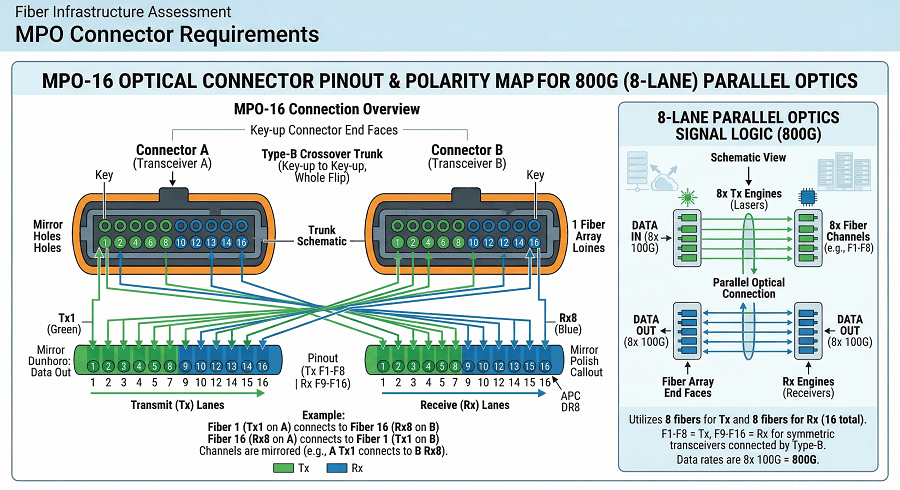
The OSFP SR8 and DR8 modules utilize MPO-16 connectors, which contain 16 fibers arranged in a row of 16. The single-mode applications require APC (Angled Physical Contact) polish because it prevents reflections, which lead to bit errors. The UPC Polish works for multimodal applications, but testing shows it does not provide future protection.
The reliability of links depends on the quality of connectors used in their construction. The testing conducted by industry experts shows that 70% of DR4 failures in previous technology systems occur because connectors have been contaminated or soiled. The installation process needs to implement cleaning procedures because they stop these failures from occurring.
Polarity Schemes and Structured Cabling
MPO polarity defines the relationship between transmit and receive fibers across a link. Three polarity methods exist (Method A, B, C), and mixed methods within a channel cause connectivity failures.
Structured cabling for OSFP should use:
- MPO-16 trunk cables for 800G connections
- Consistent polarity method throughout the infrastructure
- Properly labeled patch panels indicating fiber count and polarity
- Adequate slack management to prevent bend radius violations
Pre-deployment fiber testing, including OTDR characterization and insertion loss measurement, identifies issues before switch installation begins.
Hardware Compatibility Verification
Incompatible modules cause deployment delays and added expense. Verification procedures prevent costly mistakes.
Switch Cage Type Verification
Confirm switch cage specifications before module procurement:
- Check switch datasheet for IHS or RHS cage type
- Verify thermal management specifications match module requirements
- Confirm management interface version (CMIS 5.0 vs 5.2)
Common switch platforms and their OSFP support:
- Arista 7800R4: IHS cages, native 800G support
- Cisco 8111/8100: IHS cages, 800G ready
- NVIDIA Spectrum-4: IHS cages, optimized for AI workloads
- Juniper QFX10000: Check specific model for OSFP support
Heatsink Verification Checklist
For IHS modules, verify:
- Switch cage includes heat sink mechanism
- Heat sink pressure is within module specification
- No physical interference with adjacent ports
- Adequate clearance for module insertion/extraction
For RHS modules, verify:
- Switch provides adequate airflow (CFM specification)
- Ambient temperature within module operating range
- No additional heat sink components required
Vendor Compatibility Matrix
While OSFP is an MSA standard, implementation details vary between vendors. Digital diagnostic monitoring (DDM) information display, alarm thresholds, and management commands differ between switch platforms.
Test module compatibility in non-production environments before large-scale deployment. Verify:
- Module recognition and identification
- Optical power reading accuracy
- Temperature monitoring
- Alarm and threshold configuration
Phased Deployment Strategy
Phase 1: Spine Layer Deployment
Begin migration at the spine layer, establishing high-capacity infrastructure before upgrading leaf switches.

Upgrade Spine Switches First
You must implement 800G-capable spine switches together with your present system. This method establishes instant capacity needs for upcoming leaf system enhancements while maintaining current operational activities. The configuration requires spine switches to use breakout cables which will link to both 400G and 100G existing leaf infrastructure.
A typical deployment will use two 64-port 800G switches to replace four old spine switches. Each new spine port uses 800G-to-2×400G breakout cables to link with two existing leaf switches while keeping all current connections active and expanding future capacity.
Breakout Connectivity to Existing Leaf
Breakout cables enable spine-first upgrades by translating between 800G spine ports and lower-speed leaf ports. During this transition phase:
- Monitor breakout cable insertion loss carefully
- Document which spine ports serve which leaf switches
- Plan polarity to ensure proper transmit/receive alignment
The breakout phase typically lasts 3-6 months while leaf switches are upgraded. During this period, maintain careful documentation to prevent connectivity errors during the final transition to native speeds.
Validation and Monitoring
Before proceeding to Phase 2, verify spine layer stability:
- Confirm all breakout links operate at expected optical power levels
- Monitor bit error rates for 24-48 hours under production traffic
- Document baseline performance metrics for comparison during later phases
- Verify switch management and monitoring systems function correctly
Phase 2: Leaf Switch Migration
With spine infrastructure in place, migrate leaf switches using a rack-by-rack approach.
Rack-by-Rack Migration Approach
Select migration candidates based on:
- Traffic patterns (migrate lower-priority racks first)
- Physical location (minimize cable runs during transition)
- Maintenance windows (coordinate with application teams)
For each rack:
- Pre-stage new leaf switches with configuration
- Migrate server connections in groups of 8-16 ports
- Verify each group before proceeding
- Complete full rack migration before moving to next rack
This approach limits the blast radius if issues arise. A failed leaf switch affects only one rack rather than the entire network segment.
Maintaining Service During Transition
For critical applications, maintain service through redundant connectivity:
- Dual-homed servers connect to both old and new leaf switches during migration
- Load balancers distribute traffic across available paths
- Maintenance windows are scheduled for final cutover of single-homed devices
Communicate migration schedules to application teams. Provide 48-72 hours’ notice for each rack to allow preparation and verification of application functionality post-migration.
Testing Procedures
After each leaf switch migration:
- Verify optical power levels on all spine-facing links
- Confirm link up at expected speed (no auto-negotiation to lower speed)
- Test server connectivity and performance
- Monitor for packet loss or errors
Document any issues and resolutions. Patterns in early migrations inform procedures for later racks, improving efficiency as the process continues.
Phase 3: Native High-Speed Operation
With all leaf switches upgraded, transition to native high-speed connectivity.
Removing Breakout Cables
Replace breakout cables with direct OSFP-to-OSFP connections:
- Remove 800G-to-2×400G breakout cables
- Install direct 800G OSFP cables (AOC or DAC for short reach)
- Verify links established at 800G native speed
This transition doubles effective spine port capacity, improving oversubscription ratios and reducing latency from electrical muxing in breakout cables.
End-to-End Optimization
With native 800G throughout the fabric, optimize for performance:
- Adjust buffer settings for 800G line rates
- Configure ECN thresholds appropriate for higher bandwidth
- Optimize routing for reduced path stretch
Update monitoring thresholds to reflect new operating parameters. Alarm levels appropriate for 400G may not trigger until significant degradation occurs at 800G speeds.
Performance Validation
Conduct comprehensive performance testing:
- Measure throughput between rack pairs
- Verify latency meets design specifications
- Test failover behavior under link failures
- Validate RoCEv2 performance for AI workloads if applicable
Document final performance benchmarks. These measurements serve as baselines for future troubleshooting and capacity planning.
OSFP Installation Best Practices
Step-by-Step Installation Procedures
Proper installation prevents the majority of OSFP deployment issues. Follow these procedures for reliable operation.
ESD Protection
OSFP modules contain electrostatic-sensitive components. Always:
- Use grounded wrist straps when handling modules
- Store modules in anti-static packaging until installation
- Avoid touching optical interfaces or electrical contacts
- Work in ESD-safe environments with proper humidity (40-60% relative humidity)
Static discharge can damage laser diodes or receiver electronics without immediate visible symptoms. Modules may function initially but fail prematurely after field deployment.
Module Insertion Techniques
Insert OSFP modules using proper technique:
- Remove protective caps from module optical interfaces
- Align module with cage, ensuring proper orientation (keying prevents incorrect insertion)
- Insert module with steady, even pressure until connector seats
- Verify module latch engages fully (audible click on most cages)
- For IHS modules, verify thermal pad contact with cage heat sink
Never force a module that does not insert smoothly. Misalignment can damage cage connectors or module electrical contacts. If resistance occurs, withdraw and re-align before retrying.
Fiber Cleaning and Inspection
Clean fiber connectors before every insertion. Industry data shows 70% of parallel optic failures result from contaminated connectors.
Cleaning procedure:
- Inspect connector with fiber microscope (200x or 400x magnification)
- If contamination visible, clean with lint-free wipes and appropriate solvent
- Re-inspect to verify cleanliness
- Clean module receptacle with appropriate swab
- Connect fiber and verify link establishment
For MPO connectors, use specialized cleaning tools designed for multi-fiber arrays. Single-fiber cleaning methods are ineffective and may push debris into adjacent fibers.
Cabling and Connectivity
Proper cable management ensures reliable operation and simplifies future maintenance.
MPO Cable Management
OSFP modules with MPO connectors require careful cable management:
- Maintain minimum bend radius (30mm for most trunk cables)
- Use cable management hardware to support cable weight
- Route cables to avoid sharp edges or pinch points
- Label both ends of every cable with unique identifiers
MPO trunk cables are less flexible than duplex fiber. Plan routing paths that accommodate cable stiffness while maintaining bend radius requirements.
Breakout Configurations
When using breakout cables, document the fanout pattern clearly:
- Label each leg of breakout cable with corresponding spine/leaf port
- Color-code breakout legs by destination
- Maintain consistent polarity across all breakout cables
Common breakout patterns:
- 800G to 2×400G: Each 400G leg uses 4 lanes
- 800G to 4×200G: Each 200G leg uses 2 lanes
- 800G to 8×100G: Each 100G leg uses 1 lane with gearbox
Labeling and Documentation
Comprehensive labeling prevents errors during troubleshooting and maintenance:
- Label all OSFP modules with unique identifiers
- Document fiber path from module to patch panel
- Maintain as-built drawings showing all connections
- Record module serial numbers for warranty and support
Digital documentation tools enable quick path tracing during outages. Consider cable management software that integrates with switch port databases.
For detailed installation procedures, see our 400G OSFP implementation guide.
Configuration Examples
Arista EOS Configuration
Enable RS-FEC (mandatory for 400G/800G):
interface Ethernet1/1
speed 800000full
fec rs
no shutdown
Verify module status:
show interfaces Ethernet1/1 transceiver
show interfaces Ethernet1/1 counters errors
Cisco NX-OS Configuration
Configure 800G interface with RS-FEC:
interface Ethernet1/1
speed 800000
fec rs
no shutdown
Monitor optical levels:
show interface Ethernet1/1 transceiver detail
show fec event-history interface Ethernet1/1
FEC Requirements
RS-FEC (Reed-Solomon Forward Error Correction) is mandatory for 400G and 800G operation. The 544/514 coding scheme provides correction of up to 15 bit errors per 544-bit block. Both ends of a link must use matching FEC modes:
- RS-FEC (544,514): Standard for 400G/800G Ethernet
- RS-FEC (544,514) – 544/514: Required for 800G operation
- FC-FEC: Not supported for OSFP at these speeds
FEC mismatches result in link establishment failures or degraded performance. Configure FEC explicitly rather than relying on auto-negotiation to prevent mismatches.
Troubleshooting Common OSFP Deployment Issues
Link Issues
No Link / Link Flapping
When links fail to establish or flap repeatedly:
- Verify optical power: Check Tx/Rx power levels against module specifications. Received power below the sensitivity minimum prevents link establishment.
- Inspect fiber connectors: Clean both module and cable connectors. Contamination is the most common cause of link issues.
- Check polarity: Ensure transmit fibers align with receive fibers. Reversed polarity results in no light reaching the receiver.
- Verify FEC configuration: Mismatched FEC modes between ends cause link flapping. Both sides must use RS-FEC (544,514).
- Test with known-good components: Swap suspected faulty modules or cables with known-working spares to isolate failures.
FEC Mismatches
Symptoms include link establishment followed by immediate drop, or links that establish but show high error rates.
Resolution:
- Configure FEC mode explicitly on both ends
- Use RS-FEC (544,514) for 400G/800G operation
- Verify switch software version supports required FEC mode
Polarity Problems
Parallel optics require correct fiber mapping. Symptoms include partial link (some lanes up, others down) or no link with good optical power.
Resolution:
- Verify MPO polarity using visual fault locator
- Check cable documentation for polarity method (A, B, or C)
- Ensure consistent polarity throughout the channel
Thermal and Power Issues
High Temperature Alarms
OSFP modules generate substantial heat. High temperature alarms indicate:
- Inadequate airflow: Verify switch cooling fans operational, air filters clean, rack exhaust not blocked.
- IHS/RHS mismatch: Module running without proper thermal contact. Verify module type matches cage design.
- Ambient temperature exceeded: Verify data center cooling maintains intake temperature below module maximum (typically 70-75°C module case temperature, corresponding to lower ambient).
Thermal shutdown typically occurs at 80-85°C module case temperature. Sustained operation above 70°C reduces module lifetime.
Power Budget Exceeded
When rack power consumption exceeds capacity:
- Calculate actual consumption: Use measured values, not datasheet typicals. Real 800G modules often exceed 20W.
- Stagger switch boot sequences: Prevent simultaneous inrush current from tripping breakers.
- Upgrade power distribution: Install higher-capacity PDUs or add circuits before additional switch deployment.
Performance Issues
High Bit Error Rate
Elevated errors indicate signal integrity issues:
- Check optical power levels: Both insufficient and excessive received power cause errors.
- Verify fiber quality: High loss or reflections from poor connections degrade signal.
- Inspect for cable stress: Sharp bends or cable crush affect signal integrity.
- Confirm FEC operation: Verify FEC is correcting errors rather than reporting uncorrectable errors.
Acceptable pre-FEC bit error rates are typically 10^-4 to 10^-5. Post-FEC error rates should be effectively zero for properly functioning links.
Latency Problems
Unexpected latency in OSFP deployments may indicate:
- Excessive cable length: Verify fiber length matches link budget calculations.
- Switch buffer issues: High buffer utilization causes queueing delay. Monitor buffer occupancy during traffic peaks.
- Breakout cable latency: Active breakout cables introduce additional latency from electrical retiming. Use direct connections when latency is critical.
Future-Proofing: 800G to 1.6T Migration Path
1.6T OSFP Roadmap
The transition to 1.6T is already underway, with modules entering commercial production in 2025.
OSFP1600 Specifications
OSFP1600 maintains the same physical form factor as 400G/800G OSFP, enabling backward compatibility with existing switch cages. Key specifications include:
- 8 lanes × 200G PAM4 signaling (224G electrical)
- Same mechanical envelope as existing OSFP
- Enhanced thermal management for up to 33W module power
- CMIS 5.2 management interface
This backward compatibility protects infrastructure investment. Switch platforms designed for 800G OSFP typically support 1.6T modules through software upgrades, though thermal design must accommodate higher power.
OSFP-XD for 3.2T Future
For beyond 1.6T, the OSFP-XD (Extra Density) form factor doubles lane count to 16. This provides a path to 3.2T without requiring new management interfaces or fundamental architectural changes. OSFP-XD modules are approximately 5mm taller than standard OSFP.
Backward Compatibility Considerations
When designing new infrastructure:
- Specify switch cages rated for 1.6T thermal loads
- Ensure fiber infrastructure supports 1.6T reaches (2km+ for typical data center)
- Plan power distribution for 30W+ per module
- Consider active cooling solutions for highest-density deployments
Organizations deploying 800G infrastructure today should verify 1.6T readiness to avoid premature obsolescence.
LPO and CPO Considerations
Linear Pluggable Optics (LPO) and Co-Packaged Optics (CPO) represent evolutionary paths beyond traditional pluggable modules.
Linear Pluggable Optics Benefits
LPO modules eliminate the DSP (Digital Signal Processor) from the optical module, reducing power consumption by 30-50%. A typical 800G LPO module consumes 10-14W versus 18-25W for standard DSP-based modules.
Trade-offs include:
- Shorter reach limitations (typically <2km)
- Stricter host switch requirements for signal conditioning
- Limited management capabilities without DSP
When to Consider LPO
LPO is appropriate when:
- Deploying high-density clusters with short reach requirements
- Power consumption is the primary constraint
- Switch platforms support LPO signal conditioning
- Migration to CPO is planned within 3-5 years
Co-Packaged Optics Outlook
CPO technology establishes optical engines as permanent components on switch ASIC packages, which completely removes the need for pluggable modules. The system achieves a 40-50% power reduction when compared to pluggable optics, while the system also supports higher port density operations.
The introduction of CPO systems will take place during the period from 2026 to 2027 to support maximum capacity AI research facilities. Organizations that need to build infrastructure for more than five years should keep track of CPO advancements because pluggable OSFP remains the main option until 2027-2028.
For more on 1.6T technology, see our 1.6T OSFP InfiniBand guide.
Frequently Asked Questions
What is OSFP in data center networking?
OSFP (Octal Small Form-factor Pluggable) is an optical transceiver module which provides eight electrical lanes for transmitting data at 400G, 800G and 1.6T speeds. The standard provides higher port density and improved thermal management capabilities which people now use for AI applications and high-performance data center networks.
How do I choose between OSFP and QSFP-DD?
OSFP should be selected for new installation projects which require 800G+ speeds and AI clusters that need complete thermal capacity. QSFP-DD should be selected for existing systems which have old equipment or need to support devices that operate at lower speeds.
What are the power requirements for OSFP modules?
The 400G OSFP modules need between 12 and 18 watts of power while 800G modules need between 18 and 25 watts. The 32-port 800G switch needs between 1,300 and 1,550 watts to operate its optical modules and requires an additional 400 to 600 watts for its switching operation. The power consumption of all racks should be calculated in advance.
How do you cool OSFP modules in high-density racks?
The OSFP modules need 3-4 m/s airflow to function while operating 2-3°C hotter than QSFP-DD. The switches must provide sufficient cooling power while the system needs to keep intake temperatures below 25°C with the IHS/RHS system needing thermal interface contact verification.
What fiber types work with OSFP?
OSFP SR8 uses OM4/OM5 multimode fiber (up to 100m). The OSFP DR8 and FR8 and LR8 support OS2 single-mode fiber for distances of 500m and 2km and 10km respectively. The standard connector for parallel optic variants uses MPO-16 connectors.
Can I mix OSFP and QSFP-DD in the same infrastructure?
The system allows users to use switch platforms that support both form factors or transition between different phases. However, OSFP and QSFP-DD modules are not interchangeable in the same port. The organization needs to create migration plans which will establish one form factor as the standard for better operational efficiency.
Conclusion
OSFP enables high-performance, scalable data center infrastructure for modern workloads. Success requires attention to thermal design, hardware compatibility, and phased migration planning.
Key takeaways for your deployment:
- Plan for thermal reality: OSFP modules run hotter than previous form factors. Verify cooling capacity and consider IHS/RHS compatibility carefully.
- Verify compatibility before procurement: Switch cage types, management interfaces, and vendor implementations vary. Test before large-scale deployment.
- Deploy in phases: Spine-first migration with breakout cables minimizes risk while enabling gradual transition.
- Implement proper fiber cleaning: The majority of link failures stem from contaminated connectors. Establish cleaning procedures during installation.
- Design for 1.6T: Infrastructure deployed today should accommodate tomorrow’s higher speeds through proper thermal and power planning.
The transition to 800G and beyond is accelerating with AI infrastructure demands. Organizations that plan carefully and execute methodically will build networks that scale efficiently for years to come.
Ready to deploy OSFP in your data center? Contact FiberMall for technical consultation and explore our 1.6T OSFP InfiniBand modules for future-proof connectivity solutions.
Related Articles:
- Complete Guide to OSFP Transceivers
- OSFP vs QSFP-DD Comparison
- 800G OSFP Performance Analysis
- 1.6T OSFP Complete Guide
- OSFP Thermal Management
Related Products:
-
 NVIDIA MMA4Z00-NS400 Compatible 400G OSFP SR4 Flat Top PAM4 850nm 30m on OM3/50m on OM4 MTP/MPO-12 Multimode FEC Optical Transceiver Module
$400.00
NVIDIA MMA4Z00-NS400 Compatible 400G OSFP SR4 Flat Top PAM4 850nm 30m on OM3/50m on OM4 MTP/MPO-12 Multimode FEC Optical Transceiver Module
$400.00
-
NVIDIA MMS4X00-NS400 Compatible 400G OSFP DR4 Flat Top PAM4 1310nm MTP/MPO-12 500m SMF FEC Optical Transceiver Module
$450.00
-
NVIDIA MMA1Z00-NS400 Compatible 400G QSFP112 VR4 PAM4 850nm 50m MTP/MPO-12 OM4 FEC Optical Transceiver Module
$385.00
-
NVIDIA MMS1X00-NS400 Compatible 400G NDR QSFP112 DR4 PAM4 1310nm 500m MPO-12 with FEC Optical Transceiver Module
$500.00
-
NVIDIA MMA4Z00-NS Compatible 800GBASE 2 x SR4/SR8 OSFP PAM4 850nm 100m DOM Dual MPO-12 MMF Optical Transceiver Module
$550.00
-
NVIDIA MMA4Z00-NS-FLT Compatible 800GBASE 2 x SR4/SR8 OSFP RHS/Flat Top PAM4 850nm 100m DOM Dual MPO-12 MMF Optical Transceiver Module
$600.00
-
NVIDIA MMS4X00-NM Compatible 800GBASE 2 x DR4/DR8 OSFP IHS/Closed Finned Top PAM4 1310nm 500m DOM Dual MTP/MPO-12 SMF Optical Transceiver Module
$600.00
-
NVIDIA MMS4X00-NM-FLT Compatible 800GBASE 2 x DR4/DR8 OSFP Flat Top PAM4 1310nm 500m DOM Dual MTP/MPO-12 SMF Optical Transceiver Module
$650.00
-
NVIDIA MMS4X50-NM Compatible 800G 2x FR4 OSFP IHS/Closed Finned Top PAM4 1310nm 2km DOM Dual Duplex LC SMF InfiniBand NDR Optical Transceiver Module
$1000.00
-
NVIDIA MMS4A20-XM800 Compatible 800G DR4 OSFP224 4x200G-PAM4 1311nm 500m RHS/Flat Top DOM MTP/MPO-12 APC InfiniBand XDR Transceiver Module
$1300.00
-
NVIDIA MMS4A00 (980-9IAH1-00XM00) Compatible 1.6T 2 x DR4/DR8 OSFP224 PAM4 1311nm 500m IHS/Finned Top Dual MPO-12 SMF Optical Transceiver Module
$1500.00
-
NVIDIA MMS4X50-NM Compatible 1.6T 2xFR4/FR8 OSFP224 PAM4 1310nm 2km IHS/Finned Top Dual Duplex LC SMF Optical Transceiver Module
$1800.00