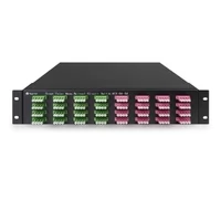
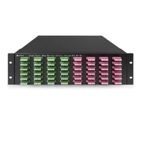
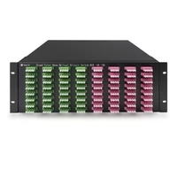
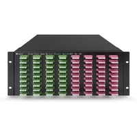
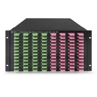
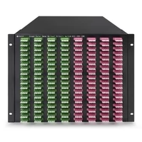
The optical circuit switch (OCS) is rapidly becoming the most important new building block in hyperscale and AI data center architecture. As GPU clusters scale to tens of thousands of accelerators and 800G/1.6T transceivers saturate the spine, traditional electrical packet switches are hitting a hard ceiling on power consumption and latency. The OCS bypasses that ceiling by steering light directly, with no electrical conversion in the data path.
This guide explains what an optical circuit switch is, how 3D MEMS and cascaded matrix architectures differ, why hyperscalers and AI operators are deploying OCS at the heart of their fabrics, and how to evaluate the right OCS technology for your network. We also outline FiberMall’s OCS 3D Matrix Switches and MOS Cascaded Matrix Switches, and the use cases where each delivers the strongest engineering and cost advantages.
What Is an Optical Circuit Switch (OCS)?
An optical circuit switch is a network device that establishes a transparent, end-to-end light path between two ports without converting the optical signal to an electrical signal. In a traditional packet switch, every photon entering an input port is converted to an electrical signal, processed by a switching ASIC and SerDes (Serializer/Deserializer), then converted back to light at the output port. This Optical-Electrical-Optical (O-E-O) cycle costs energy, adds latency, and locks the switch to specific data rates and protocols.
An OCS does none of that. It physically redirects the light beam itself, much like a railway switch redirects a train onto a different track. Once a circuit is established between two ports, photons flow through the device at the speed of light in glass, with no packet inspection, queuing, or buffering.
Because the OCS never reads the data, it is fully transparent to wavelength, modulation format, and bit rate. The same OCS port that carries 100G NRZ traffic today can carry 800G PAM4 or 1.6T DP-16QAM coherent traffic tomorrow with no hardware change.
How OCS Differs from Packet Switching
| Property | Electrical Packet Switch | Optical Circuit Switch |
| Switching domain | Electrical (after O-E-O conversion) | Optical (light beam steering) |
| Granularity | Per-packet | Per-circuit (port pair) |
| Reconfiguration time | Nanoseconds | Milliseconds |
| Data rate awareness | Tied to ASIC generation | Rate and protocol agnostic |
| Power per port | High (driven by ASIC + SerDes) | Very low (passive optics + MEMS control) |
| Best fit | Bursty, statistically multiplexed traffic | Long-lived, high-bandwidth flows (AI training, DCI) |
The takeaway: OCS does not replace packet switching. It complements it. Most modern hyperscale fabrics use OCS for long-lived, high-bandwidth circuits (such as GPU-to-GPU all-reduce traffic) while keeping packet switches for dynamic, bursty traffic like web requests.

How an Optical Circuit Switch Works
The internal mechanism varies by architecture, but every OCS shares three core elements: an input fiber array, a steering element, and an output fiber array.
3D MEMS Beam Steering
3D MEMS (Micro-Electro-Mechanical Systems) is the dominant technology in large-port-count optical circuit switches. Inside the OCS chassis, two arrays of microscopic mirrors (typically a few hundred micrometers across) are arranged on silicon wafers. Each mirror sits on a tiny gimbal that can tilt on two axes under electrostatic control.
When a circuit is requested between input port A and output port B:
- The OCS controller calculates the precise tilt angles required for the mirror at position A and the mirror at position B.
- Voltage is applied to MEMS actuators, tilting both mirrors.
- Light entering port A reflects off mirror A, crosses the free-space optical region inside the chassis, reflects off mirror B, and exits port B.
This is why 3D MEMS scales so well to high port counts. Adding ports means adding more mirrors on the wafer, not adding more switching stages. Modern 3D MEMS OCS systems support 192×192, 320×320, and even larger non-blocking matrices in a single chassis.
Cascaded Optical Matrix
A cascaded optical matrix takes a different approach. Instead of one large free-space region, multiple smaller optical switching stages are connected in series and parallel to build up the total port count. Each stage may use planar lightwave circuits (PLC), liquid crystal optics, or smaller MEMS arrays.
The cascaded approach trades some insertion loss budget for modularity. You can start with an 8×8 or 16×16 matrix and add stages as your fiber count grows. This is ideal for telecom protection switching, optical lab automation, and progressive data center buildouts where the eventual size is not known on day one.
Insertion Loss and Reliability
Both architectures must hit aggressive insertion loss targets, typically under 3 dB end-to-end, to preserve the optical link budget for downstream coherent or high-baud-rate transceivers. High-quality optical circuit switches use closed-loop feedback (optical taps and photodiodes) to continuously monitor and re-trim mirror positions, compensating for thermal drift and mechanical aging.
Why AI Data Centers Need OCS
The shift to optical circuit switching is being driven by three forces that all collide inside the AI data center.
1. The Power Wall
A single 800G electrical packet switch can draw 2,000 watts. At hyperscale, the SerDes alone account for a large share of the power budget. Replacing 20% of an electrical fabric with optical circuit switches can reduce total facility power by up to 15% and switching-fabric power by close to 90%, because there is no ASIC and no SerDes in the OCS data path.
2. The Latency Wall
AI training workloads spend a surprising fraction of wall-clock time in collective operations like all-reduce. Every nanosecond saved per hop multiplies across thousands of GPUs and millions of iterations. OCS adds essentially zero latency in the data plane, since photons simply traverse glass.
3. The Topology Wall
Different AI models prefer different network topologies: ring, torus, fat-tree, dragonfly. With electrical fabrics, the topology is hard-wired into the cabling. With OCS, the topology is defined in software. Reconfiguring an entire training cluster from a fat-tree to a torus can happen in milliseconds through SDN APIs.
This is exactly why Google’s Apollo, Microsoft’s Sirius, and Meta’s optical fabric initiatives have placed optical circuit switching at the core of their next-generation data center designs.

OCS 3D Matrix Switches: Engineering for Scale
The FiberMall OCS 3D Matrix Switch series targets the core of hyperscale AI factories. Three engineering decisions define the line.
High Port Count
Because 3D MEMS uses two-axis mirror tilt, a single chassis supports very high port counts (192×192, 320×320, and beyond) without the cabling complexity of a multi-stage architecture. This collapses what would otherwise be racks of electrical Clos fabric into a single optical layer.
Closed-Loop MEMS Control
Each mirror in the matrix is monitored by a feedback loop that tracks its actual position against the commanded position. Drift caused by temperature, vibration, or aging is corrected automatically. The result is a stable optical path that holds calibration over years of continuous operation.
Protocol and Rate Transparency
The OCS does not see the traffic. A port carrying 400G FR4 today can carry 800G DR8 or 1.6T coherent tomorrow with no hardware change. This protects the capital investment in the OCS chassis even as transceiver technology generations roll forward.
Target Applications
- GPU-to-GPU fabric in AI training clusters where the topology is rebuilt per-job.
- Data Center Interconnect (DCI) links between buildings or campuses where high bandwidth and rate flexibility matter more than per-packet switching.
- Spine-layer reconfiguration in cloud data centers that want to shift bandwidth between regions or services on a sub-second cadence.
MOS Cascaded Matrix Switches: Modularity and Cost
For environments where modularity, density, and cost matter more than maximum port count, the FiberMall MOS Cascaded Matrix Switches deliver a different design point.
Pay-As-You-Grow Architecture
The cascaded matrix lets operators start with a small matrix and add stages as fiber demand grows. Carriers building optical protection layers, labs automating test fiber setups, and enterprises consolidating cross-connects all benefit from this incremental scaling model.
Redundant Path Protection
For telecom backbones, the cascaded architecture maps cleanly onto 1+1 and 1:N protection schemes. When a working path fails, the matrix reroutes traffic to a protect path in milliseconds with no impact on upper-layer protocols.
Low Crosstalk
Optical isolation between cascaded stages keeps adjacent paths from interfering, which is critical when many wavelengths or services share a single matrix.
Target Applications
- Telecom protection switching at the optical transport layer.
- Lab and test automation for optical research, qualification, and burn-in.
- Automated fiber cross-connect (OXC) in enterprise and colocation environments.
- Financial trading networks where reconfiguration at millisecond speed and rate-agnostic transparency add a measurable competitive edge.
Comparing OCS 3D Matrix and MOS Cascaded Matrix
| Feature | OCS 3D Matrix | MOS Cascaded Matrix |
| Core technology | 3D MEMS mirror steering | Cascaded optical path matrix |
| Best fit | Large-scale AI and cloud core | Lab automation, carrier protection |
| Port count | Very high (scalable to 320+) | Modular, medium-high |
| Switching speed | Milliseconds | Milliseconds |
| Transparency | Fully protocol and rate agnostic | Fully protocol and rate agnostic |
| Insertion loss profile | Single-stage, lowest loss | Multi-stage, planned for budget |
| Form factor | Single dense chassis | Modular, expandable |

Integrating OCS Into a Modern Optical Fabric
An optical circuit switch is most valuable when it is wired into the rest of the optical layer with care.
Transceiver Compatibility
The FiberMall OCS 3D Matrix is tested with the company’s 800G OSFP and QSFP-DD optics, including 800G DR8 and 2x400G FR4 modules. Because the OCS is rate-agnostic, the same chassis works with 100G, 200G, 400G, 800G, and forthcoming 1.6T modules without modification.
SDN Control and Automation
Both the OCS and MOS series expose RESTful APIs, SNMP, and CLI interfaces. This lets operations teams orchestrate optical paths from the same SDN controllers that manage IP and Ethernet layers. Dynamic optical path provisioning, where the controller rebuilds the topology in response to traffic patterns, becomes a routine operation rather than a research project.
Wavelength and Fiber Planning
Even though the OCS is wavelength-agnostic, the rest of the network is not. Plan the fiber plant and the wavelength assignments around the OCS so that any input port can be reasonably routed to any output port. Document the optical link budget for the worst-case path through the matrix, and verify that downstream coherent or PAM4 transceivers have margin.
Common OCS Deployment Considerations
Even with strong vendor support, optical circuit switching introduces a few engineering questions worth working through before deployment.
Reconfiguration Time vs Packet Switching
OCS reconfiguration is on the order of milliseconds, which is excellent for topology changes and protection switching, but not suitable for per-packet decisions. Use OCS for long-lived flows. Pair it with electrical packet switches for short, bursty traffic that needs nanosecond-level statistical multiplexing.
Optical Power Budget
Each port pair through the matrix introduces insertion loss. Confirm the end-to-end optical link budget across the worst-case path, including patch cables, connectors, and any DWDM gear. For long-reach links, allow extra margin for connector aging and thermal drift.
Control-Plane Hardening
The OCS control plane becomes part of your critical infrastructure. Treat it like a router control plane: out-of-band management, redundant controllers, version-controlled configuration, and tested rollback procedures.
Failure Mode Behavior
Plan for the failure mode of the matrix itself. With closed-loop feedback and redundant power supplies, modern optical circuit switches are highly reliable, but a controller fault should fail safe (typically by holding the last good circuit configuration). Verify that fail-safe behavior matches your operational model.
Strategic Use Cases for 2026 and Beyond
AI Training Cluster Reconfiguration
Operators can dynamically change the cluster topology to match each model’s communication pattern. A transformer model with heavy all-reduce traffic prefers a torus; a recommendation model may prefer a fat-tree. With OCS, the topology is reconfigured per job, in software.
Automated Fiber Cross-Connect
Manual fiber patch panels are expensive to operate and prone to human error. An optical circuit switch automates this layer, reducing provisioning time from hours to milliseconds and eliminating the most common cause of cabling outages.
High-Frequency Trading and Low-Latency Markets
In financial trading networks, every microsecond matters. The near-zero data-plane latency of OCS, combined with rate transparency, lets trading firms upgrade transceivers to higher speeds without forklifting their switching layer.
Carrier Protection Switching
In telecom backbones, OCS at the optical transport layer enables fast, lossless protection switching across diverse fiber routes, complementing OTN and ROADM systems.
Frequently Asked Questions (FAQ)
What is the main difference between FiberMall’s OCS 3D Matrix and MOS Cascaded Matrix Switches?
The OCS 3D Matrix Switch uses 3D MEMS technology, where mirrors tilt on multiple axes to redirect light. This supports very high port counts (320×320 and beyond) in a single chassis, ideal for the core of AI data centers. The MOS Cascaded Matrix Switch uses a modular, cascaded design optimized for high-density fiber management, lab automation, and telecom protection switching where scalability and cost-effectiveness are paramount.
How does an optical circuit switch reduce power consumption compared to electrical switches?
Traditional electrical switches require O-E-O (Optical-Electrical-Optical) conversion, which consumes significant energy in SerDes and switching ASICs to process packets. An optical circuit switch is protocol-transparent. It steers the physical light beam using MEMS or cascaded matrices without reading the data, bypassing the electrical processing layer. Switching-fabric power drops by up to 90%, and total facility power can fall by roughly 15% when 20% of the fabric is replaced with OCS.
What is the typical switching speed (latency) of an optical circuit switch?
Data-plane latency is near-zero (nanoseconds), since photons simply traverse glass. Reconfiguration speed (the time to move a connection from port A to port B) is in the millisecond range. This makes OCS perfect for topology reconfiguration, protection switching, and long-lived AI flows, but not for per-packet switching like an Ethernet ASIC.
Are optical circuit switches compatible with Software-Defined Networking (SDN)?
Yes. Both the OCS 3D Matrix and MOS series expose RESTful APIs, SNMP, and CLI interfaces, letting network administrators integrate the optical layer into existing SDN orchestration tools for automated path provisioning and dynamic load balancing.
Can an OCS replace my electrical packet switches?
Not entirely. OCS and packet switches are complementary. Use OCS for long-lived, high-bandwidth flows where rate transparency and low power matter most (AI training, DCI, protection). Keep packet switches for short, bursty traffic that benefits from per-packet statistical multiplexing.
Is an OCS protocol- and bit-rate-agnostic?
Yes. Because the optical circuit switch never converts the signal to electrical form, the same chassis can carry 100G NRZ, 400G PAM4, 800G PAM4, or 1.6T coherent traffic with no hardware change. This protects the capital investment as transceiver generations evolve.
What are the main use cases for cascaded optical matrix switches?
Cascaded optical matrix switches excel in lab automation, carrier protection switching, automated fiber cross-connect, and modular data center deployments. The cascaded architecture supports a pay-as-you-grow model that fits operators who do not need maximum port count on day one.
Conclusion: Build the Optical Layer for the Next Decade
The optical circuit switch is no longer a research curiosity. It is now a production-grade component at the heart of hyperscale AI fabrics, telecom protection layers, and automated cross-connect deployments. By steering light directly, an OCS removes the power, latency, and rate-locking constraints that are pushing electrical switches to their limits.
Key takeaways:
- An optical circuit switch establishes transparent, all-optical paths with no O-E-O conversion in the data plane.
- 3D MEMS architectures scale to very high port counts and excel at AI cluster cores; cascaded matrices deliver modular, cost-effective designs for protection and lab automation.
- OCS reduces switching-fabric power by up to 90% and supports any rate or protocol on the same hardware.
- Use OCS for long-lived, high-bandwidth flows; keep packet switches for bursty traffic.
FiberMall designs and manufactures both OCS 3D Matrix Switches and MOS Cascaded Matrix Switches, tested for compatibility with mainstream 400G, 800G, and emerging 1.6T optical transceivers. Whether you are scaling an AI training fabric, modernizing a telecom protection layer, or automating a colocation cross-connect, our networking specialists can help you select the right optical circuit switch for your deployment.
Request a Quote for OCS systems, or Contact Our Networking Experts to architect an optical fabric built for the next decade of growth.
Related Products:
-
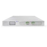
 4×4 MEMS Optical Switch, 1550nm, G.657A2 fiber, LC/APC flange, 1U chassis, single power supply. RJ45/RS232, 220V, with touchscreen.
$5600.00
4×4 MEMS Optical Switch, 1550nm, G.657A2 fiber, LC/APC flange, 1U chassis, single power supply. RJ45/RS232, 220V, with touchscreen.
$5600.00
-
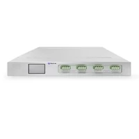
 8×8 MEMS Optical Switch, 1550nm, G.657A2 fiber, LC/APC flange, 1U chassis, single power supply. RJ45/RS232, 220V, with touchscreen.
$7058.00
8×8 MEMS Optical Switch, 1550nm, G.657A2 fiber, LC/APC flange, 1U chassis, single power supply. RJ45/RS232, 220V, with touchscreen.
$7058.00
-
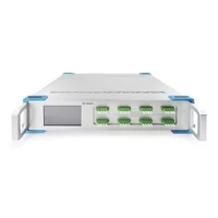
 16×16 MEMS Optical Switch, 1550nm, G.657A2 fiber, LC/APC flange, 2U chassis, single power supply. RJ45/RS232, 220V, with touchscreen.
$12700.00
16×16 MEMS Optical Switch, 1550nm, G.657A2 fiber, LC/APC flange, 2U chassis, single power supply. RJ45/RS232, 220V, with touchscreen.
$12700.00
-
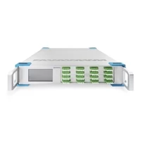
 32×32 MEMS Optical Switch, 1550nm, G.657A2 fiber, LC/APC flange, 2U chassis, single power supply. RJ45/RS232, 220V, with touchscreen.
$38820.00
32×32 MEMS Optical Switch, 1550nm, G.657A2 fiber, LC/APC flange, 2U chassis, single power supply. RJ45/RS232, 220V, with touchscreen.
$38820.00
-
 64×64 3D MEMS Optical Circuit Switches, 1550nm, G.657A2 fiber, LC/APC flange, 2U chassis, single power supply. RJ45/RS232, 220V.
$127000.00
64×64 3D MEMS Optical Circuit Switches, 1550nm, G.657A2 fiber, LC/APC flange, 2U chassis, single power supply. RJ45/RS232, 220V.
$127000.00
-
 96×96 3D MEMS Optical Circuit Switches, 1550nm, G.657A2 fiber, LC/APC flange, 3U chassis, single power supply. RJ45/RS232, 220V.
$203200.00
96×96 3D MEMS Optical Circuit Switches, 1550nm, G.657A2 fiber, LC/APC flange, 3U chassis, single power supply. RJ45/RS232, 220V.
$203200.00
-
 128×128 3D MEMS Optical Circuit Switches, 1550nm, G.657A2 fiber, LC/APC flange, 4U chassis, single power supply. RJ45/RS232, 220V.
$271000.00
128×128 3D MEMS Optical Circuit Switches, 1550nm, G.657A2 fiber, LC/APC flange, 4U chassis, single power supply. RJ45/RS232, 220V.
$271000.00
-
 144×144 3D MEMS Optical Circuit Switches, 1550nm, G.657A2 fiber, LC/APC flange, 4.5U chassis, single power supply. RJ45/RS232, 220V.
$305500.00
144×144 3D MEMS Optical Circuit Switches, 1550nm, G.657A2 fiber, LC/APC flange, 4.5U chassis, single power supply. RJ45/RS232, 220V.
$305500.00
-
 192×192 3D MEMS Optical Circuit Switches, 1550nm, G.657A2 fiber, LC/APC flange, 6U chassis, single power supply. RJ45/RS232, 220V.
$407650.00
192×192 3D MEMS Optical Circuit Switches, 1550nm, G.657A2 fiber, LC/APC flange, 6U chassis, single power supply. RJ45/RS232, 220V.
$407650.00
-
 288×288 3D MEMS Optical Circuit Switches, 1550nm, G.657A2 fiber, LC/APC flange, 9U chassis, single power supply. RJ45/RS232, 220V.
$608820.00
288×288 3D MEMS Optical Circuit Switches, 1550nm, G.657A2 fiber, LC/APC flange, 9U chassis, single power supply. RJ45/RS232, 220V.
$608820.00