Optical modules are distinct from one another in their transmission distance, a feature that should be taken into account in addition to other specifications like data rate when selecting fiber optic transceivers. In the era of high-speed networks, the continuous progress of optical fiber transmission technology requires further distance in optical network communication. Some users may be ambivalent about the measurement of an optical module’s transmission distance in practice. If you are one of them, find out the methods in this article now!
1. Working Wavelength
Checking out the working wavelength and optical fiber mode of an optical module is one of the common ways to estimate how long an optical transceiver can reach. If the optical module works at a wavelength near 850nm (880nm) or 910nm (940nm), then the module is a multi-mode fiber(MMF) optical transceiver, and if the working wavelength is 1310nm or 1550nm, it is a single-mode fiber(SMF)optical module. Generally, the maximum transmission distance(generally no more than 500 m) supported by a multi-mode fiber optical module is much shorter than that of a single-mode fiber optical module.
2. Fiber Optic Cable Type
Apart from working wavelength, the type of multimode fiber is another factor that makes a difference in the transmission distance. For instance, the shortest link length for multimode fiber cables such as OM3, OM4, and OM5 based on 40G is 2m (the same as the 100G)and the longest is 240m, 350m, and 440m respectively. While OM3, OM4, and OM5 work on 100G, their max transmission distances extend to 75m, 100m, and 150m individually due to OM4 and OM5 fiber cables’ optimized modal dispersion and their increased bandwidth distance product.
For single-mode fiber optical modules, when the data rate is less than 10G, their supporting transmission maximum distance is not as long as that of those at 1550 wavelength theoretically due to the signal loss. If the data speed is more than 10G, the dispersion may be limited, so that the optical transceiver at 1310 wavelength may be able to support a longer transmission distance.
However, all the above factors can not make a difference simply because lasers such as EML or DML also affect transmission distance. There tends to be laser chirping in DML. Laser chirping can lead to significant dispersion effects for intensity-modulated pulses, which limits the transmission in return. When the speed reaches 25Gbps/s, the dispersion in C-band transmission of 20km single-mode fiber cable is relatively large.
3. Compliant Protocols & Standards
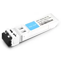
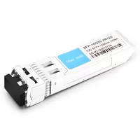
Apart from checking the operating wavelength of optical modules, the protocol and standard are other methods to measure the signal transmission distance. The figure below shows a series of different 10G SFP+ fiber optic modules.

◮ Different Types of 10G SFP+ Fiber Optic Transceivers
What do the letters such as SR and LR stand for? You may understand the relationship between their meanings and their link lengths after getting the answer. SR = short reach, LR= long reach, LRM = long reach multimode, ER = extended reach, ZR = the (Z) best reach. In addition to the IEEE, there are other specifications and standards issued by organizations like MSA and OIF. Please check out the following fiber optic distance charts for more information.
|
PMD Standard |
Typical Transmission Distance |
Explanation |
|
KR |
dozens of meter |
backplane connection |
|
CR |
a few meters |
bronze bearing |
|
SR |
hundreds of meters |
mostly multi-mode |
|
LRM |
220m |
long reach multimode |
|
DR |
500m |
Parallel Single Mode(PSM) |
|
FR |
2km |
100G CWDM4 |
|
LR |
10km |
Long reach single-mode |
|
ER |
40km |
Extended long reach |
|
ZR |
80km |
more extended long reach |
|
ZR+ |
500km |
ZR Extension of the (Z) best reach VS 400G ZR |

◮The label on the optical transceiver QSFP28 100G LR4
What matters the most on the optical transceiver label is the information like QSFP28-100G-LR4, i.e. what is the nomenclature for it? Take QSFP28-100G-LR4 as an example, the part “QSFP28” refers to the form factor of the module, and the most common form factors include SFP, CFP, and QSFP; the middle part “100G” represents the fiber optic module’s fundamental data transmission rate such as 10G, 100G, and 400G; “LR” stands for its supported PMD(Physical Medium Dependent) standard; the number “4” indicates that the optical module has four signal channels.
Not all optical transceiver’s supported link lengths will be given on the label. By checking out the table above, you may still easily get knowledge of its application and transmission distance.
4. Receiver Sensitivity
Before you get more details on how to measure the transmission distance, it is necessary to have a basic understanding of transiting optical power. The transiting optical power can be regarded as the intensity of the light, in W or MW, or dBm( W or mW is a linear unit and dBm is a logarithmic unit), which is usually measured by optical power meters. dBm is the most frequently-used unit to represent optical power. The equation can be expressed as
P(dBm)=10Log(P/1mW)
Optical power attenuating by half mW is tantamount to reducing by 3dB. 0dBm of optical power corresponds to 1mW. The optical power of PON series products has to be measured by an exclusive optical power meter due to their burst mode ONU end. In this case, the optical power meters needs to be connected in series within the circuits to get an instant uplink and downlink optical power result.


◮ Optical Power Meters
Optical communication systems use a BER value to specify the performance requirement for a particular transmission link application. Defining the receiver sensitivity of an optical transceiver is actually measuring an optical power budget in dBm incident on the photodetector. This is a pretty useful method in lower data rate optical module systems for dispersion and chirping are not the main factors to transmission link length. The measuring method is as follows:
P budget = Min Pt – Min Pr
Why there is a minimum power for transiting and a minimum sensitivity for a photodetector? The performance of optical modules is often not consistent with each other throughout the production and is changing over the life cycle. Therefore, the worst performance needs to be considered when calculating the average power. This is different from academic research pursuing the approval of authority; products are measured by their usability and general applicability.
Based on the power budget, the maximum supported transmission distance can be measured by the optical fiber loss in bands of 1310nm and 1550nm. In general, the average loss of the O band and C band is measured by 0.35 dBm and 0.25 dBm respectively. For example, if an SMF optical module’s working wavelength is 1310nm; its transiting power is -4~0dBm, and its receiver sensitivity is -22dBm. Thus it supports a transmission distance of about 50km, corresponding to the ER standard according to the above calculation method.
But this method does not take factors like system margin, optical fiber connector, loss, and dispersion of optical fiber connector into account. Therefore, this calculated result is just the theoretical maximum distance, but its actual result is a little bit less than that.
5. Required OSNR
For fiber optic transceivers with long transmission reach, OSNR(Optical Signal-to-Noise Ratio) is another important indicator apart from the receiver sensitivity. As for optical transceivers with the short reach mentioned above, since there is no OA(Optical Amplifier) in the optical fiber transmission links, optical power is the major dominating indicator to test module system performance. When the signal is transmitted over a multi-span network, the power of the link system can be improved by OA. Therefore, it is not accurate to measure the transmission distance only by optical signal power, and the signal-to-noise power of optical links must be considered as well. The following figures show a typical WDM transiting system and optical link with a long distance.

◮Typical WDM Optical Fiber Link & Communication System
There are booster amplifiers and pre-amplifier on both the transmitter end and receiver end. An inline amplifier to remedy the losses from each span of an optical fiber. For instance, if the input power in a single-wavelength link is Pin dB, there are N optical fiber spans with an average loss of Aspan dB and the length is Lspan km, the minimum OSNR is ReOSNR dB as long with Penalty dB link transmission after the system is tested for no BER. In this case, the required system margin is budget dB.
Each EDFA has the same OSNR,i.e.NF dB so that the OSNR of the single-wavelength signal at the receiver end can be roughly defined by the following equation
OSNRest = Pin + 58 -NF -10log10(N)-Aspan
According to the requirement of the optical fiber system, the maximum transmission distance cannot be achieved unless the following condition is provided,
OSNRest≥ReOSNR+Penalty+Budget
Combined with the above 2 equations, the biggest number of the span can be calculated so that the maximum transmission distance can be expressed as
Lmax = N*Lipan
Generally, 100G coherent system’s pin is about 1dBm. For EDFA optical link in practice, its NF is 5~7dB with Lsapn =80 or 100km;
while common single-mode fiber’s average span is 22dB(100km) and its power budget is 5dB. At present, the typical required OSNR for a commercial grade 100G optical transceiver can reach within 11dBm and it is easy to achieve a transmission distance of over 2000km.
When there is a booster amplifier at the transmitter end and a pre-amplifier at the receiver end, the calculated maximum number of spans should minus 1. In this case, the maximum transmission link length can be measured correctly. In reality, a number of signal impairments that are inherent in optical fiber transmission systems can degrade the link performance.
The penalties within an optical fiber transmission system include the link filter’s penalty, nonlinear effects that arise when there is a high optical power level in a fiber link, and a penalty from the optical module’s operation. Also, power penalties are from signal impairment triggered by the link’s dynamic input(usually the Polarization Dependent affected by changes in environment temperature, vibration, and press, such as rapid SOP variation) and the degrading performance caused by the burn-in components.
Though an overall estimation of an appropriate system margin is not easy, it is essential to the high-efficiency optical fiber communication link system in the future. As most of the upgraded performance, for example, the upgraded performance for DSP through nonlinear effect remedy is 0.5dB, would be likely to be counteracted by the too convectional system margin.
When all the techniques have been tried, it may be high time that people pay attention to how to reasonably set the system OSNR margin, through which some capacity or distances may be enhanced.
Conclusion
According to the above analyses, the optical transmission distance is affected by various factors including working wavelength, the optical fiber mode, compliant protocols & standards, receiver sensitivity, and required OSNR. An optic fiber transceiver‘s transmission distance will be easily measured or estimated when you take these factors into account.
Related Products:
-
 QSFP28-100G-ZR4 100G QSFP28 ZR4 1296-1309nm LWDM 80km LC SMF DDM Transceiver Module
$1500.00
QSFP28-100G-ZR4 100G QSFP28 ZR4 1296-1309nm LWDM 80km LC SMF DDM Transceiver Module
$1500.00
-
QSFPP-40G-ER4 40G QSFP+ ER4 1310nm (CWDM4) 40km LC SMF DDM Transceiver Module
$449.00
-
Cisco SFP-25G-ER40-S Compatible 25G SFP28 ER 1310nm 40km LC SMF DDM Transceiver Module
$125.00
-
SFP-10G55-ZR 10G SFP+ ZR 1550nm 80km LC SMF DDM Transceiver Module
$150.00
-
SFP-10G55-ZR100 10G SFP+ ZR 1550nm 100km LC SMF DDM Transceiver Module
$280.00
-
SFP-10G55-ZR120 10G SFP+ ZR 1550nm 120km LC SMF DDM Transceiver Module
$400.00