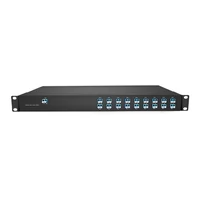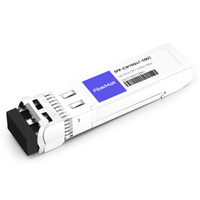

The number on the CWDM SFP label is not the number on the mux port.
A module arrives marked 1470 nm. The port it needs to reach is labeled CH11. Neither label mentions the other, and nothing in the box explains that they describe the same channel. That single gap accounts for a large share of CWDM links that come up dark on a first attempt that looked correct on paper.
If you have bought colored optics before, you already know the wavelength matters. What usually goes wrong is the translation step between the catalog and the rack.
This guide closes that gap. You’ll get the full channel-to-wavelength table, reach options for 1.25G, 10G, and 25G, the practical limits of CWDM transmission and amplification, and the pairing and spares rules that help prevent repeat failures. If you just need the channel decoder, browse the CWDM SFP catalog alongside the table below.
What Is a CWDM SFP?
A CWDM SFP, often listed as a CWDM optical module, is a hot-pluggable transceiver designed for a specific wavelength on the 20 nm coarse wavelength division multiplexing (CWDM) grid. In a conventional duplex CWDM link, each module operates on its assigned channel wavelength, so both ends must use compatible wavelengths. A mux or demux then routes each wavelength to its corresponding port.
The form factor is SFP, SFP+, or SFP28. The key difference is the optical specification: a CWDM transmitter is designed for a specific wavelength on the CWDM grid, while a conventional grey optic is designed for a standard wavelength band, such as the 1310 nm or 1550 nm region. Their wavelength tolerances and intended optical interfaces are not necessarily interchangeable.
That’s why the industry often calls them colored optics. Some vendors also use color-coded latches or pull tabs to help identify wavelengths, although color schemes are not universal. A clear wavelength label is still the most reliable way to identify a module.
Grey optics are not automatically interchangeable just because they have the same data rate and reach; wavelength, fiber type, interface standard, link budget, and host compatibility must also match. In a conventional duplex CWDM link, the modules at both ends must use the same CWDM channel wavelength. The trade-off is reduced wavelength flexibility in exchange for carrying multiple channels over the same fiber pair, with up to 18 channels available on the standard grid.
The optical transceiver guide covers the general anatomy if you want the basics first. The CWDM complete guide explains the system around the module.
The Wavelength Grid and Channel Numbers
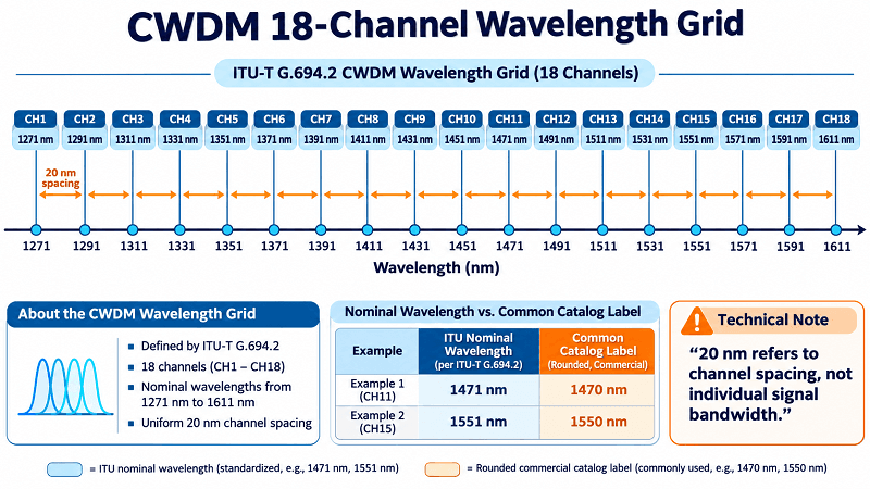
ITU-T G.694.2 sets 18 nominal wavelengths from 1271 to 1611 nm at 20 nm spacing. The standard defines wavelengths, not channel numbers. The 1-to-18 numbering is vendor convention, but it’s near-universal, and it’s what appears on mux port labels.
| Ch | Nominal | Catalog label | Ch | Nominal | Catalog label |
| 1 | 1271 nm | 1270 nm | 10 | 1451 nm | 1450 nm |
| 2 | 1291 nm | 1290 nm | 11 | 1471 nm | 1470 nm |
| 3 | 1311 nm | 1310 nm | 12 | 1491 nm | 1490 nm |
| 4 | 1331 nm | 1330 nm | 13 | 1511 nm | 1510 nm |
| 5 | 1351 nm | 1350 nm | 14 | 1531 nm | 1530 nm |
| 6 | 1371 nm | 1370 nm | 15 | 1551 nm | 1550 nm |
| 7 | 1391 nm | 1390 nm | 16 | 1571 nm | 1570 nm |
| 8 | 1411 nm | 1410 nm | 17 | 1591 nm | 1590 nm |
| 9 | 1431 nm | 1430 nm | 18 | 1611 nm | 1610 nm |
Print it, tape it inside the splice enclosure, and half your field calls disappear.
Why 1270 and 1271 Refer to the Same CWDM Channel
The ITU grid specifies a nominal center wavelength of 1271 nm for channel 1. Some catalogs use 1270 nm as a rounded product label. Treat 1270 nm as a catalog designation for channel 1, not as a separate wavelength on the ITU grid.
The pattern holds across the whole grid: 1471 becomes 1470, 1551 becomes 1550, 1611 becomes 1610. A vendor who writes 1470 nm is describing channel 11, not a wavelength two nanometers away.
This matters most at channel 3. The grid wavelength is 1311 nm, while the catalog label is often 1310 nm. That label is also commonly used for grey optics operating in the 1310 nm region. The similar labels can cause confusion, but they do not establish optical compatibility: the transmitter wavelength tolerance and the mux filter passband must be checked.
Nadia, a NOC engineer in Amman, encountered the CH11 version of this problem in March 2025. Her team ordered twelve 1470 nm SFPs for a six-site metro build. The muxes arrived labeled CH11, CH12, and so on. A junior technician patched the first site, saw no light, and logged the module as dead on arrival (DOA).
The modules were fine. The port was fine. The label was the problem. Forty minutes and one phone call later, the link came up, and Nadia had a laminated card taped inside every enclosure on the project.
CWDM SFP Data Rates and Reach Tiers
Reach depends on rate more than on anything else. The same fiber and the same grid support very different distances at 1.25G, 10G, and 25G.
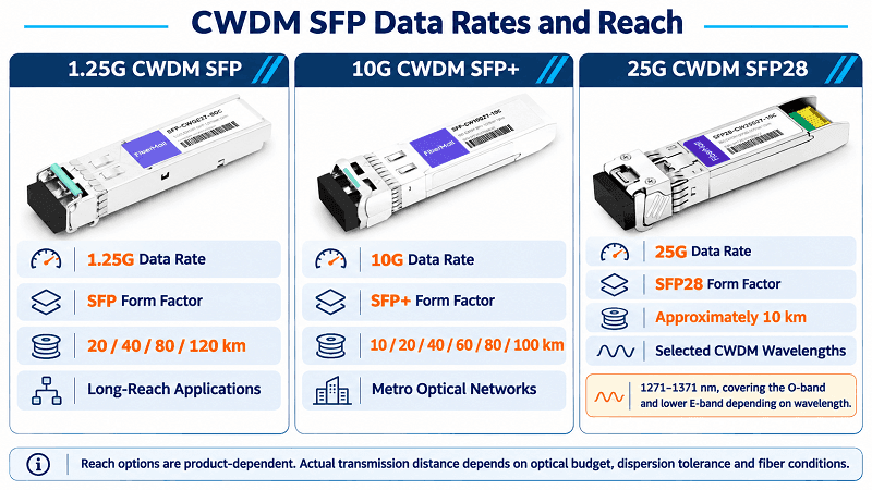
1.25G: 40, 80, and 120 km
Gigabit CWDM SFPs are commonly used for longer-reach links. FiberMall stocks 20, 40, 80, and 120 km versions, with the 120 km model priced higher than the 80 km version.
At 1.25G, chromatic dispersion is generally less restrictive than it is at higher data rates, but it should not be ignored. Some modules are specified for reaches of up to 120 km over G.652 fiber; that distance is not guaranteed for every module or link. Check the transmitter and receiver specifications, fiber attenuation, connector and splice losses, and dispersion tolerance before deployment. If your requirement is to extend a Gigabit link over a long distance, a suitable 1.25G CWDM SFP can be a cost-effective option.
10G: 10, 20, 40, 60, 80, and 100 km
Ten-gigabit CWDM SFP+ modules are available in reach options including 10, 20, 40, 60, 80, and 100 km. The 80 km option is common, but longer reaches require careful consideration of both optical loss and chromatic dispersion.
A typical 10G 80 km module may specify a transmit-power range of 0 to +4.0 dBm and receiver sensitivity around -23.0 dBm. This corresponds to a nominal optical budget of 23 to 27 dB across the stated transmitter range, before accounting for engineering margin and receiver overload limits. For a conservative design, calculate the available budget using the guaranteed minimum transmit power and the specified receiver sensitivity; do not assume that a typical or maximum transmit-power value will always be available.
25G: 10 km across selected CWDM wavelengths
Twenty-five-gigabit CWDM SFP28 modules are a different category. Some designs use selected CWDM wavelengths from 1271 to 1371 nm, covering the O-band and the lower E-band, and are commonly specified for reaches of about 10 km. The exact wavelength options and reach depend on the module.
That profile can suit 5G fronthaul deployments with short spans, multiple endpoints, and a fiber pair serving several radio units. O-band wavelengths are often selected because chromatic dispersion is relatively low in this region. However, the exact reach depends on the selected wavelength, transceiver design, fiber characteristics, and link budget.
Why 10G CWDM Reach Is Often Limited to 80–100 km
Both optical loss and chromatic dispersion can limit reach.
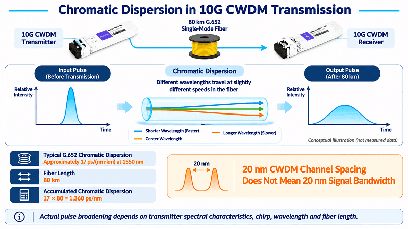
A typical G.652 fiber has a chromatic-dispersion coefficient of approximately 17 ps/(nm·km) around 1550 nm. This value describes the wavelength dependence of propagation delay; it is not determined by the 20 nm spacing between adjacent CWDM channels. The actual pulse broadening depends on the signal’s spectral characteristics, the transmitter’s chirp, the operating wavelength, and the fiber length. CWDM filter passband and transmitter wavelength tolerance are separate design considerations.
At 1550 nm, 80 km of fiber with a dispersion coefficient of 17 ps/(nm·km) produces approximately 1,360 ps/nm of accumulated chromatic dispersion. Whether a 10G link can tolerate that amount depends on the transmitter and receiver design and the module’s specified dispersion tolerance. Some CWDM SFP+ products are rated for 80 to 100 km, but these ratings are product-specific. Do not extrapolate a 1.25G reach rating to 10G; any longer-reach 10G design must be supported by its own validated transceiver specification and link budget.
Tom, an ISP engineer in Yorkshire, learned this in the least convenient way. A customer site 118 km away needed 10G. His supplier quoted a 120 km CWDM solution based on a 1.25G product in the catalog, assuming that the reach rating would carry over to 10G.
The link operated at 1.25 Gb/s but could not maintain error-free 10 Gb/s operation over the same span. The fix was a regenerator at an intermediate hut, which added cost and an additional failure point that nobody had budgeted for. The lesson is simple: a 120 km rating for a 1.25G module cannot be applied to a 10G module. Each data rate requires its own validated reach specification.
Why Standard C-Band EDFAs Cannot Amplify All CWDM Channels
The second planning constraint is optical amplification.
A conventional C-band erbium-doped fiber amplifier (EDFA) typically operates over approximately 1530 to 1565 nm. Of the 18 nominal CWDM wavelengths, two fall within this range: channel 14 at 1531 nm and channel 15 at 1551 nm. The other 16 channels are outside the typical C-band range and therefore are not amplified by a conventional C-band EDFA.
This is one reason DWDM is commonly used for long-haul transmission: many DWDM channels can be placed within an amplifier’s operating band, allowing a compatible EDFA to amplify multiple channels at once. The CWDM grid spreads its 18 channels across a much wider wavelength range, so a conventional C-band EDFA covers only a small part of the grid. Other approaches, including Raman or semiconductor optical amplifiers, may be used in appropriately designed CWDM systems, but they require system-level engineering.
Planning a long span? Send us the route length, splice count, and data rate, and we’ll help assess whether the link budget closes or whether regeneration or another transport design is needed. Request a link budget review.
Pair Matching and Compatibility
Three rules cover almost every CWDM SFP order.
Same channel wavelength at both ends for a conventional duplex link. A 1471 nm CWDM module should be paired with a compatible 1471 nm module at the far end—not a 1491 nm or 1451 nm module. The mux handles wavelength routing; the transceivers must match the assigned channel at each end. BiDi configurations are different and may use complementary transmit and receive wavelengths, so always follow the specific product specification.
Reach ratings may differ at the two ends. For example, a 40 km module and an 80 km module may work together if both directional link budgets meet the receiver requirements and remain within the permitted input-power range. Check each direction separately; the lower-rated module does not automatically define every aspect of the link. Mixing reach ratings can also complicate spares management, so many operators standardize where practical.
Check transceiver coding and host-platform compatibility. Modules may be programmed for Cisco, Juniper, Arista, HPE, Huawei, or MSA-compatible platforms. Depending on the switch, an unsupported or incorrectly coded module may be rejected, flagged with a warning, or operate with limited support. Also confirm that the switch port supports the module’s form factor, data rate, and optical interface; compatibility requirements vary by platform. For a port overview, see the SFP and QSFP ports guide.
Some colored SFPs use wavelength-coded latches or pull tabs, but the color scheme varies by vendor. Do not rely on color alone, especially after years in a hot cabinet, when plastic may fade and labels may peel. Always verify the wavelength printed on the module.
Digital diagnostics are useful once the link is up. If the CWDM SFP supports DDM, it can report parameters such as transmit power, receive power, temperature, and supply voltage. If one channel’s receive power is 3 dB lower than expected, you can investigate that path before opening the enclosure. Available diagnostic parameters depend on the module.
Grey 1310 vs CWDM Channel 3
This is the most expensive confusion in CWDM, and it’s built into the naming.
A conventional 1310 nm grey optic is designed for a standard 1310 nm operating region, but its actual transmitter spectrum is not a 20 nm-wide signal. Its center wavelength, spectral width, and wavelength tolerance are defined by the relevant module specification. It must also match the far-end optic’s interface and operating requirements.
Channel 3 has a nominal CWDM center wavelength of 1311 nm. It is intended to pass through the corresponding CWDM mux/demux channel port, whose filter passband is designed for that channel.
Do not assume that a grey 1310 nm module will work through a CWDM Channel 3 port. Compatibility depends on the module’s wavelength tolerance and spectral characteristics, as well as the mux filter’s passband. A link that appears to work under one set of conditions may not have sufficient operating margin across temperature and other variations.
An intermittent link is particularly difficult to troubleshoot: it may pass an acceptance test under one set of environmental conditions and fail when temperature or other operating conditions change.
The practical rule is to connect a grey optic to a compatible 1310 nm wideband or window port—not to assume that it is compatible with a CWDM channel port. If the mux has no suitable window port, use a separate fiber path or a CWDM transceiver specified for the required channel.
The CWDM mux/demux guide explains window ports and channel routing in more detail.
CWDM4 Is Not Transport CWDM
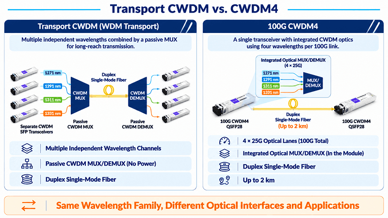
CWDM4 uses four wavelengths: 1271, 1291, 1311, and 1331 nm. Those are CWDM channels 1 through 4, which makes the name look like a subset.
It isn’t. CWDM4 is a 100G data-center optical interface that carries four 25G optical lanes over a duplex single-mode fiber pair, typically supporting a reach of up to 2 km. It is commonly implemented in a single QSFP28 transceiver with integrated optical multiplexing and demultiplexing, not as four separate SFPs feeding a passive transport CWDM mux.
If you’re specifying a data-center 100G link, CWDM4 is the right search. If you’re building a transport link across a campus, you want individual CWDM SFPs and a passive mux. Same wavelengths, different product, different reach.
Link Budget With Real Numbers
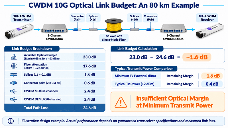
Here’s an illustrative calculation for an 80 km 10G span, using the stated specifications of a 1470 nm CWDM module and a representative loss budget. Actual values must be checked against the exact transceiver and mux/demux datasheets.
| Item | Value |
| Minimum transmit power | 0 dBm |
| Receiver sensitivity | -23.0 dBm |
| Available optical budget | 23.0 dB |
| Fiber, 80 km at 0.22 dB/km | 17.6 dB |
| Splices, 16 at 0.1 dB each | 1.6 dB |
| Connector pairs, 2 at 0.3 dB each | 0.6 dB |
| CWDM mux, 8-channel | 2.4 dB |
| CWDM demux, 8-channel | 2.4 dB |
| Total path loss | 24.6 dB |
| Remaining margin (available budget − path loss) | -1.6 dB |
At the guaranteed minimum transmit power, this link does not close: the calculated path loss exceeds the available optical budget by 1.6 dB. This is exactly why the link budget should be checked before ordering.
Even if a particular module operates at a typical transmit power of +2 dBm, the remaining margin would be only 0.4 dB. That is not sufficient for a robust design and does not replace a calculation based on guaranteed specifications. Reducing splice and connector losses can help, but the design must still include an appropriate engineering margin.
The practical conclusion is that this example does not support an 80 km link at the stated minimum transmit power. Whether another 80 km 10G CWDM configuration will work depends on its actual optical specifications and measured path loss. Use real component values and an appropriate design margin, not the headline reach alone.
How to Choose a CWDM SFP
- Pick the channel from the mux port, not the catalog. Read the port label, convert it with the table, then order.
- Match the transceiver to the switch port. Confirm that the port supports the required form factor, data rate, and optical standard. Some SFP28 ports support 10G SFP+ modules, but this is platform-dependent; do not assume cross-compatibility.
- Choose reach from the link budget, not distance alone. Calculate fiber attenuation using the actual route length and wavelength, then add connector, splice, mux/demux, and other component losses. Include an appropriate engineering margin.
- Confirm the coding. Cisco, Juniper, Arista, HPE, Huawei, or generic.
- Check the temperature grade. Many commercial modules are specified for 0 to 70 °C, while industrial-temperature options cover wider operating ranges. Outside plant and unheated cabinets may require industrial-grade modules; verify the actual operating environment.
- Stock spares for each active wavelength and data-rate combination. Do not rely on a generic spare that may use the wrong channel.
That last point deserves its own section.
Spares and Labelling
A spare CWDM SFP only helps if it’s the right channel. Five spare modules covering five channels you don’t use is five modules of inventory and zero modules of protection.
Hiroshi, a utility network engineer in Osaka, found this out during a 2024 storm season. A 1551 nm module failed on a protection path. The spares bin held six CWDM SFPs, all 1471 nm, all bought as “spares” when the project started.
The path stayed down for two days waiting on a courier. The inventory was worth about $200 and prevented nothing.
The fix is simple: stock spares for each active wavelength and data-rate combination used in the network, with quantities based on service criticality and replacement lead time. Label the bin by wavelength and data rate, not just by part number. Label the mux ports the same way so the inventory and field equipment are easy to match.
FAQ
What is a CWDM SFP?
A CWDM SFP is an optical transceiver designed for a specific wavelength on the 20 nm CWDM grid, which defines 18 nominal wavelengths from 1271 to 1611 nm. It is available in different form factors and data rates, and must be compatible with the host port and the optical interface at the far end. In a conventional duplex link, both ends use the same CWDM channel wavelength.
What is the difference between a CWDM SFP and a grey SFP?
A grey SFP operates at a standard nominal wavelength, such as 1310 or 1550 nm, while a CWDM SFP is designed for a specific wavelength on the CWDM grid. Neither type is automatically interchangeable: both ends must match in wavelength, data rate, optical interface, fiber type, and link budget. CWDM enables multiple wavelength channels to share a fiber pair through a suitable mux/demux system.
Do both ends need the same wavelength?
For a conventional duplex CWDM link, both ends use the same channel wavelength. For example, a 1471 nm module should be paired with a compatible 1471 nm module. Reach ratings may differ if both directional link budgets meet the required specifications. BiDi products may use complementary transmit and receive wavelengths, so follow the product-specific pairing requirements.
What does CH11 mean on a mux port?
Channel 11, which is 1471 nm on the ITU grid and usually listed as 1470 nm in catalogs. The channel number and the wavelength describe the same thing in two different notations.
Can I use a 1310 nm grey SFP in a CWDM mux?
Only if the mux provides a compatible 1310 nm wideband or window port. Do not assume that a conventional grey 1310 nm module is compatible with the 1311 nm Channel 3 filter port. Compatibility depends on the module’s wavelength tolerance and the mux filter passband; verify both specifications before deployment.
What is the maximum distance for a CWDM SFP?
There is no single maximum distance for every CWDM SFP. Depending on the product, some 1.25G modules support up to 120 km, 10G modules commonly offer reach options up to 80–100 km, and some 25G CWDM SFP28 modules support around 10 km. Actual reach depends on the transceiver specifications, wavelength, fiber, total path loss, dispersion tolerance, and system design. Conventional C-band EDFAs cover only two of the 18 nominal CWDM channels, but other amplification approaches may be possible.
Is CWDM4 the same as CWDM?
No. CWDM4 is a 100G data-center optical interface that uses four wavelengths over a duplex single-mode fiber pair for reaches of up to about 2 km, typically in a QSFP28 transceiver. Transport CWDM uses separate wavelength-specific transceivers and a passive mux/demux to carry multiple channels over longer fiber links.
The Short Version
Order by channel, not by wavelength label. Convert with the table, confirm the coding, and check the budget before you check the price.
Reach depends on the transceiver design and the complete link budget. Some 1.25G modules support up to 120 km, while 10G CWDM SFP+ products commonly offer up to 80–100 km and 25G CWDM SFP28 products often target shorter links. Chromatic dispersion and optical loss both matter; the 20 nm CWDM channel spacing is not the signal bandwidth. Conventional C-band EDFAs amplify only two nominal CWDM channels, although other amplification technologies can be considered in a properly engineered system.
FiberMall offers CWDM SFP modules at 1.25G, CWDM SFP+ modules at 10G, and CWDM SFP28 modules at 25G, with coding options for major switch vendors. The 10G 80 km 1470 nm CWDM SFP+ is one option for metro links, subject to a verified link budget. If you’d like to confirm the channel plan first, send us the port list and we’ll map it to suitable part numbers.
The grid itself hasn’t changed since ITU-T G.694.2 fixed it, and neither has the CWDM SFP that sits on it. The labels on the boxes still don’t match the labels on the ports. Now you know why.
Related Products:
-
 Passive CWDM Double Fiber Mux & Demux Module 18 CH (1270-1610nm) LC/UPC 1U Rack
$630.00
-
Passive CWDM Double Fiber Mux & Demux Module 16 CH (1310-1610nm) 1U Rack
$570.00
-
CWDM MUX 8CH 16 Wavelengths (TX: 1310/1330/1390/1410/1470/1490/1550/1570nm RX: 1350/1370/1430/1450/1510/1530/1590/1610nm) LC/UPC Single Fiber 1U Rack
$320.00
-
Passive CWDM Double Fiber Mux & Demux Module 8CH (1470-1610nm) LC/UPC LGX BOX
$280.00
-
CWDM MUX 4CH 8 Wavelengths (TX: 1470/1490/1510/1530nm RX: 1550/1570/1590/1610nm) with Express Port LC/UPC Single Fiber LGX BOX
$150.00
-
Passive CWDM Double Fiber Mux & Demux Module 4 CH (1470-1530nm) LC/UPC LGX BOX
$150.00
-
Passive CWDM Single Fiber 1 Channel OADM LGX BOX
$70.00
-
Passive CWDM Double Fiber 2 Channels OADM LGX BOX
$130.00
-
Passive CWDM Double Fiber 4 Channels OADM LGX BOX
$250.00
-
SFP-CW10G27-40C 10G CWDM SFP+ 1270nm 40km LC SMF DDM Transceiver Module
$95.00
-
SFP-CW10G27-10C 10G CWDM SFP+ 1270nm 10km LC SMF DDM Transceiver Module
$60.00
-
SFP-CW10G59-05C 10G CWDM SFP+ 1590nm 5km LC SMF DDM Transceiver Module
$60.00
-
SFP-CW10G27-20C 10G CWDM SFP+ 1270nm 20km LC SMF DDM Transceiver Module
$75.00
-
SFP-CW10G47-100C 10G CWDM SFP+ 1470nm 100km LC SMF DDM Transceiver Module
$280.00