
The working principle of switches
- The switch establishes the mapping between the source MAC address and the switch port according to the received data frame and writes it into the MAC address table.
- The switch compares the destination MAC address in the data frame with the established MAC address table to decide which port will forward it.
- If the destination MAC address in the frame is not in the MAC address table, it is forwarded to all ports. This process is called flood.
- Broadcast frames and multicast frames are forwarded to all ports.
The three main functions of switches
Learning: The Ethernet switch learns the MAC address of each port-connected device and maps the address to the corresponding port in the MAC address table in the switch cache.
Forwarding/Filtering: When the destination address of a data frame is mapped in the MAC address table, it is forwarded to the port of the connected destination node instead of to all ports (or to all ports if the data frame is a broadcast/multicast frame).
Loop elimination: When a switch includes a redundant loop, the Ethernet switch avoids the creation of loops through the Spanning Tree protocol, while allowing the existence of a backup routine.
Operating characteristics of switches
- Each port of the switch is connected to a segment that is an independent conflict domain.
- The devices connected to the switch are still in the same broadcast domain, that is, the switch is not isolated from the broadcast (the only exception is in an environment with a VLAN).
- The switch forwards information based on the frame header. Therefore, the switch is a network device working at the data link layer (the switch here refers only to the traditional Layer 2 switching device).
Classification of Switches
According to the different modes of operation of the switch when processing frames, there are two main categories.
- Store-and-forward switching: The switch must receive the entire frame and perform error checking before forwarding. If there are no errors, the frame is sent to the destination address. The forwarding delay of the frame through the switch varies with the length of the frame.
- Cut-through switching: The switch forwards the frame as soon as it checks the destination address contained in the frame header, without waiting for the frame to be received in its entirety and without error checking. Since the length of the Ethernet frame header is always fixed, the delay in forwarding the frame through the switch remains the same.
Layer 2 vs layer 3 vs layer 4 switch
Understanding 1:
Layer 2 switching (also known as bridging) is a hardware-based bridge. Packets are forwarded based on the unique MAC address of each end site. The high performance of Layer 2 switching can result in network designs that increase the number of hosts per subnet. It still has the characteristics and limitations of bridging.
Layer 3 switching is hardware-based routing. The main difference between a router and a Layer 3 switch in packet switching operations is the physical implementation.
Layer 4 switching is simply defined as the ability to make forwarding decisions based not only on MAC (Layer 2 bridging) or source/destination IP addresses (Layer 3 routing) but also on TCP/UDP application ports. It enables the network to differentiate between applications when deciding on routing. The ability to prioritize data flows based on specific applications. It provides a more granular solution to the policy-based quality of service techniques. Provides a way to differentiate between application types.
Understanding 2:
Layer 2 switch: Based on MAC address
Layer 3 switch: Provides the VLAN function for switching and routing. IP (network) based
Layer 4 Switch: Port-based (Application)
Understanding 3:
Layer 2 switching technology has evolved from bridges to VLAN (Virtual Local Area Network) and has been widely used in LAN construction and transformation. Layer 2 switching technology works on the second layer of the Open System Interconnection (OSI), namely the data link layer. It forwards packets according to the destination MAC address of the received packets and is transparent to the network layer or higher layer protocols. It does not process the IP address of the network layer or the port address of higher-layer protocols such as TCP and UDP, it only needs the physical address of the packet (MAC address). Data exchange is achieved by hardware and its speed is quite fast, which is a significant advantage of Layer 2 switching. However, it cannot handle the exchange of data between different IP subnets. Traditional routers can handle a large number of packets across IP subnets, but their forwarding efficiency is lower than that of Layer 2. Therefore, to take advantage of the high forwarding efficiency of Layer 2, and to handle Layer 3 IP packets, Layer 3 switching technology was born.
The working principle of Layer 3 switching technology: Layer 3 switching works in the third layer of the OSI, that is, the network layer. It uses the packet header information of the IP packet in the Layer 3 protocol to mark the subsequent data traffic, and the subsequent packets of the traffic with the same label are switched to the data link layer 2. In this way, a channel can be opened between the original IP address and the destination IP address. This path passes through link layer 2. With this path, the Layer 3 switch does not need to unpack the received packets each time to determine the route, but directly forwards the packets and exchanges the data flow.
Understanding 4:
Layer 2 Switching Technology
Layer 2 switching technology is mature. Layer 2 switches are devices at the data link layer. They can identify MAC addresses in data packets, forward data packets based on MAC addresses, and record the MAC addresses and corresponding ports in an internal address table. The specific workflow is as follows:
When a switch receives a packet from a port, it first reads the source MAC address in the packet header so that it knows which port the machine with the source MAC address is connected to.
Then read the destination MAC address in the packet header, and find the corresponding port in the address table;
If there is a port corresponding to the destination MAC address in the table, the data packet is directly copied to the port.
If no corresponding port can be found in the table, the switch broadcasts the packet to all ports. When the destination machine responds to the source machine, the switch learns which port corresponds to the destination MAC address. Then, the switch does not need to broadcast all ports in the next data transmission.
In this process, the MAC address information of the whole network can be learned. In this way, the Layer 2 switch establishes and maintains its own address table.
The working principle of Layer 2 switches can be inferred as follows:
Since the switch simultaneously exchanges the data of most ports, it requires a wide switching bus bandwidth. If the Layer 2 switch has N ports, the bandwidth of each port is M, and the switch bus bandwidth exceeds N×M, the switch can realize wire-speed switching.
Learn the MAC address of the machine connected to the port, write to the address table, the size of the address table (generally two ways: BEFFER RAM, MAC entry value), the size of the address table affects the access capacity of the switch.
Another is that layer 2 switches generally contain an Application specific Integrated Circuit (ASIC) chip specially used to process packet forwarding, so the forwarding speed can be very fast. As different manufacturers use ASIC, it directly affects product performance.
The above three points are also the main technical parameters for judging the performance of layer 2 and 3 switches, which please pay attention to the comparison when considering equipment selection.

Routing technology
The router operates at Layer 3 of the OSI model, the network layer, which works in a similar mode to Layer 2 switching, but the router works at Layer 3. This distinction dictates that routing and switching use different control information when passing packets and implement functions differently. The working principle is that there is also a table inside the router, and what this table indicates is that if it is going to a certain place, the next step should go there, and if it can find from the routing table where the packet goes next, the link layer information is added and forwarded out; if it cannot know where it is going next, the packet is discarded and a message is returned to the source address.
Routing technology is essentially just two functions: determining the optimal route and forwarding packets. Various information is written into the routing table, the routing algorithm calculates the best path to the destination address, and then the relatively simple and direct forwarding mechanism sends the data packet. The next router that receives the data continues to forward it in the same way, and so on, until the packet reaches the destination router. The routing table is maintained in two different ways. One is the update of routing information, which publicizes part or all of the routing information. Routers can master the topology structure of the whole network by learning the routing information from each other. This kind of routing protocol is called distance vector routing protocol. The other is that routers broadcast their own link state information, learn from each other to master the routing information of the whole network, and then calculate the best forwarding path. This kind of routing protocol is called link state routing protocol. Because the router needs to do a lot of path calculation, the performance of the general processor is directly determined by its working ability. Of course, this judgment is still for low-end routers, because high-end routers often adopt distributed processing system design.
Layer 3 switching technology
Networking is relatively simple
Device A using IP —- Layer 3 switch —- Device B using IP
For example, if A wants to send data to B and the destination IP is known, then A uses the subnet mask to obtain the network address and determine if the destination IP is in the same network segment as itself.
If the user is on the same network segment but does not know the MAC address required for data forwarding, User A sends an ARP request. User B returns its MAC address. User A uses the MAC address to encapsulate the data packet and sends it to the switch.
If the destination IP addresses are displayed on different network segments. To enable communication between A and B, the first normal packet is sent to a default gateway if there is no corresponding MAC address entry in the stream cache entry. This default gateway has been set up in the operating system, corresponding to the Layer 3 routing module, so the data is visible for different subnets. The MAC address of the default gateway is placed first in the MAC address table. Then the Layer-3 module receives the packet, queries the routing table to determine the route to B, and constructs a new frame header, in which the MAC address of the default gateway is the source MAC address and that of host B is the destination MAC address. The corresponding relationship between the MAC addresses and forwarding ports of hosts A and B is established through A certain identification trigger mechanism, and the incoming cache entry table is recorded. The subsequent data from A to B is directly transferred to the Layer 2 switch module. This is commonly referred to as a route multiple forwarding.
The above is a brief summary of the working process of a Layer 3 switch, which shows the characteristics of Layer 3 switching.
- High-speed data forwarding is realized by hardware combination.
This is not a simple Layer 2 switch and router superimposed. Layer 3 routing modules are directly superimposed on the high-speed backplane bus of Layer 2 switching, breaking through the interface rate limit of traditional routers, and the rate can reach tens of Gbit/s. Together with backplane bandwidth, these are two important parameters for Layer 3 switch performance.
- Simple routing software simplifies the routing process.
Most of the data forwarding, except the necessary route selection is processed by the routing software, is forwarded by the layer 2 module at high speed. The routing software is mostly efficient and optimized after processing, rather than simply copying the software in the router.
Conclusion:
Layer 2 switches are used in small LAN networks. On small Lans, broadcast packets have little impact. Layer 2 switches, with their fast switching function, multiple access ports, and low cost, provide a perfect solution for small network users.
The advantages of the router are rich interface types, powerful Layer 3 functions, and powerful routing capabilities. It is suitable for routing between large networks. Its advantages lie in the functions of selecting the best route, load sharing, link backup, and routing information exchange with other networks.
The most important function of Layer 3 switch is to speed up the fast forwarding of data within the large LAN. The routing function is also added to serve this purpose. If a large network is divided into small Lans based on departments, regions, and other factors, it will lead to a large number of Internet access, which cannot be realized simply by using Layer 2 switches. For example, due to the limited number of interfaces and slow routing and forwarding speed, the speed and scale of the network will be limited if only routers are used. Therefore, Layer 3 switches with routing functions and fast forwarding functions are preferred.
Generally speaking, if Layer-3 switches are used to perform this task on a network with heavy Intranet data traffic and require fast forwarding and response, the Layer-3 switches will be overloaded and the response speed will be affected. Therefore, it is a good networking strategy to assign routers to complete inter-network routing and give full play to the advantages of different devices.
Layer 4 Switching Technology
A simple definition of Layer 4 switching is that it is a function that determines transport based not only on MAC addresses (Layer 2 Bridges) or source/destination IP addresses (Layer 3 routes), but also on TCP/UDP(Layer 4) application port numbers. Layer 4 switching functions are like virtual IP, pointing to physical servers. It transmits services using various protocols, such as HTTP, FTP, NFS, Telnet, and other protocols. These services are based on physical servers and require complex load balancing algorithms.
In the IP world, the service type is determined by the TCP or UDP port address of the terminal. In Layer 4 switching, the application interval is determined by the IP addresses of the source and terminal, and the TCP and UDP ports. In Layer 4 switching, a virtual IP address (VIP) is set for each search server group. Each server group supports certain applications. Each application server address stored in the domain name server (DNS) is a VIP, not a real server address. When a user applies for an application, a VIP connection request (for example, a TCP SYN packet) with a target server group is sent to the server switch. Server switch selects the best server in the group, replaces the VIP in the terminal address with the IP address of the actual server, and sends the connection request to the server. In this way, all packets in the same interval are mapped by the server switch and transmitted between the user and the same server.
The Principle of the Fourth Layer Switching:
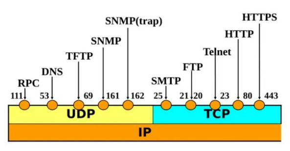
The fourth layer of the OSI model is the transport layer. The transport layer is responsible for end-to-end communication, that is, coordinating communication between network source and target systems. In the IP protocol stack, this is the protocol layer where TCP (a transport protocol) and UDP (User Packet Protocol) reside. In layer 4, TCP and UDP headers contain port numbers that uniquely distinguish which application protocols (such as HTTP, FTP, etc.) each packet contains. Endpoint systems use this information to distinguish data in packets, and in particular the port number enables a receiving computer system to determine the type of IP packet it has received and deliver it to the appropriate high-level software. The combination of a port number and a device IP address is often called a socket. The port numbers between 1 and 255 are reserved. They are called “familiar” ports, that is, they are the same across all host implementations of the TCP/IP stack. Standard UNIX services are assigned port numbers ranging from 256 to 1024, with the exception of the “familiar” port number. Custom applications are assigned port numbers above 1024. The most recent list of Assigned port Numbers can be found on RFc1700 “Assigned Numbers”. The TCP/UDP port number provides additional information that can be utilized by the network switch, which is the basis of Layer 4 switching.
Examples of familiar port numbers are:
Application protocol port number
FTP 20 (Data), 21 (Control)
TELNET 23
SMTP 25
HTTP 80
NNTP 119
NNMP 16 162 (SNMP traps)
The TCP/UDP port number provides additional information that can be utilized by the network switch, which is the basis of Layer 4 switching. A Layer 4 switch can act as a “virtual IP” (VIP) front end to a server. Configure a VIP address for each server and server groups that support single or generic applications. The VIP address is sent out and registered on the domain name System. When making a service request, the Layer 4 switch recognizes the start of a session by determining the TCP start. It then uses complex algorithms to determine the best server to handle the request. Once this decision is made, the switch will be associated with a specific IP address, replacing the VIP address on the server with the real IP address of the server. Each Layer 4 switch holds a connection table associated with the source IP address and source TCP port that match the selected server. The Layer 4 switch then forwards the connection request to this server. All subsequent packets are remapped and forwarded between client and server until the switch discovers the session. In the case of Layer 4 switching, access can be linked to real servers to meet user-specified rules, such as having an equal amount of access on each server or allocating traffic according to the capacity of different servers.