The six key points of switches selection are:
- Standard(fixed switch/modular switch)
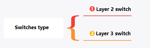
- Functions (Layer 2 Switch/Layer 3 Switch)
- Number of ports
- Port bandwidth
- Switching capacity
- Packet forwarding rate
Switch Standard
The current switch is mainly divided into fixed switches and modular switches.
Fixed switch
- With fixed switches, ports, interfaces, power supplies, and cooling fans are set and cannot be changed, added, or altered. Therefore, fixed switches do not have scalability.
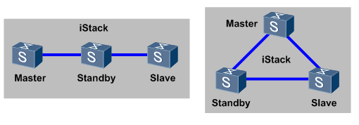
- In order to improve scalability, fixed switches can support stacking technology, which allows multiple box switches to logically form a single switch.

- Normally, fixed switches are applied in the access or aggregation layer of a network.
Modular switch
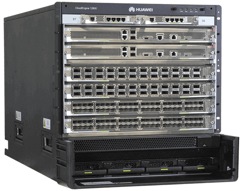
modular switches can be independently configured based on subracks, interface board cards, switchboard cards, and power modules. modular switches generally scale based on the number of slots.
modular switches are typically used at the core of a network.
Functions
Classified according to the working protocol layer
Switches can be divided into Layer 2 switches and Layer 3 switches.
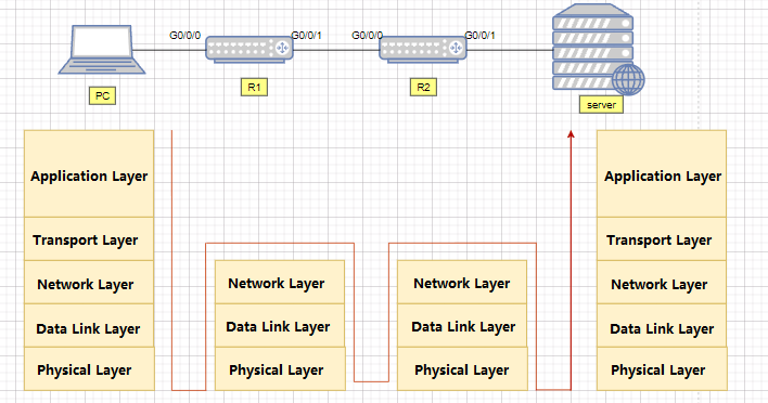
The difference between layer 2 and layer 3 switch
Layer 2 switch:
Switches work on the second data link layer of the OSI reference model, and their main functions include physical addressing, error checking, frame sequencing, and flow control. (As shown in the figure below, Layer 2 switches work at the data link layer and can handle data frames)
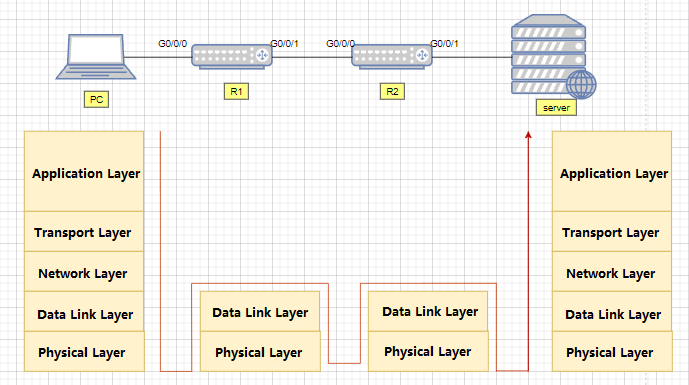
Layer 3 switch:
A device with Layer 3 switching function, i.e. a Layer 2 switch with Layer 3 routing function. But it is an organic combination of the two, not simply superimposing the hardware and software of a router device on a LAN switch. (The following figure shows a Layer 3 switch working at the network layer, which can handle packets)
Number of Ports
Fixed switch
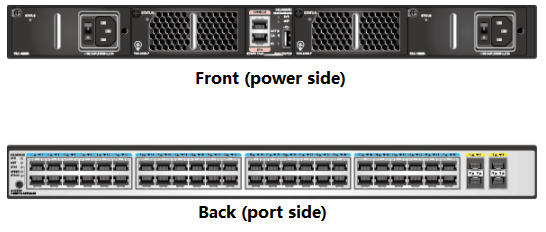
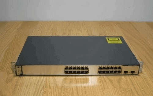
The number of ports that a switch can provide is basically fixed for each type of box switch. Generally, 24 or 48 ports and 2-4 uplink ports are provided.
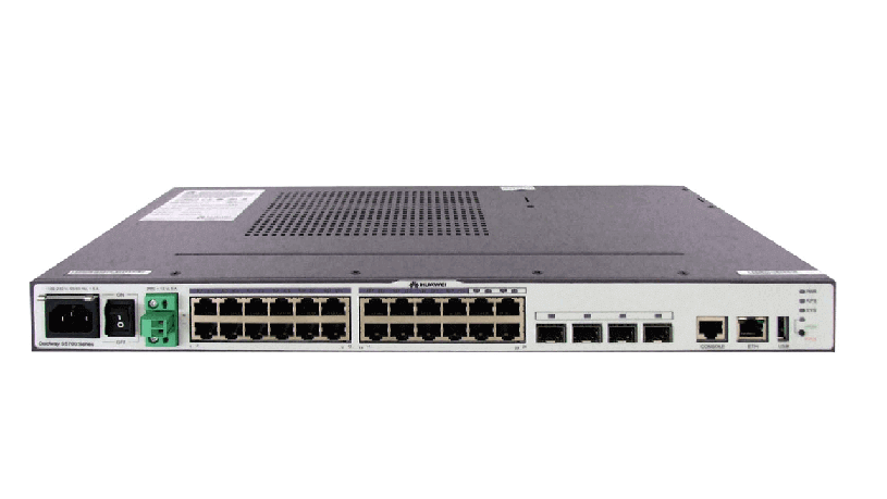
HW CE5850-48T4S2Q-EI is used as an example (as shown below). There are 48 1000M ports, four 10 Gbit/s uplink ports, and two 40 Gbit/s uplink ports.
Modular Switches
The modular switch is related to the number of configured single boards, which generally refers to the maximum number of ports that each frame can support when configuring the highest-density interface board.
HW’s CE12804, for example, supports four service boards LPU, and the ports are related to the specific single-board model. We take the 36-port 100G single board as an example, then insert a full single board that has a total of 144 100G ports.
When choosing a switch you need to base it on the current business situation and future scalability. The number of switch ports represents the number of terminals you need to access.
Take a switch with 48 access points as an example. If 1 terminal occupies one port, then one switch can connect 48 terminals. If it is a company of 200 people, then 5 such switches are needed.
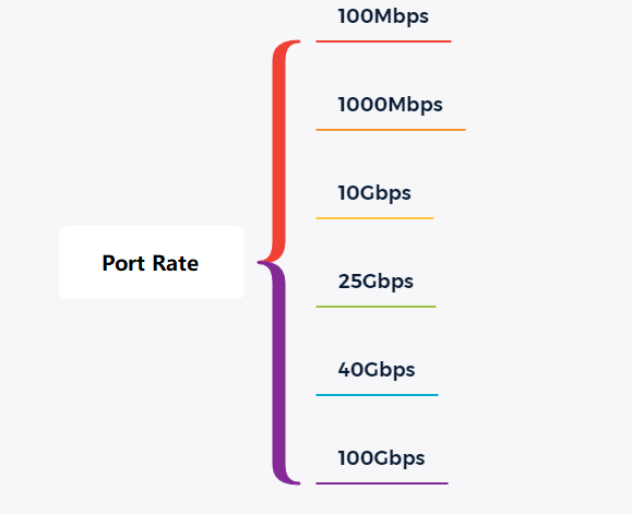
Port Rate
The switch supports port rates:
The current port rates provided by the switch are 100Mbps/1000Mbps/10Gbps/25Gbps, etc.
Switch port rate units:
The unit of port rate of the switch is bps (bit per second), that is, how many bits per second.

Switching Capacity
- Switching capacity: Also known as backplane bandwidth or switching bandwidth.
Switching capacity is the maximum amount of data that can be throughput between the switch interface processor (or interface card) and the data bus.
The backplane bandwidth marks the total data exchange capacity of a switch and is measured in Gbit/s.
The higher the switching capacity of a switch, the more data it can handle, but also the higher the design cost. Twice the sum of all port capacity ports should be less than the switch capacity to achieve full duplex non-blocking switching.
- The switching capacity is related to the switch standard:
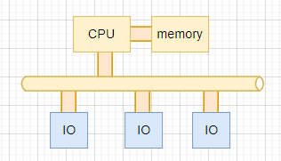
(1) For bus switches, the switching capacity refers to the bandwidth of the backplane bus;
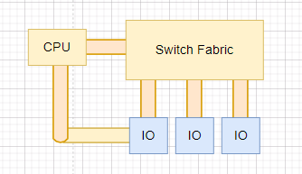
(2) For switch matrix switches, the switching capacity refers to the total bandwidth of the switch matrix interfaces.
This switching capacity is a theoretical calculation, but it represents the maximum switching capacity that the switch may achieve. The current switch design ensures that this parameter does not become a bottleneck for the entire switch.
Packet Forwarding Rate
- Switch Packet Forwarding Rate
Packet forwarding rate, also known as interface throughput, refers to the packet forwarding capacity on an interface of a communication device, usually in pps (packet per second). The packet forwarding rate of the switch is generally the result of actual measurements, representing the actual forwarding performance of the switch.
- Packet Forwarding Rate Calculation
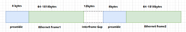
The packet forwarding rate is measured by the number of 64-byte packets (minimum packet) sent per unit of time as the basis for calculation. When calculating the packet forwarding rate, the fixed overhead of the preamble and Interframe Gap should be considered.
By default, the Interframe gap is 12 bytes maximum and users are recommended to use the default configuration. If the user modifies the Interframe gap of the interface to a smaller value, the receiver may not have enough time to receive the next frame after receiving a data frame, resulting in packet loss due to the inability to process forwarded messages in time.
The length of an Ethernet frame is variable, but the processing power used by the switch to process each Ethernet frame is independent of the length of the Ethernet frame. Therefore, the shorter the length of an Ethernet frame, the more frames the switch needs to process and the more processing power it needs to consume, given a certain interface bandwidth of the switch.
Cameras and Surveillance Switch Selection
In HD network video monitoring systems, there are often customer feedback screen delays, lagging, and other phenomena, causing this phenomenon for a number of reasons, but in most cases or the switch, configuration is not reasonable enough, resulting in insufficient bandwidth caused by.
In terms of network topology, a large HD network video surveillance system needs to use a three-layer network architecture: access layer, convergence layer, and core layer.
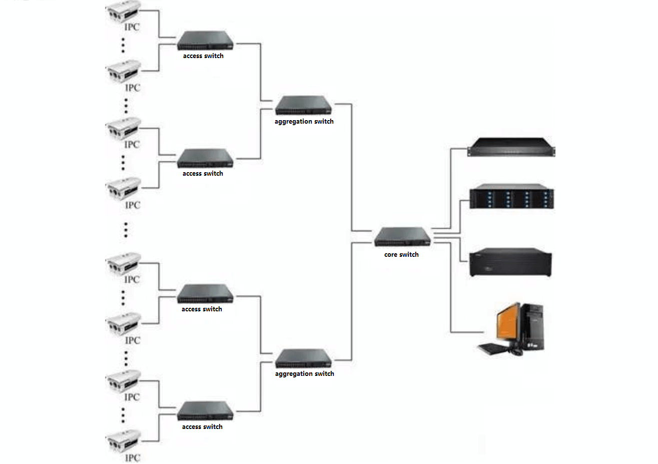
- Access layer switch selection
Access layer switches are mainly down-linked front-end network HD cameras and up-link aggregation switches. To 720P network camera 4M data rate calculation, a 100 megabit access switch can access the maximum number of 720P network cameras.
The actual bandwidth of our commonly used switches is 50%-70% of the theoretical value, so the actual bandwidth of a 100 megabit port in 50M-70M. 4M * 12 = 48M, so it is recommended that a 100-megabit access switch access a maximum of 12 720P network cameras.
It should be considered that the current network monitoring adopts dynamic coding mode, and the peak value of the camera bitstream may exceed 4M bandwidth. At the same time, bandwidth redundancy is considered. So a 100 megabit access switch control within 8 units when the best, more than 8 units recommended the use of gigabit ports.
- Selection of aggregation layer switch
Switches at the aggregation layer connect to switches at the access layer and core switches in the monitoring center. Generally, the aggregation switch must be a Layer 2 switch with a gigabit upload port.
Based on the 4M data rate of 720P network cameras, each front-end access layer switch has six 720P network cameras, and the aggregation switch connects to five access layer switches. The total bandwidth of the aggregation layer switch is 4M*6*5=120M. Therefore, the aggregation switch and core switch must be cascaded through gigabit ports.
- Selection of core layer switches
The switch at the core layer connects to the switch at the aggregation layer and connects to the video monitoring platform, storage server, digital matrix, and other devices in the monitoring center. It is the core of the entire HD network monitoring system. When selecting the core switch, the bandwidth capacity of the whole system and improper configuration of the core switch must be considered, which will inevitably lead to the smooth display of the video picture. Therefore, the monitoring center must select the all-gigabit core switch. If the number of points is large, VLANs need to be divided and Layer 3 full gigabit port core switches need to be selected.
Backplane bandwidth:
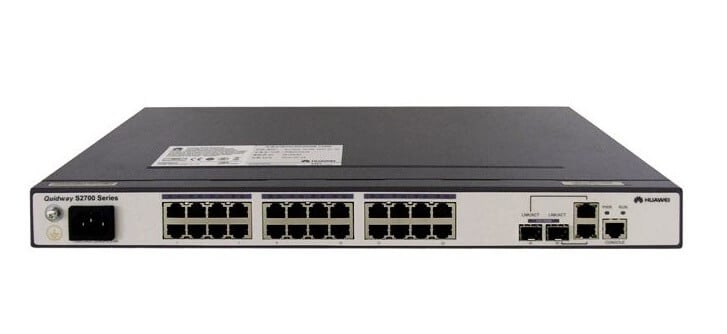
Calculation method: Number of ports * port speed * 2 = backplane bandwidth. Take HW S2700-26TP-SI as an example, the switch has 24 100-gigabit ports and two-gigabit uplink ports.
Backplane bandwidth=24*100*2/1000+2*1000*2/1000=8.8Gbps.
Packet forwarding rate:
Calculation method: Number of fully configured GE ports * 1.488Mpps + Number of fully configured 100 Gigabit ports * 0.1488Mpps = packet forwarding rate (the theoretical throughput of 1 Gigabit port at packet length of 64 bytes is 1.488Mpps, and the theoretical throughput of 1 100 Gigabit port at packet length of 64 bytes is 0.1488Mpps). Take HW S2700-26TP-SI as an example, the switch has 24 100-gigabit ports and two-gigabit uplink ports.
Packet forwarding rate = 24*0.1488Mpps + 2*1.488Mpps = 6.5472Mpps.
Common switch configuration commands
HW Switch Basic Configuration Commands
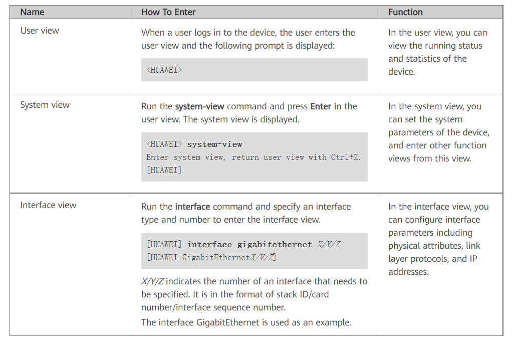
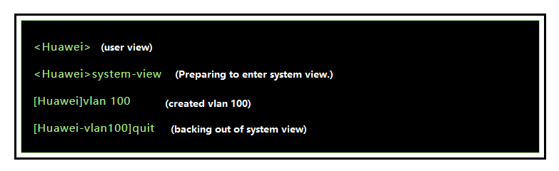
Common commands view
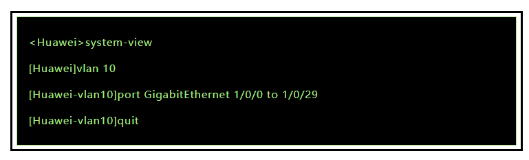
Creating VLANs
Adding ports to VLANs
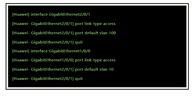
Adding multiple ports to VLANs
Configuring an IP address for the switch
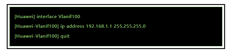
Configuring the default Gateway

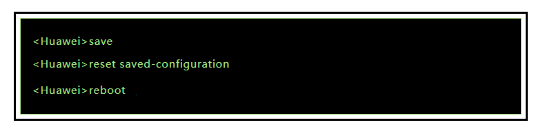
Save Settings and Reset Commands
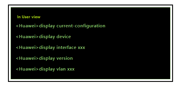
Common display commands
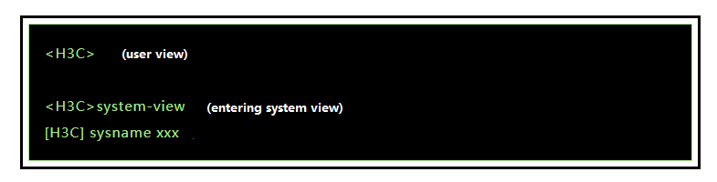
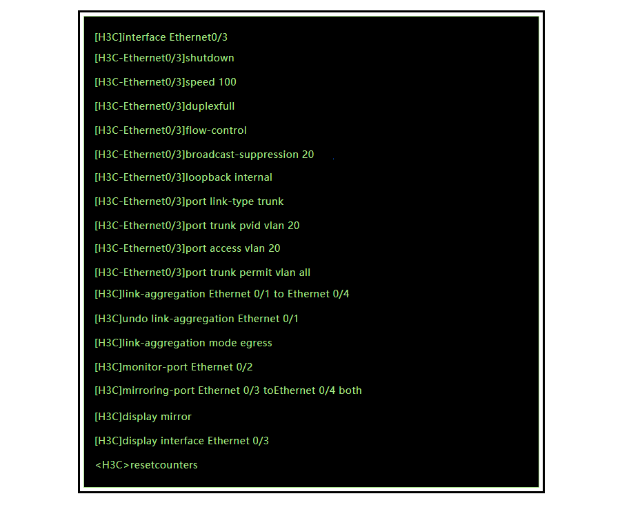
Basic Configuration of H3C Switches
Basic Configuration
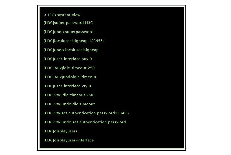
User Configuration
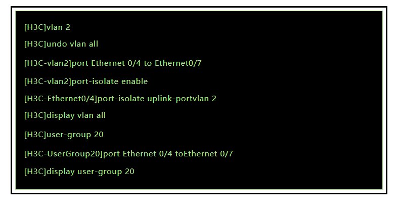
VLAN configuration
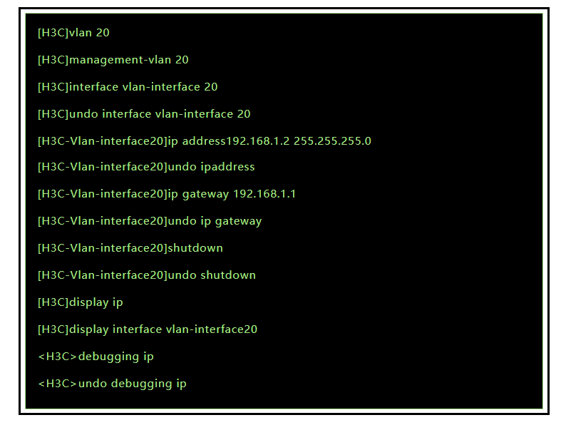
Switch IP Configuration
DHCP Client Configuration
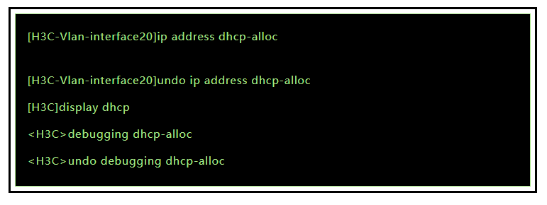
Port Configuration
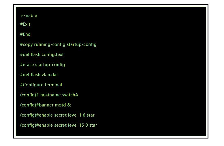
Ruijie switch basic command configuration
Basic Commands
View information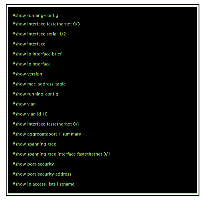
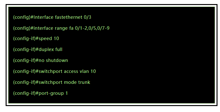
Basic port configuration
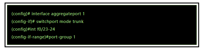
Port aggregation configuration
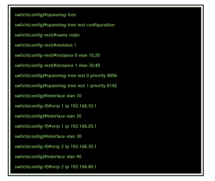
Spanning tree
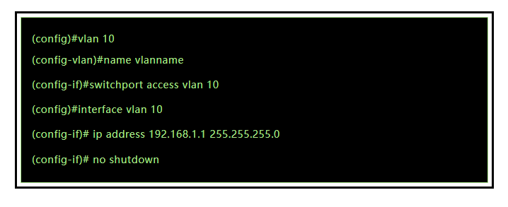
Basic VLAN configuration
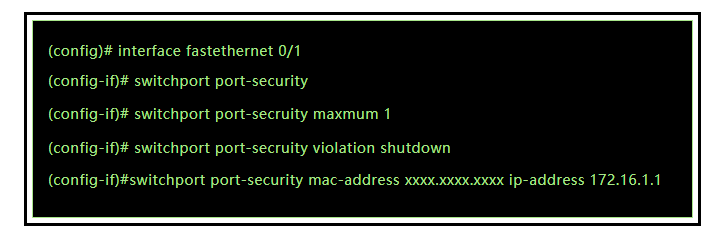
Port security
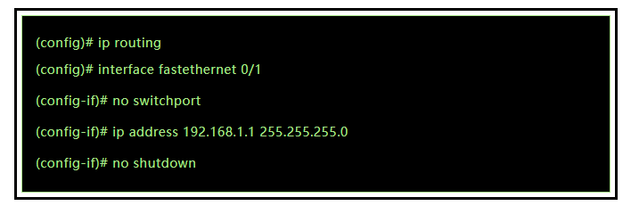
Layer 3 Routing Function (for Layer 3 switches)
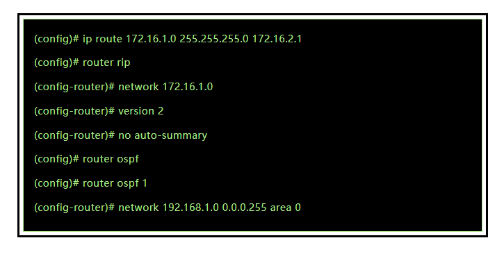
Layer 3 switch routing protocol
Related Products:
-
 SFP-10G85-SR 10G SFP+ SR 850nm 300m LC MMF DDM Transceiver Module
$12.00
SFP-10G85-SR 10G SFP+ SR 850nm 300m LC MMF DDM Transceiver Module
$12.00
-
SFP-10G85-SRI 10G SFP+ SR 850nm 300m LC MMF DDM Industrial High Temperature Transceiver Module
$13.00
-
SFP-10G31-IR 10G SFP+ IR 1310nm 2km LC SMF DDM Transceiver Module
$15.00
-
Alcatel-Lucent SFP-10G-LRM Compatible 10G SFP+ LRM 1310nm 220m LC MMF DDM Transceiver Module
$15.00
-
SFP28-25G-ESR 25G SFP28 ESR 850nm OM3 200m/OM4 300m LC MMF DDM Transceiver Module
$35.00
-
SFP28-25G-LR 25G SFP28 LR 1310nm 10km LC SMF DDM Transceiver Module
$45.00
-
SFP28-25G-ERI 25G SFP28 ER 1310nm 40km LC SMF DDM I-temp Transceiver Module
$360.00
-
SFP28-25G-ZR 25G SFP28 ZR 1300nm 80km LC SMF DDM Transceiver Module
$1100.00
-
QSFPP-40G-ZR4 40G QSFP+ ZR4 LWDM4 80km LC SMF DDM Optical Transceiver Module
$1200.00
-
QSFPP-40G-BD-RX 40G QSFP+ Bi-Directional 850nm/900nm 100m/150m Duplex LC MMF Optic Module Receiver Only
$165.00
-
Gigamon QSF-503 Compatible 40G QSFP+ LR4 1310nm (CWDM4) 10km LC SMF DDM Transceiver Module
$149.00
-
QSFPP-40G-ER4 40G QSFP+ ER4 1310nm (CWDM4) 40km LC SMF DDM Transceiver Module
$449.00
-
QSFP28-100G-SR4 100G QSFP28 SR4 850nm 100m MTP/MPO MMF DDM Transceiver Module
$40.00
-
QSFP28-100G-LR4 100G QSFP28 LR4 1310nm (LAN WDM) 10km LC SMF DDM Transceiver Module
$285.00
-
Q28-100G32-BX20 100G QSFP28 BIDI TX1311nm/RX1291nm Single Lambda LC SMF 20km PAM4 DDM Optical Transceiver Module
$600.00
-
QSFP28-100G-SRBD Dual Rate 40G/100G QSFP28 BIDI 850nm & 900nm 100m LC MMF DDM Optical Transceiver
$449.00