
What is VLAN?
VLAN is Virtual Local Area Network, not “VPN” (Virtual Private Network). VLAN is an emerging data exchange technology that divides LAN devices logically (not physically) into segments to realize virtual workgroups. This emerging technology is mainly used in switches and routers, but the mainstream application is still in the switches. However, not all switches have this function, only switches with VLAN protocol above layer 3 have this function, which can be known by checking the manual of the corresponding switch.
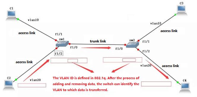
The IEEE issued the draft 802.1Q protocol standard in 1999 to standardize the VLAN implementation scheme. The emergence of VLAN technology allows administrators to logically divide different users within the same physical LAN into different broadcast domains according to the actual application requirements. Each VLAN contains a group of computer workstations with the same requirements and has the same attributes as the physically formed LAN. Since it is divided logically, not physically. So individual workstations within the same VLAN are not restricted to the same physical range, i.e., these workstations can be in different physical LAN segments. From the characteristics of VLANs, it is clear that both broadcast and unicast traffic within a VLAN is not forwarded to other VLANs, thus helping to control traffic, reduce equipment investment, simplify network management, and improve network security.
The development of switching technology has also accelerated the adoption of new switching technologies (VLANs). By dividing the enterprise network into virtual network VLAN segments, network management and network security can be enhanced and unnecessary data broadcasting can be controlled.
In a shared network, a physical network segment is a broadcast domain. In a switched network, a broadcast domain can be a virtual segment with an arbitrary set of selected Layer 2 network addresses (MAC addresses). In this way, the division of workgroups in a network can break through the geographic constraints in a shared network and instead be based entirely on management functions. This workflow-based grouping model greatly improves the management function of network planning and reorganization.
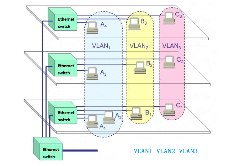
Workstations in the same VLAN, regardless of which switch they are actually connected to, communicate with each other as if they were on separate switches. Broadcasts in the same VLAN can only be heard by members of the VLAN, and are not transmitted to other VLANs, which can well control the generation of unnecessary broadcast storms. At the same time, without routing, different VLANs cannot communicate with each other, which increases the security between different departments in the enterprise network.
Network administrators can configure the routes between VLANs to fully manage the information access between different management units within the enterprise. The switch is divided into VLANs based on the MAC address of the user’s workstation. Therefore, a user is free to move his office to the enterprise network, and no matter where he accesses the switching network, he can communicate with other users in the VLAN freely.
VLAN networks can be composed of devices with mixed network types, such as 10M Ethernet, 100M Ethernet, token network, FDDI, CDDI, etc., and can be workstations, servers, hubs, network uplink backbones, etc.
In addition to the advantages of dividing the network into multiple broadcast domains, thus effectively controlling the occurrence of broadcast storms and making the topology of the network very flexible, VLANs can also be used to control access between different departments and sites in the network.
VLAN is a protocol proposed to solve the broadcasting problem and security of Ethernet. It adds VLAN header to Ethernet frames, divides users into smaller workgroups with VLAN IDs, and restricts users to visit each other between different workgroups, and each workgroup is a virtual LAN. The advantage of virtual LAN is that it can limit the broadcast range and can form virtual workgroups to manage the network dynamically.
VLAN division methods
The implementation methods of VLAN on the switch can be divided into six categories:
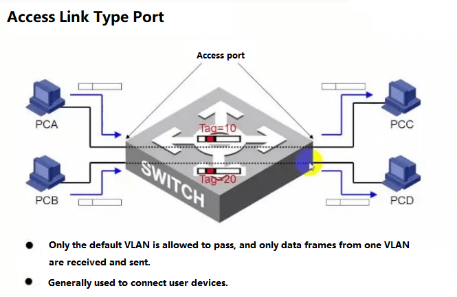
1. Divide VLAN based on ports
This is the most commonly used VLAN division method, and it is the most widely used and effective, and most of the VLAN protocol switches provide this VLAN configuration method.
This method of VLAN division is based on the switching ports of Ethernet switches. It divides the physical ports on the VLAN switch and the PVC (Permanent Virtual Circuit) ports inside the VLAN switch into several groups, and each group constitutes a virtual network, which is equivalent to an independent VLAN switch.
For when different departments need to access each other, they can be forwarded through a router with MAC address-based port filtering. The set of passable MAC addresses is set on the corresponding port of the switch, routing switch, or router closest to the site on the access path of a site. This prevents the possibility of illegal intruders stealing IP addresses from within to break in from other access points.
As we can see from this division method itself, the advantage of this method is that it is very simple to define VLAN membership, as long as all ports are defined as the corresponding VLAN groups. It is suitable for networks of any size. Its disadvantage is that if a user leaves the original port and goes to a port on a new switch, it must be redefined.
2. Divide VLANs based on MAC address
This method of dividing VLANs is based on the MAC address of each host, i.e., each host with a MAC address is configured with the group to which it belongs. The mechanism it implements is that each NIC corresponds to a unique MAC address and the VLAN switch keeps track of the addresses belonging to the VLAN MAC. This approach to VLANs allows network users to automatically retain membership in the VLAN to which they belong when they move from one physical location to another.
As can be seen from the mechanism of this division, the biggest advantage of this method of VLAN division is that VLANs do not have to be reconfigured when users move their physical location, i.e., when they switch from one switch to another. This is because it is based on the user, not on the port of the switch. The disadvantage of this method is that all users must be configured during initialization. The configuration process can take a long time if there are hundreds or even thousands of users, so this partitioning method is usually suitable for small LANs.
In addition, this partitioning method also reduces the efficiency of switch execution, because there may be many members of VLAN groups on each switch port, storing the MAC addresses of many users, which is not easy to query.
In addition, for laptop users, their network cards may be changed frequently, so the VLAN must be configured frequently.
3. DivideVLANs based on network layer protocols
VLANs are divided by network layer protocol and can be classified into VLAN networks such as IP, IPX, DECnet, AppleTalk, Banyan, etc. Such VLANs, composed of network layer protocol, enable broadcast domains to span multiple VLAN switches. This is very attractive to network administrators who want to organize users for specific applications and services. Moreover, users can move freely within the network, but their VLAN membership remains intact.
The advantages of this method are that the physical location of the user changes without reconfiguring the VLAN to which it belongs and that VLANs can be classified according to protocol type, which is important for network administrators. Also, this method does not require additional frame tags to identify VLANs, which can reduce the amount of traffic on the network. The disadvantage of this approach is that it is inefficient because checking the network layer address of each packet is time-consuming to process (compared to the previous two approaches). Generally, switch chips can automatically check the Ethernet frame headers of packets on the network, but it takes a higher level of skill and is also more time-consuming to enable the chip to check IP frame headers. Of course, this is related to each vendor’s implementation method.
4. Divide VLANs based on IP multicast
IP multicast is actually a definition of VLAN, that is, an IP multicast group is a VLAN. This division method extends the VLAN to the WAN, so this method has greater flexibility, and it is easy to extend through the router. It is mainly suitable for the LAN users who are not in the same geographical range to form a VLAN. It is not suitable for LANs because it is not efficient.
5. Divide VLANs by policy
Policy-based VLANs can be assigned in various ways, including VLAN switch ports, MAC addresses, IP addresses, and network layer protocols. Network administrators can determine the VLAN type based on their own management mode and unit requirements.
6. DivideVLANs by user-defined, non-user authorization
VLAN allocation based on user definition and non-user authorization means that VLANs are defined and designed according to the special requirements of network users to meet special VLAN networks. In addition, non-VLAN users can access VLANs only after being authenticated by the VLAN management by providing user passwords.
The advantages of VLAN
For any new technology to be widely supported and applied, there must be some key advantages, and so does VLAN technology, whose advantages are mainly reflected in the following aspects:
- Increased the flexibility of network connection
The VLAN technology combines different locations, networks, and users to form a virtual network environment, which is as convenient, flexible, and efficient as using a local LAN. VLAN can reduce the overhead of moving or changing the location of workstations, especially for companies with frequently changing business conditions.
- Control the broadcast on the network
The VLAN provides a firewall mechanism to prevent excessive broadcasting on the switching network. Using VLANs, a switch port or user can be assigned to a specific VLAN group, which can be within a switch network or across multiple switches, and broadcasts within a VLAN will not be sent outside the VLAN. Similarly, adjacent ports do not receive broadcasts generated by other VLANs. This reduces broadcast traffic, releases bandwidth for user applications, and reduces broadcast generation.
- Improve network security
Because a VLAN is a separate broadcast domain. VLANs are isolated from each other, which improves network utilization and ensures network security and confidentiality. People often transmit confidential and critical data on the LAN. Confidential data should be provided with security means such as access control. An effective and easy-to-implement method is to segment the network into several different broadcast groups, where the network administrator limits the number of users in the VLAN and prohibits access to applications in the VLAN without permission. Switching ports can be grouped based on application type and access privileges, and restricted applications and resources are typically placed in security VLANs.
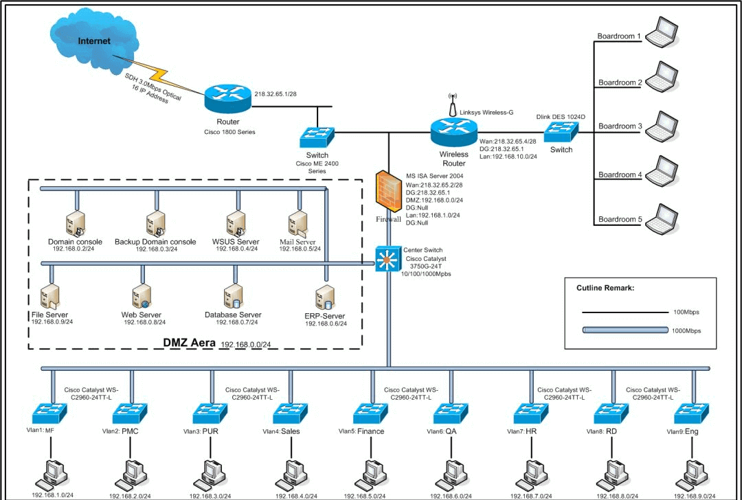
Case study of VLAN configuration
A company has about 100 computers, and there are four major departments that mainly use the network: Production Department (20), Finance Department (15), human resources Department (8), and Information Center (12).
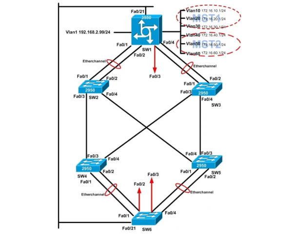
The entire network uses three Catalyst 1900 managed switches (named: Switch1, Switch2, and Switch3 respectively, each switch is connected to several hubs as needed, mainly for non-VLAN users, such as administrative paperwork, temporary users, etc.) and one Cisco 2514 router in the middle and back part of the network, and the entire network is connected to the Internet through router Cisco 2514 is connected to the external Internet.
The connected users are mainly distributed in four parts, namely: production department, finance department, information center, and human resources department. These four parts are mainly divided into separate VLANs to ensure that the corresponding departmental network resources are not stolen or damaged.
In order to ensure the security of network resources, especially for sensitive departments such as finance and human resources, the information on the network is not allowed to be accessed by too many people. Therefore, the company adopts the VLAN method to solve the above problems.
Vlans can be divided into the production department, Finance Department, human resources Department, and information center. The corresponding VLAN groups are Prod, Fina, Huma, and Info. Table 1 shows the network segments of each VLAN group.
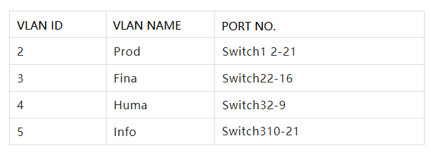
Note: The reason why the VLAN ID of the switch starts from “2” is because the switch has a default VLAN, that is VLAN “1”, which includes all the users connected to the switch.
VLAN configuration process
The VLAN configuration process is actually very simple, requiring only two steps.
(1) Naming each VLAN group.
(2) Corresponding the corresponding VLAN to the corresponding switch port.
The following is the specific configuration process.
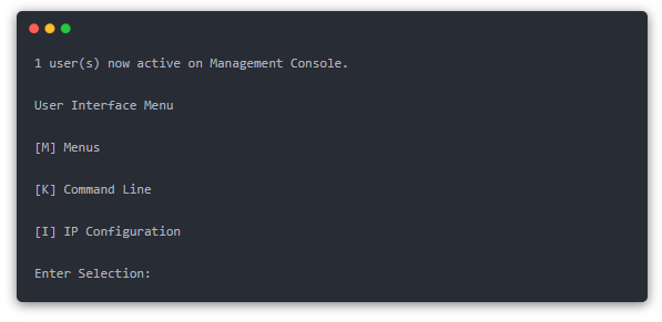
Step 1: Set up the HyperTerminal, connect to the 1900 switch, and configure the switch’s VLANs through the HyperTerminal. The main configuration interface appears after a successful connection as shown below (basic information has been configured on the switch before):
Note: HyperTerminal is implemented using the Hypertrm program that comes with Windows. For details, see related documents.
Step 2: Click “K” and select “[K] Command Line” from the main menu to enter the following command line configuration interface:
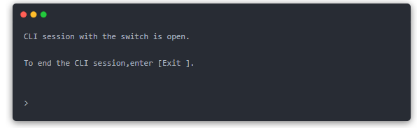
At this point we enter the normal user mode of the switch, just like the router, this mode can only view the current configuration, can not change the configuration, and can use a very limited command. So we must enter the “privileged mode”.
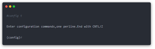
Step 3: Enter the command “enable” at the “>” prompt in the previous step to enter the privileged mode. The command format is “>enable”, and then the switch is displayed:
Step 4: For security and convenience, we give each of the 3 Catalyst 1900 switches a name and set a privileged mode login password. The following is an example of Switch1. The configuration code is as follows:
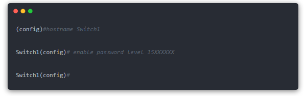
Note: The privileged mode password must contain 4 to 8 characters. The entered password is displayed in plaintext, so keep it confidential. The switch uses the level to determine password permissions. Level 1 is the password for accessing the command line interface. After you set the password for level 1, the next time you connect to the switch and type K, you will be asked to enter the password, which is the password set for level 1. level 15 is the privileged mode password that you will be asked to enter after typing the “enable” command.
Step 5: Set the VLAN name. Because the four VLANs belong to different switches, the VLAN naming command is “VLAN, VLAN number, name, VLAN name. In Switch1, Switch2, and Switch3, configure the code of VLAN 2, 3, 4, and 5 as follows:
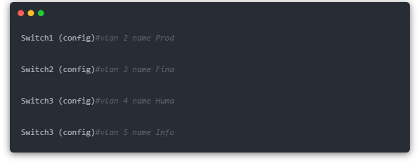
Note: The above configuration is performed according to the rules in Table 1.
Step 6: In the previous step, we configured the VLAN groups for each switch. Now we need to match these VLANs to the switch port numbers specified in Table 1. The command corresponding to the port number is vlan-membership static/ dynamic VLAN number. In this command, either “static” or “dynamic” must be selected, but usually choose “static”.
The VLAN port number application is configured as follows.
(1) The VLAN port number of the switch named “Switch1” is configured as follows.
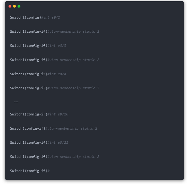
Note: “int” is the abbreviation of “interface” command. e0/3″ is the abbreviation of “ethernet 0/2”, which represents port 2 of module 0 of the switch.
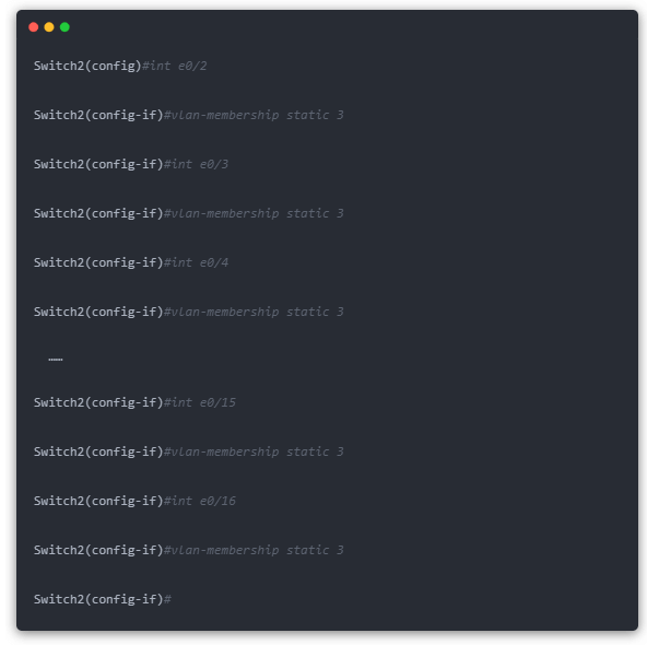
(2) The VLAN port number of the switch named “Switch2” is configured as follows.
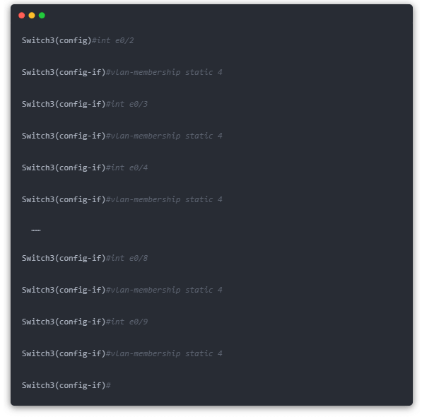
(3) The VLAN port number of the switch named “Switch3” is configured as follows (it includes the configuration of two VLAN groups), see the configuration code of VLAN 4 (Huma) first.
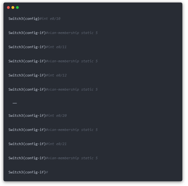
The following is the configuration code for VLAN 5 (Info).
Now we have defined the VLANs on the corresponding ports of the switch as required in Table 1. In order to verify our configuration, you can use the “show vlan” command in privileged mode to display the configuration just made to check whether it is correct.
The above is an introduction to the VLAN configuration of the Cisco Catalyst 1900 switch, the VLAN configuration of other switches is basically similar, refer to the relevant switch manual.