ToR
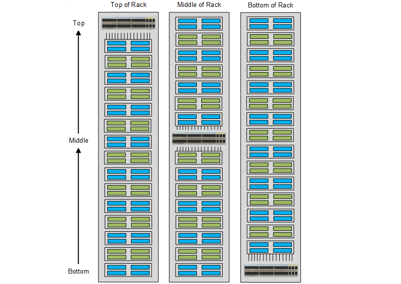
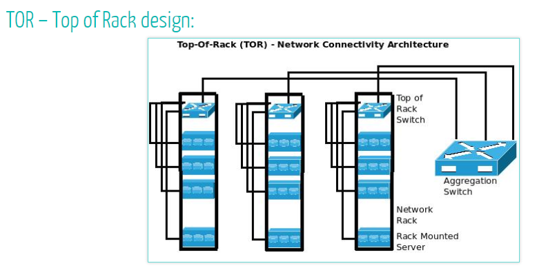
TOR (Top of Rack) refers to the deployment of one or two switches in each server rack, with the servers directly connected to the switches in the rack, enabling the interconnection of servers and switches within the rack. The actual core of TOR is to deploy the switches inside the server rack, either at the top of the rack or at the middle the rack or bottom of the rack, as shown in the figure. This is shown in the figure. Generally speaking, deploying the switches at the top of the rack is most beneficial, so this architecture is the most used.
Switches deployed in TOR mode on server cabinets, we call them TOR switches. TOR switches are usually undertaken by box switches with a height of 1U to 2U, such as HW’s CE5800 and CE6800 series switches.
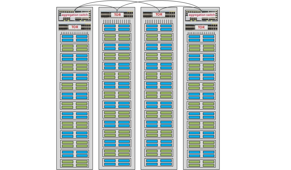
The greatest advantage of the TOR architecture is that it simplifies the connection between servers and switches. The GE/10GE/25GE ports on the servers in the cabinet can be directly connected to the TOR switch through short jumpers, and then connected to the aggregation switch through 10GE, 40GE, or 100GE optical fibers, as shown in the figure below. This connection greatly shortens the distance between cables, simplifies cable management, reduces the complexity of the network structure, and conforms to the trend of green and energy-saving data centers. It is also convenient to replace cables when service expansion is required.
For the TOR architecture, each cabinet can be seen as a separate administrative entity. When servers or switches need to be upgraded, you can upgrade them cabinet one by the cabinet. During the upgrade, traffic forwarding of other cabinets is not affected and the impact on services is minimized.
Fiber is usually chosen for TOR switch uplink because of its advantages over copper for long-term investment protection. Optical fibers can carry higher bandwidths. When a link with a higher rate needs to be replaced, optical fibers are more flexible.
Therefore, when selecting TOR switches, you usually need to consider both the number and rate of downstream ports connected to servers and the flexibility of upstream ports. In general:
◼ When the server port is GE port, you can choose CE5855EI series switch. CE5855EI series switch is divided into two models, CE5855-48T4S2Q-EI and CE5855-24T4S2Q-EI, which provide 48 and 24 10/100/1000BASE-T Ethernet electrical interfaces on the downlink, respectively. interfaces; the uplink provides two 40GE QSFP+ Ethernet optical interfaces and four 10GE SFP+ Ethernet optical interfaces, while each 40GE interface also supports splitting into four 10GE interfaces.
◼ When the server port is a 10GE port, you can choose CE6856HI series switches. CE6856HI series switches are divided into two models, CE6856-48S6Q-HI and CE6856-48T6Q-HI, which provide 48 10GE SFP+ Ethernet optical interfaces on the downlink and 10GBASE-T The CE6856-48S6Q-HI and CE6856-48T6Q-HI series switches provide 48 10GE SFP+ Ethernet optical interfaces and 10GBASE-T Ethernet electrical interfaces on the downlink, and 6 40GE QSFP+ Ethernet optical interfaces on the uplink.
◼ If you want the TOR switch to provide a large cache, it is recommended that you choose the CE6870EI series switch. According to the type and number of downlink ports, the CE6870 series switches are divided into three models: CE6870-48S6CQ-EI, CE6870-24S6CQ-EI, and CE6870-48T6CQ-EI. Taking the CE6870-48S6CQ-EI shown in Figure 3 as an example, the switch supports six 40GE/100GE QSFP28 Ethernet optical interfaces on the uplink and also supports splitting into four 10GE or four 25GE interfaces. The CE6870 series switches offer a large cache of 4GB, which can easily cope with traffic surges caused by video, search, and other applications in the data center.
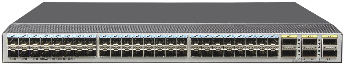
HW CE6870-48S6CQ-EI
Of course, the TOR architecture also has its drawbacks. One of the most obvious is that the TOR architecture expands the management domain of the entire data center server room. Deploying switches on each cabinet means that there are more switches in the room, each of which needs to be configured, managed, and maintained. Assuming you have 10 rows of cabinets in your server room, 10 cabinets in each row, and two TOR switches deployed on each cabinet, you would need to manage and maintain 200 TOR switches. Although the configuration of these 200 switches is basically the same, it still requires a lot of labor costs and increases the probability of misallocation of the equipment.
The CE Series switches also provide solutions for the above problems. For example, you can use the ZTP (Zero Touch Provisioning) function for batch auto-configuration of newly shipped or empty configuration devices. The CE series switches also support rich device virtualization technologies (such as stacking), which can effectively simplify the management plane of devices, thus reducing labor costs and improving Deployment efficiency.
Another drawback of TOR architecture is port waste. Currently, most TOR switches can provide 48 GE/10GE/25GE downlink ports. If you deploy two TOR switches per cabinet, for example, there are 96 downstream ports, so you would need a large number of servers in the cabinet to make full use of all these ports.
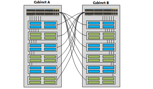
You can reduce port waste to some extent by cross-connecting between adjacent cabinets. As shown in the figure below, a 48-port TOR switch is deployed on each of the two cabinets, with 24 ports on each switch providing access to servers in this cabinet and another 24 ports providing access to servers in adjacent cabinets. As you can see, this solution comes at the cost of additional cabling between the two cabinets, so it’s not a perfect solution either. But it is a cost-effective alternative to the waste of ports caused by deploying two TOR switches per cabinet.
EOR/MOR
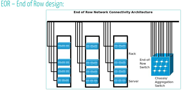
Unlike TOR, EOR (End of Row) architecture provides a unified network access point at the end of each cabinet. As shown in the figure, the switch deployed at the end of each cabinet for servers to access the network in a uniform manner is called an EOR switch.
.png)
To ensure reliability, each row of cabinets is usually equipped with two network cabinets, located at the head and end of the row respectively. The server network adapter uses relatively short RJ45 / DAC / fiber patch cords to connect to the same cabinet’s patch panel, and the network cables, fiber, and copper cables on the patch panel are bundled and connected to the network cabinet at the far end of each row through the overhead cable trunk or floor.
The EOR architecture places the access switches centrally in one or two cabinets, which facilitates management and maintenance, but also increases the connectivity between the server cabinets and the network cabinets. The further the server cabinets are from the network cabinets, the longer the cabling distance in the server room, resulting in a high cable maintenance workload and poor flexibility.
The Middle of Row (MOR) architecture is an improvement of the EOR. It also provides a unified network access cabinet for servers. However, the MOR requires that the network cabinet be placed in the middle of the whole row of cabinets, shortening the distance between the server cabinet and the network cabinet to a certain extent and simplifying cable management and maintenance. However, compared with TOR, both EOR and MOR, complex wiring and difficult management and maintenance are still their biggest disadvantages. Unless otherwise specified, the following EOR descriptions also apply to MOR.
EOR switches are usually chassis switches, such as HW’s CE12800 series switches. If the number of servers in the equipment room is small, you can also choose CE8800 and CE7800 series.
Compared with box switches, chassis switches have obvious advantages in the following aspects:
◼ Provide More and Various Access Ports. By configuring interface boards with different numbers and rates on a chassis switch, you can flexibly control the number and rate of access ports. For example, CE12800 series switches support 36×100GE, 36×40GE, 48×10GE, and 48 GE interface boards (using the maximum number of ports as an example). Ports also support various split types, providing flexible options for accessing different data center servers.
◼ High Reliability. Chassis switches provide redundant hardware, such as multiple switch modules, power modules, and fan modules, to improve system reliability.
◼ Protect Customer Investments. When a data center needs higher access rates than the current one, you only need to replace the interface board with a higher rate rather than the entire unit. From the perspective of the whole life cycle, the cost is lower.
The EOR architecture greatly reduces the administrative domain of the data center because it is managed on a per-row rather than a per-rack basis. However, it also means that if an EOR switch fails or fails to upgrade, it will also affect an entire row of servers. This is why there is a higher demand for EOR switches.
Comparison of TOR and EOR
The simplified diagrams of TOR and EOR are shown in the following two figures.
Disadvantages of EOR cabling: There are many copper cables from server cabinets to network cabinets (about 20-40 copper cables), and the farther the copper cables of server cabinets from network cabinets, the longer the wiring distance in the server room, which leads to large cable management and maintenance workload and poor flexibility.
Disadvantages of TOR cabling: Each server cabinet is limited by the power output, and the number of servers that can be deployed is limited, which leads to insufficient utilization of the access ports of the switches in the cabinet. Sharing one or two access switches among several server cabinets can solve the problem of under-utilization of switch ports, but this approach increases cable management workload.
Considering the network design, the number of VLANs on each access switch in TOR cabling is not large. During network planning, do not allow a VLAN to span multiple access switches through the aggregation switch. Therefore, in a network topology that uses TOR wiring, each VLAN does not have a large range or contain a large number of ports. However, for EOR cabling, the port density of access switches is high. When the network is originally designed, there may be a VLAN with a large number of ports.
TOR mode has a large number of access switches, while EOR mode has a small number of access switches. Therefore, TOR mode requires a large amount of network device management and maintenance.
With the surge in user data service demand, the server density in data center rooms is getting higher and higher, and new technology trends such as virtualization and cloud computing are becoming more and more popular, making the network ports corresponding to servers increase greatly and increasing the complexity of management, in addition, the convergence of Ethernet (LAN) and fiber storage area networks (SAN) is becoming more and more common, which inevitably requires a new network topology with This inevitably requires a new network topology to correspond.
With the tide of cloud computing, this distributed architecture is extremely scalable for business and requires an increasing number of servers.
For example, the new Apache Hadoop 0.23 supports 6,000 to 10,000 servers in a cluster. The massive number of servers requires full utilization of data center cabinet space, while the massive amount of business data also requires faster and more direct high-performance links to deliver the data to the network core. Under such a trend, it is obvious that ToR is more applicable, and under the pressure of rapid business expansion, the ToR approach can better achieve faster network expansion.
Related Products:
-
 SFP28-25G-SR 25G SFP28 SR 850nm 100m LC MMF DDM Transceiver Module
$25.00
SFP28-25G-SR 25G SFP28 SR 850nm 100m LC MMF DDM Transceiver Module
$25.00
-
40G QSFP+ CSR4 850nm 300m MTP/MPO MMF DDM Optical Transceiver Module
$30.00
-
QSFP28-100G-SR4 100G QSFP28 SR4 850nm 100m MTP/MPO MMF DDM Transceiver Module
$40.00
-
Cisco QSFP-100G-CWDM4-S Compatible 100G QSFP28 CWDM4 1310nm 2km LC SMF DDM Transceiver Module
$110.00
-
SFP28-25G-PC3M 3m (10ft) 25G SFP28 to SFP28 Passive Direct Attach Copper Cable
$30.00
-
SFP28-25G-AOC7M 7m (23ft) 25G SFP28 to SFP28 Active Optical Cable
$46.00
-
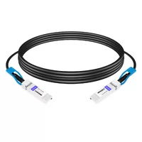
QSFP-40G-PC3M 3m (10ft) 40G QSFP+ to QSFP+ Passive Copper Direct Attach Cable
$23.00
-
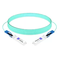
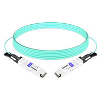
QSFP-40G-AOC-10M 10m (33ft) 40G QSFP+ to QSFP+ Active Optical Cable
$83.00
-
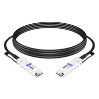
QSFP28-100G-PC3M 3m (10ft) 100G QSFP28 to QSFP28 Copper Direct Attach Cable
$43.00
-
QSFP28-4SFP28-PC3M 3m (10ft) 100G QSFP28 to Four 25G SFP28 Copper Direct Attach Breakout Cable
$80.00