Thanks to the rapid roll-out of 5G communication networks and high-capacity data center construction around the world, the demand for communication bandwidth is soaring. The demand for beyond 100G optical transmission capacity in the aggregation and core layers of 5G optical transport networks and the bandwidth demand in data centers are growing rapidly. These factors are driving the rapid deployment of 200/400G optical modules with higher transmission rates.
On the other hand, low-cost and green low-carbon requirements are driving the development of optical modules to miniaturized packaging, and compact packaging forms such as Quad Small Form Factor Pluggable-Double Density (QSFP-DD) and Octal Small Form Factor Pluggable (OSFP) are gradually replacing the 100G Centum Form-factor Pluggable (CFP) and its improved form CFP2 as the mainstream form factors for 200G and 400G optical modules.
The QSFP-DD is a new package of high-speed pluggable modules whose specifications were released in 2016 and received a lot of attention, and after several modifications, QSFP-DD products became available in 2018. The package’s electrical interface has 8 channels and can be used for 200 or 400G network transmission via Non-Return to Zero (NRZ) modulation or 4 Pulse Amplitude Modulation (PAM4). Its backward compatibility with QSFP+/QSFP28/QSFP56 and other QSFP packages has helped the industry meet the demand for next-generation high-density and high-speed pluggable optical modules, and 200/400G optical modules in QSFP-DD packages are increasingly being used.
With the widespread deployment of high-speed optical modules at rates above 100G, the issue of module heat dissipation has come under greater scrutiny. FiberMall takes 200G QSFP-DD LR4 (Long Range 4) optical module as the research object, models and analyzes the effect of heat sink on the internal temperature change of the module during operation, and studies the heat dissipation effect inside the module under different parameters, which provides a reference for selection of heat sink parameters and optimization of QSFP-DD optical module.
1. Simulation Model of QSFP-DD Optical Module Thermal Analysis
Compared to the QSFP packaged optical modules, the 200G and 400G QSFP-DD packaged optical modules increase the transmission rate and the maximum power consumption exponentially with very little change in internal dimensional space. For example, the power consumption of 100G QSFP28 LR4 optical module is only 3.5 W, while the power consumption of 200G QSFP-DD LR4 optical module is more than 6 W. This will greatly increase the heat and temperature inside the module under the same conditions, and the requirement of 70°C for commercial-grade optical modules makes the internal heat dissipation requirements of the module become more stringent. Therefore, it is necessary to analyze and study the internal heat dissipation of QSFP-DD optical modules.
This article adopts the method of steady-state thermal analysis, based on the heat balance equation of the principle of energy conservation, and considers three types of heat transfer modes: heat conduction, heat convection and heat radiation. Given the boundary conditions of constant temperature and the information of power and thermal conductivity of each component in the optical module, the temperature distribution in the steady state inside the module is calculated by the finite element method. For the QSFP-DD commercial-grade optical module, the simulation sets the temperature boundary condition of 70℃ with reference to the requirement of the protocol that the case temperature should not exceed 70℃.
The main heat generating components inside the 200G QSFP-DD LR4 optical module include Transmitter Optical Subassembly (TOSA), Receiver Optical Subassembly (ROSA), Digital Signal Processing (DSP), Microcontroller Unit (MCU) and power supply chip, etc. In actual modules, these chips are often mounted on both sides of the Printed Circuit Board (PCB) in order to fit enough components in a compact internal space, which also facilitates heat transfer through both sides of the module. Based on the dimensional specifications of the QSFP-DD package, a simulation model was created as shown in Figure 1.
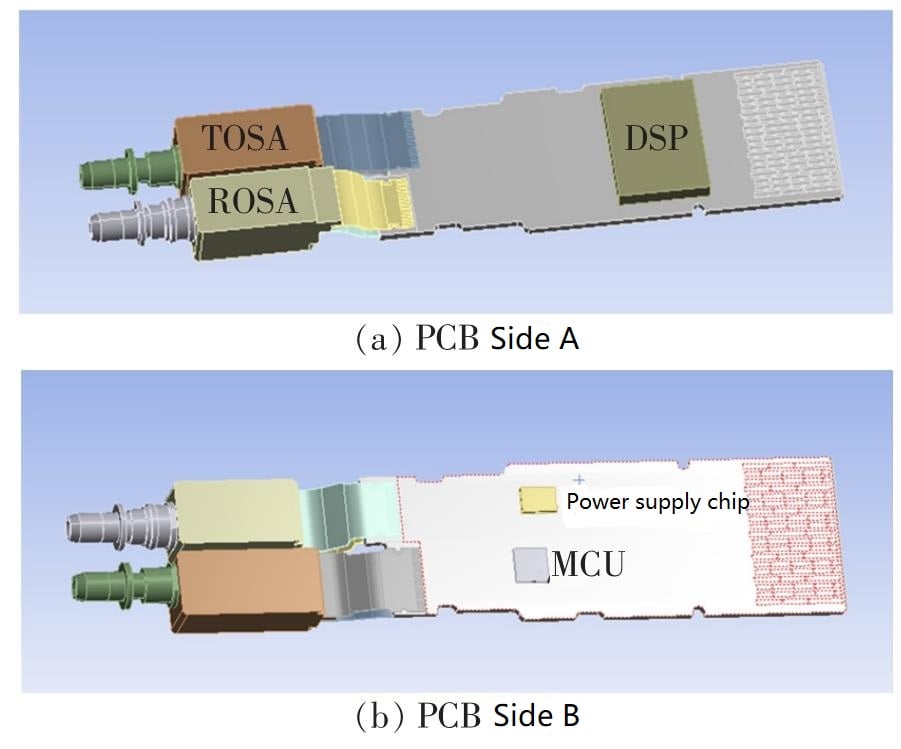
Figure 1: Thermal Simulation Model of 200G QSFP-DD LR4
The parameters related to the thermal analysis of each main component are given in Table 1 based on the measured results.
Table 1: Simulation parameters of main components
| Components | Thermal conductivity/W/m.K | Calorific value/W | Volume/cm³ | Heat liberation rate/W/cm³ |
|---|---|---|---|---|
| TOSA | 17.3 | 1.5 | 0.57 | 2.58 |
| ROSA | 17.3 | 1 | 0.53 | 1.87 |
| DSP | 124 | 7 | 0.25 | 2.76 |
| MCU | 124 | 0.3 | 0.0048 | 60.19 |
| Power supply chip | 124 | 0.3 | 0.0059 | 50.04 |
2 Simulation results
2.1 Temperature distribution inside the module
The temperature distribution inside the module at 70°C case temperature is shown in Figure 2, which is obtained by the thermal stability analysis method of the above model.
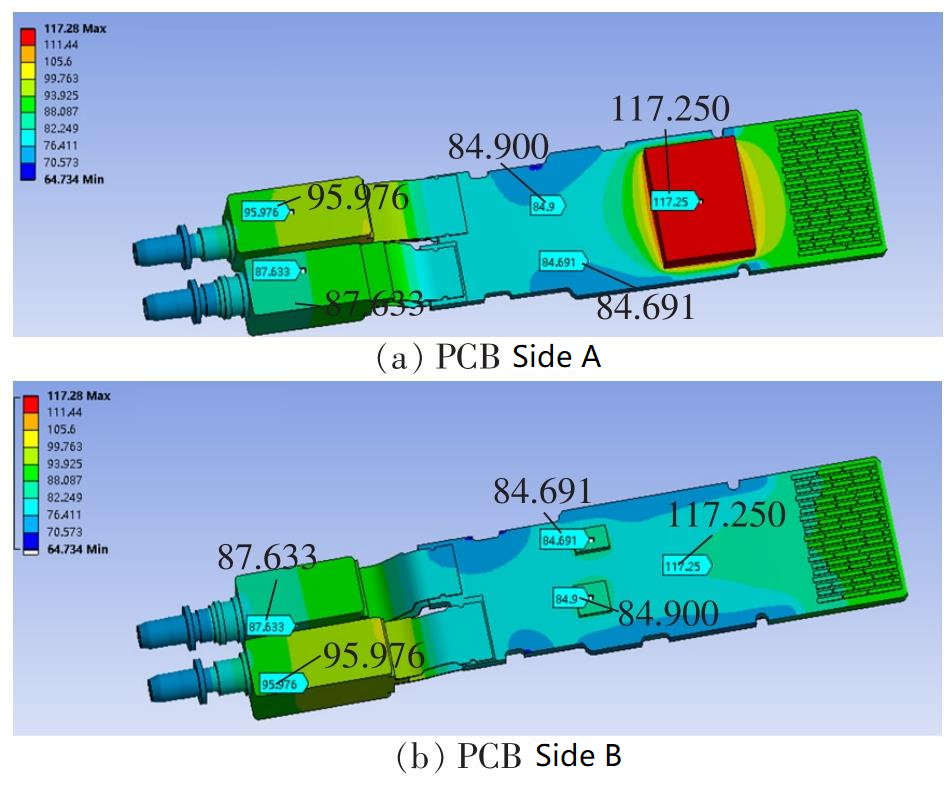
Figure 2: Internal temperature distribution of 200G QSFP-DD LR4 module at 70 °C case temperature
The temperatures of each major component are shown in Table 2.
Table 2 Temperature of each major device inside the 200GQSFP-DD LR4 module at 70 °C case temperature
| Components | TOSA | ROSA | DSP | MCU | Power supply chip |
|---|---|---|---|---|---|
| Temperature/°C | 95.9 | 87.6 | 117.3 | 84.9 | 84.7 |
As can be seen from Table 2, the temperature of most areas inside the module is much higher than 70°C at the internal steady state at the case temperature of 70°C. In order to ensure the electromagnetic compatibility (EMC) and electromagnetic interference (EMI) performance of the module, the inside of the module needs to be closed. For this reason, the inside of the module cannot have air for convection heat exchange like the instrument, that is to say, the main heat dissipation way of is heat conduction.
The module heating component can only conduct heat through the air, while the thermal conductivity of air is very low (0.03 W/m-K), which means that the heat generated by the components is difficult to dissipate in the small space inside the module. This is especially true for DSP. Its temperature rise exceeds 30 ℃ when the case temperature is at 70 ℃, which has exceeded the normal operating temperature range of the DSP. If the module is at such a high temperature for a long time, the normal operation of each component will be affected and even the device
If no measures are taken, the 200G QSFP-DD LR4 module has a great risk of failure at a high temperature of 70 ° C. Therefore, it is necessary to improve the heat dissipation conditions to effectively limit the temperature of each component to a safe range and ensure the normal operation of the optical module at a case temperature of 70 ° C for a long time.
2.2 Simulation of the improvement of heat dissipation by thermal conductive pads
Ceramic particle filled silicone film is a gap filling material with good thermal conductivity, often used as a thermal conductive pad to fill the gap between the heat generating component and the product case. In addition to good thermal conductivity, its good adhesion and compression properties can discharge the air between the heat generating device and the case, in order to achieve full contact and enhance the heat dissipation effect. With the increasing power consumption of optical modules, thermal conductive pads have been widely used to improve the heat dissipation conditions inside the modules.
The thermal pads are placed on the five major heat generating components as shown in Figure 3. The pads are placed on the upper surface of the DSP, MCU, power supply chip, and the upper and lower surfaces of the TOSA and ROSA, so that both sides of the pads are in contact with the component surfaces and the case, respectively, for the purpose of conducting the generated heat to the case. The thermal conductivity of the pad used in the simulation is 7 w, and the filling gap is 1 mm.
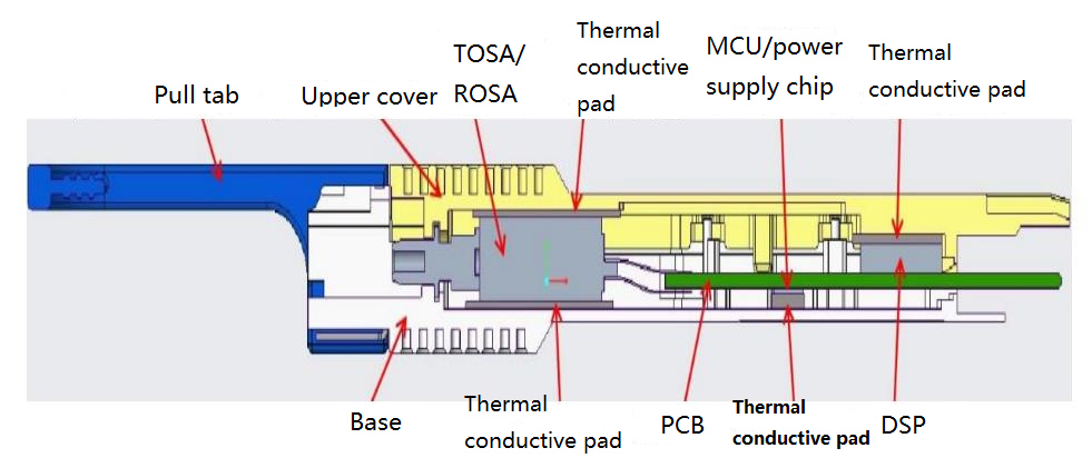
Figure 3: Schematic diagram of the thermal conductivity pad placed inside the module
The temperature distribution inside the module is shown in Figure 4. The comparison of the temperature of the main components with and without the thermal pad is shown in Fig. 5.
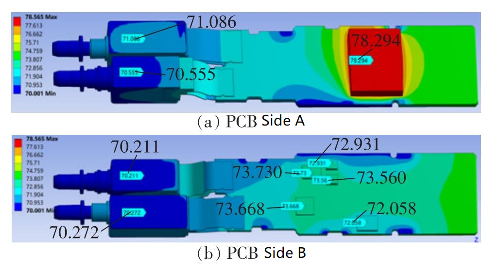
Figure 4: Temperature distribution inside the module after filling the thermal conductive pad
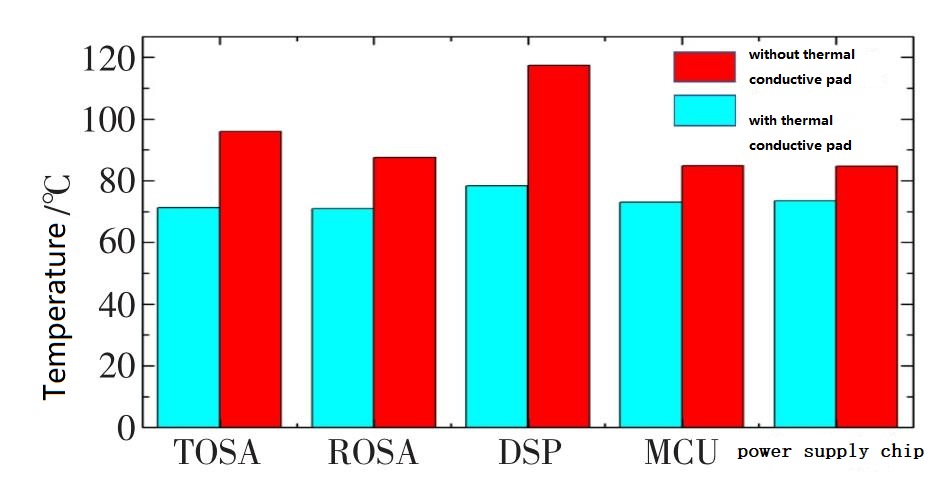
Figure 5: Comparison of the temperature of the main components inside the module before and after filling the thermal conductivity pad
As can be seen in Figure 5, after filling the thermal pad, the steady-state temperature of all major components drops significantly, with the temperature of the DSP chip dropping below 80°C and the temperature of the TOSA and ROSA devices falling to nearly 70°C, all in the normal operating temperature range. Therefore, filling the thermal pad can effectively improve the heat dissipation condition inside the module and guarantee the normal operation of each component under high temperature.
2.3 Effect of thermal conductivity pad coefficient on heat dissipation
Keeping other variables unchanged, change the thermal conductivity of the filled pad, and simulate the change of the internal temperature of the module when it is filled with pads with different thermal conductivity, as shown in Figure 6.
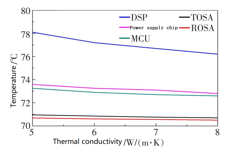
Figure 6: Temperature changes of the main components inside the module when it is filled with pads with different thermal conductivity
As can be seen from Figure 6, with the increase of the thermal conductivity of the heat conductive pad, the temperature of each heating element will decrease, especially for the device with large heat generation such as DSP, the cooling effect is more obvious. However, the relationship between temperature and the change of thermal conductivity of the thermal conductive pad is not linear, and the temperature decline range decreases with the increase of thermal conductivity.
2.4 Effect of filling gaps on the temperature of heating elements
Keeping the other variables unchanged, set the thermal conductivity of the thermal pad to 7 W/m·K. Change the gap between the surface of the heating element and the module case, and then simulate the change in the temperature distribution inside the module with different filling gaps, as shown in Figure 7.
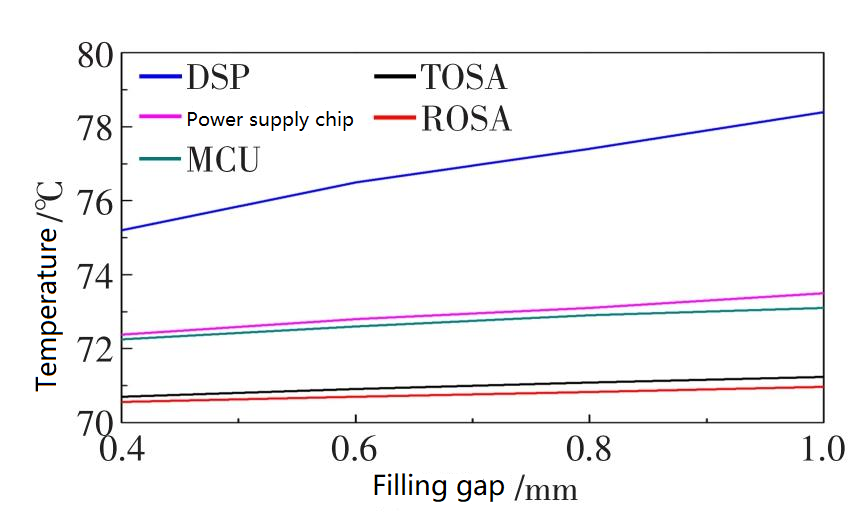
Figure 7: Temperature changes of the main components in the module under different filling gap conditions
It can be seen from the figure that with the increase of the filling gap, the temperature of each heating element will rise accordingly. Especially for devices with large heat generation such as DSP, the temperature rise effect is rather obvious. This is because the thermal conductivity of the chip and the shell is nearly 15 times that of the heat conductive pad. In the heat dissipation path of the heating element and the shell, the thicker the pad, the greater the thermal resistance, which in turn leads to a larger temperature rise. As shown in the figure, the filling gap and temperature are close to linear relationship, which is because the heat conductive pad completely covers the surface of the heating element, so that all the heat of the heating element is transferred to the shell through the heat conductive pad.
From the simulation results, it can be seen that heat conductive pads with higher thermal conductivity need to be used. However, the cost of heat conductive pad with high thermal conductivity is higher, and the material is hard and not easy to be compressed. Therefore, when selecting the thermal conductivity of the heat conductive pad, the heat-conducting property, material hardness and cost should be considered comprehensively. Although the smaller the filling gap, the lower the temperature rise, the design size of the gap should also consider the height error of the shell and the heating element and the appropriate compression rate of the heat conducting pad. In general, the compression rate of the thermal pad is maintained between 20% and 25% in the industry, which can not only ensure that the thermal pad can be completely filled in the gap, but also ensure that the device will not be affected by stress due to excessive compression of the thermal pad. Therefore, the general design size of the gap is 0.6 mm, filling 0.8 mm thermal pad.
3. Measured module performance
After optimizing the design, we used thermal conductive pads with a thermal conductivity of 7 w and a gap of 0.8 mm, which were attached to the main internal components of the module as shown in Figure 3. The transmitting and receiving performance of the module was tested at an ambient temperature of 70 °C as shown in Figure 8.
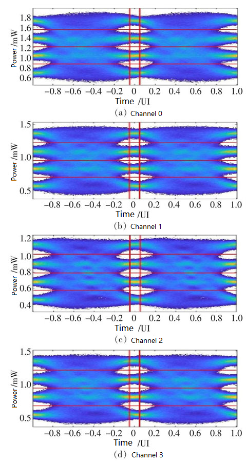
Figure 8: Eye Diagram of 200GQSFP-DD LR4 Optical Module at 70°C Measured
The main performance indicators of the module, including Transmitter Dispersion Eye Closure Quaternary (TDECQ), Extinction Ratio (ER) and Receiving Sensitivity, are shown in Table 3. All the indicators meet the requirements of the protocol, and the module can work normally at high temperature. At the same time, the power consumption of the optical module and the temperature measured by the built-in sensor are also tested. The measured temperature in the optical module is significantly higher than the ambient temperature. When the ambient temperature and the temperature of the module shell are 70°C, the temperature measured inside the module is about 76°C, indicating that the overall heat dissipation inside the module is good and the chips can maintain the normal working temperature.
Table 3 Main performance indicators of 200GQSFP-DD LR4 optical module measured at 70°C
| Channel-0 | Channel-1 | Channel-2 | Channel-3 | |
|---|---|---|---|---|
| TDECQ/dB | 2.944 | 2.737 | 2.598 | 2.439 |
| Extinction ratio/dB | 4.195 | 4.047 | 4.34 | 3.958 |
| Receiving sensitivity/dBm | -9.29 | -9.87 | -9.07 | -9.25 |
Table 4 Measured power consumption and internal temperature
| Ambient temperature/°C | 0 | 25 | 70 |
|---|---|---|---|
| Internal temperature of the module/℃ | 7.55 | 32.1 | 76.8 |
| Power consumption/W | 5.15 | 5.31 | 6.3 |
4. Conclusion
In practical application scenarios, the overall heat dissipation of the optical module is closely related to the internal environment and external environment of the module. Some research results show that the external structure and surrounding airflow of the optical module will affect the overall heat dissipation effect of the module, and then affect its stable operation.
This article mainly studies the influence of the environment on heat dissipation of optical module, especially the influence of various parameters of thermal conductive pad on the heat dissipation effect of 200G QSFP-DD LR4 optical module. It is verified that adding heat dissipation pad has obvious effect on reducing the internal temperature of QSFP-DD packaged optical module, and that the module meets the standard in the high temperature environment of 70°C. These results provide a thermal design reference for 200G QSFP-DD optical modules of various specifications, and can be extended to 400G or even 800G QSFP-DD optical modules, providing useful experience for the large-scale practical application of optical modules in QSFP-DD packaging form.
Related Products:
-
 NVIDIA(Mellanox) MMA1T00-HS Compatible 200G Infiniband HDR QSFP56 SR4 850nm 100m MPO-12 APC OM3/OM4 FEC PAM4 Optical Transceiver Module
$139.00
NVIDIA(Mellanox) MMA1T00-HS Compatible 200G Infiniband HDR QSFP56 SR4 850nm 100m MPO-12 APC OM3/OM4 FEC PAM4 Optical Transceiver Module
$139.00
-
NVIDIA(Mellanox) MMS1W50-HM Compatible 200G InfiniBand HDR QSFP56 FR4 PAM4 CWDM4 2km LC SMF FEC Optical Transceiver Module
$650.00
-
Cisco QDD-2X100-SR4-S Compatible 2X100G QSFP-DD SR4 850nm 70m/100m OM3/OM4 MPO-24(UPC) MMF Optical Transceiver Module
$350.00
-
Cisco QDD-2X100-CWDM4-S Compatible 2X100G QSFP-DD CWDM4 2km CS SMF Optical Transceiver Module
$1100.00
-
QSFP-DD-200G-CWDM4-10 2X100G QSFP-DD CWDM4 10km Dual CS SMF Optical Transceiver Module
$1300.00
-
QSFP-DD-200G-LR4 200G QSFP-DD LR4 PAM4 LWDM4 10km LC SMF FEC Optical Transceiver Module
$1000.00
-
QSFP-DD-200G-ER4 200G QSFP-DD ER4 PAM4 LWDM4 40km LC SMF FEC Optical Transceiver Module
$1500.00
-
NVIDIA(Mellanox) QMMA1U00-WS Compatible 400G QSFP-DD SR8 PAM4 850nm 100m MTP/MPO OM3 FEC Optical Transceiver Module
$149.00
-
Cisco QDD-400G-DR4-S Compatible 400G QSFP-DD DR4 PAM4 1310nm 500m MTP/MPO SMF FEC Optical Transceiver Module
$400.00
-
Cisco QDD-400G-LR4-S Compatible 400G QSFP-DD LR4 PAM4 CWDM4 10km LC SMF FEC Optical Transceiver Module
$600.00