A core switch is not a type of switch, but a switch placed at the core layer (the backbone of the network).
Generally, large-scale enterprise networks and Internet cafes need to purchase core switches to achieve strong network expansion capabilities to protect the original investment. When the number of computers reaches 50, these places may use core switches. A router is enough when the computers are less than 50. The so-called core switch is for the network architecture. If it is a small local area network with several computers, a small switch with 8 ports can be called a core switch.
Differences between the core switch and ordinary switch
-
The difference between ports
The number of standard switch ports is generally 24-48, and most network ports are Gigabit Ethernet or Fast Ethernet ports. The primary function is to access user data or aggregate some switch data at the access layer. This kind of switch can configure Vlan simple routing protocol and some simple SNMP functions, with relatively small backplane bandwidth.
-
The differences between connecting or accessing the network
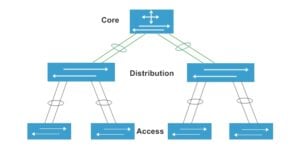
The part of the network that directly deals with users’ network connection or access is usually called the access layer, and the part between the access layer and the core layer is called the distribution layer or the aggregation layer. The purpose of the access layer is to allow end-users to connect to the network, so the access layer switch has the characteristics of low cost and high port density.
The aggregation layer switch is the aggregation point of multiple access layer switches, and it must be able to handle all traffic from the access layer devices and provide uplinks to the core layer. Therefore, the aggregation layer switches have higher performance, fewer interfaces, and higher switching rates.
The main part of the network is called the core layer. The main purpose of the core layer is to provide an optimized and reliable backbone transmission structure through high-speed forwarding of communication. Therefore, the core layer switch application has higher reliability, performance, and throughput.
Different layers of the network
Advantages of Core Switches
Compared with ordinary switches, data center switches need to have the following characteristics: large cache, high capacity, virtualization, FCoE, Layer 2 TRILL technology, scalability, and module redundancy.
-
Large cache technology
The data center switch has changed the outgoing port caching method of the traditional switch. It adopts a distributed cache architecture, and the cache is much larger than that of the ordinary switch. The cache capacity can reach more than 1G, while the general switch can only reach 2-4m. For each port, the burst traffic cache capacity can reach 200ms under the condition of 10 Gigabit full line speed, so that in the case of burst traffic, the large cache can still ensure zero packet loss in network forwarding, which is just suitable for a large number of servers in the data center and the burst traffic.
-
High-capacity equipment
The network traffic in the data center has the characteristics of high-density application scheduling and surge burst buffering. However, ordinary switches can not achieve accurate identification and control of services with the purpose of interconnection. Neither can they achieve rapid response and zero packet loss, so business continuity cannot be guaranteed. The reliability of the system mainly depends on the reliability of the equipment.
Therefore, ordinary switches cannot meet the needs of data centers. Data center switches need to have high-capacity forwarding characteristics and support high-density 10-Gigabit boards, that is, 48-port 10-Gigabit boards. For forwarding, data center switches can only use the CLOS distributed switching architecture.
In addition, with the popularity of 40G and 100G, 40G boards supporting 8 ports and 100G boards supporting 4-port are gradually becoming commercially available. Besides, 40G and 100G boards for data center switches have already entered the market, thus meeting the demand for high-density applications in data centers.
-
Virtualization technology
The network equipment in the data center needs to have the characteristics of high management and high security and reliability. Therefore, the switches in the data center also need to support virtualization. Virtualization is to transform physical resources into logically manageable resources to break the barriers of physical structure.
Using virtualization technology, multiple network devices can be managed in a unified manner. Services on a single device can be completely isolated, which can reduce management costs of the data center by 40% and increase IT utilization by approximately 25%.
virtualization technology
-
TRILL technology
In terms of building a Layer two network in the data center, the original standard is the FTP protocol. But it has the following defects:
– STP works through port blocking, and all redundant links do not forward data, resulting in a waste of broadband resources.
– The network has only one spanning tree, and data packets must pass through the root bridge, which affects the forwarding efficiency of the entire network.
Therefore, STP will no longer be suitable for the expansion of super-large data centers. TRILL comes into being to make up for these defects of STP. The TRILL protocol effectively combines Layer 2 configuration and flexibility with Layer 3 convergence and scale. The entire network can be forwarded without loops without the need for configuration at the second layer. TRILL technology is a basic Layer 2 feature of data center switches, which is not available in ordinary switches.
-
FCoE technology
Traditional data centers often have a data network and a storage network. The emergence of FCOE technology makes network convergence possible. FCoE is a technology that encapsulates data frames of a storage network in Ethernet frames for forwarding. The realization of this fusion technology must take place on the switches of the data center, and ordinary switches generally do not have these functions.
Functions such as link aggregation, redundancy, stacking, and hot backup are also very important, which determine the performance, efficiency, and stability of core switches in practical applications.
Link Aggregation
Link aggregation is the combination of two or more data channels into a single channel that appears as a higher-bandwidth logical link. Link aggregation is generally used to connect one or more devices with high bandwidth requirements, such as servers or server farms connected to a backbone network. It can be used to extend link bandwidth and provide higher connection reliability.
For example, the company has two floors, which run different businesses. The networks on the two floors were separate originally, but it is inevitable that the same company would have interaction. At this time, we can open up the network between the two floors, so that the departments with a mutual connection can communicate with each other at a high speed. As shown below:
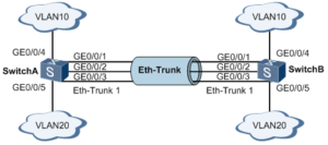
An Eth-Trunk interface to connect switch A and switch B
As shown in the figure above, SwitchA and SwitchB are connected to VLAN10 and VLAN20 networks respectively through Ethernet links, and there is a large amount of data traffic between SwitchA and SwitchB.
The user expects that a larger link bandwidth can be provided between SwitchA and SwitchB so that the same VLANs can communicate with each other. Meanwhile, users also hope to provide a certain degree of redundancy to ensure the reliability of data transmission and links.
Create an Eth-Trunk interface and add member interfaces to increase the link bandwidth. Two switches are configured with Eth-Trunk1, and then the ports of the three lines that need to communicate are added to Eth-Trunk1, and the port trunk is set to allow the corresponding VLAN to pass through. In this way, the network on the two floors can communicate normally.
Link redundancy
In order to maintain the stability of the network, in a network environment composed of multiple switches, some backup connections are used to improve the efficiency and stability of the network. The backup connections here are also called backup links or redundant links.
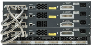
Stacking of switches
Connected via proprietary stacking cables, multiple switches can be stacked into a single logical switch. All switches in this logical switch share the same configuration and routing information. The performance of a logical switch will not be affected as an individual switch is added and removed.
The types of switch optical ports include SFP, 10G SFP+, 25G SFP28, 40G QSFP+, 100G QSFP28, etc. We need to select the right optical module to insert into the switch for normal use. For example, SFP ports can be inserted into SFP optical modules, and 10G SFP+ ports are for 10G optical modules. 100G QSFP28 port needs to be inserted into 100G QSFP28 optical modules.
If we want to interconnect a switch with an electrical port and a switch with an optical port, we can use Copper SFP. It is used to convert the optical port into an electrical port so that we can use a network cable to connect the two switches.
The stacked switches are connected by two loops. The hardware of the switch is responsible for load balancing the data packets on the dual loops. The loop acts as the backplane of this large logical switch. When both loops are working normally, the transmission rate of data packets on this logical switch is 32Gbps.
When a data frame needs to be transmitted, the switch’s software will calculate which loop is more available, and then the data frame will be sent to that loop. If a stacking cable fails, the switches at both ends of the failed cable will detect the failure and disconnect the affected loop, while the logical switch can still work at a single loop state with a packet throughput rate of 16Gbps. The switches are stacked in a daisy-chain manner. Refer to the following figure for the connection method.
The switches are stacked in a daisy-chain manner
Stacking increases the stability of switch ports and bandwidth.
Hot Backup (HSRP)
The core switch is the core and heart of the entire network. If a fatal failure of the core switch occurs, the local network will be paralyzed, which causes inestimable loss. Therefore, when we choose core switches, we often see that some core switches are equipped with functions such as stacking or hot backup.
Using hot backup for core switches is an inevitable choice to improve network reliability. When a core switch cannot work at all, all its functions are taken over by another backup router in the system until the router in question returns to normal. This is the Hot Standby Router Protocol (HSRP).
The condition for realizing HSRP is that there are multiple core switches in the system, and they form a “hot backup group”, which forms a virtual router. At any time, only one router in a group is active, and it forwards data packets. If the active router fails, a backup router will be selected to replace the active one, but the host in the network treats the router as not changed. Therefore, the host remains connected and is not affected by the failure, which better solves the problem of core switch switching.
To reduce network data traffic, after the active core switch and the backup core switch are set, they regularly send HSRP packets. If the active core switch fails, the backup core switch takes over as the active core switch. If the backup core switch fails or becomes the active core switch, another core switch will be selected as the backup core switch.
When the line from an access layer switch to the main core switch fails, it switches to the standby machine.
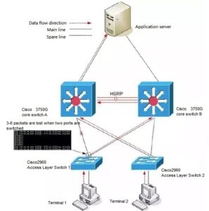
Scenario one of data link failure
When the data link of the access layer switch 1 connected to the core switch A fails, the data link of the access layer switch 1 is switched to the core switch B, but during the switching period, the access layer switch 1 loses six data packets, as shown in the above.
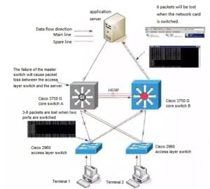
Scenario two of data link failure
When the main link between the server and the core switch A fails (such as line, network card, etc.), and when the main network card of the server is switched to the standby network card, six data packets will be lost. But when the main link is restored, the server will automatically switch from the standby network card to the main network card, and data packets will not lose during this switch.
Related Products:
-
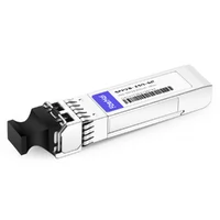
 Cisco SFP-25G-SR-S Compatible 25G SFP28 SR 850nm 100m LC MMF DDM Transceiver Module
$25.00
Cisco SFP-25G-SR-S Compatible 25G SFP28 SR 850nm 100m LC MMF DDM Transceiver Module
$25.00
-
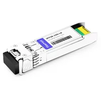
Cisco SFP-10/25G-LR-S Compatible 25G SFP28 LR 1310nm 10km LC SMF DDM Transceiver Module
$45.00
-
Cisco QSFP-40G-CSR4 Compatible 40G QSFP+ CSR4 850nm 400m MTP/MPO MMF DDM Transceiver Module
$30.00
-
Cisco WSP-Q40GLR4L Compatible 40G QSFP+ LR4L 1310nm (CWDM4) 2km LC SMF DDM Transceiver Module
$129.00
-
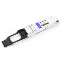
Cisco QSFP-100G-SR4-S Compatible 100G QSFP28 SR4 850nm 100m MTP/MPO MMF DDM Transceiver Module
$40.00
-
Cisco QSFP-100G-CWDM4-S Compatible 100G QSFP28 CWDM4 1310nm 2km LC SMF DDM Transceiver Module
$110.00
-
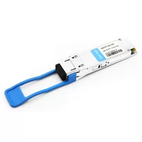
Cisco QSFP-100G-LR4-S Compatible 100G QSFP28 LR4 1310nm (LAN WDM) 10km LC SMF DDM Transceiver Module
$285.00
-
Cisco QSFP-100G-ZR4-S Compatible 100G QSFP28 ZR4 1296-1309nm LWDM 80km LC SMF DDM Transceiver Module
$1500.00
-
QSFP-DD-400G-SR8 400G QSFP-DD SR8 PAM4 850nm 100m MTP/MPO OM3 FEC Optical Transceiver Module
$149.00
-
QSFP-DD-400G-DR4 400G QSFP-DD DR4 PAM4 1310nm 500m MTP/MPO SMF FEC Optical Transceiver Module
$400.00
-
QSFP-DD-400G-SR4.2 400Gb/s QSFP-DD SR4 BiDi PAM4 850nm/910nm 100m/150m OM4/OM5 MMF MPO-12 FEC Optical Transceiver Module
$900.00
-
QSFP-DD-400G-FR4 400G QSFP-DD FR4 PAM4 CWDM4 2km LC SMF FEC Optical Transceiver Module
$500.00
-
QSFP112-400G-SR4 400G QSFP112 SR4 PAM4 850nm 100m MTP/MPO-12 OM3 FEC Optical Transceiver Module
$450.00
-
QSFP112-400G-DR4 400G QSFP112 DR4 PAM4 1310nm 500m MTP/MPO-12 with KP4 FEC Optical Transceiver Module
$850.00