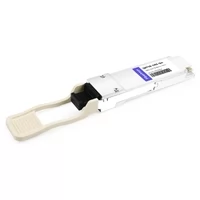
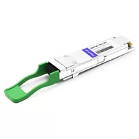
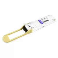
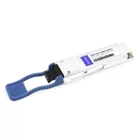
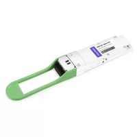
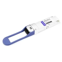
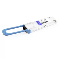
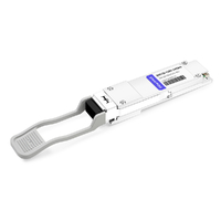
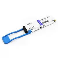
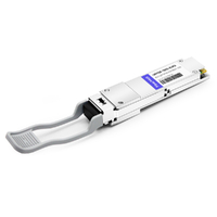
A network team I know designed a perfect 16-rack spine-leaf fabric on paper. They counted every port, priced every switch, and presented the BOM to their director with confidence. On installation day, they discovered they were eight ports short. Breakout cables had consumed uplink ports they’d counted as spine connections. The project stalled for three weeks while they reordered hardware.
100g network design with QSFP28 isn’t hard. It’s just unforgiving about details most guides skip. This article gives you the actual math, module choices, and build sheets we use when planning real fabrics. No generic topology explanations. No hand-waving about “choose the right optic.” Just the numbers that matter, with enough context to adapt them to your deployment.
If you need a grounding in QSFP28 itself — form factors, electrical specs, speed lanes — start with our complete QSFP28 guide. The rest of this article assumes you know what a QSFP28 module is and focuses on where to put it in your fabric.

Spine-Leaf Architecture: The 5-Minute Primer
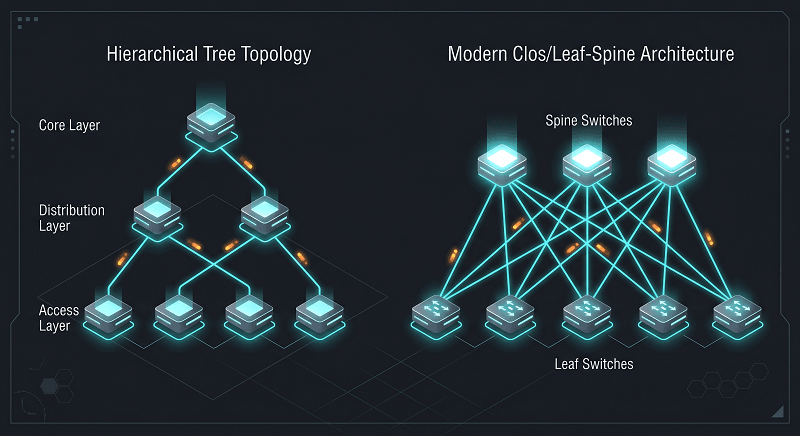
Three-tier designs — core, distribution, access — dominated enterprise networking for two decades. They worked fine when most traffic flowed north-south: users in cubicles hitting servers in a data hall. But virtualization, distributed storage, and container orchestration flipped the traffic pattern. Now most packets travel east-west: server to server, rack to rack, leaf to leaf.
Spine-leaf solves this with a two-tier Clos topology. Every leaf switch connects to every spine switch. No inter-leaf links. No aggregation layer. Traffic between any two racks always traverses leaf → spine → leaf. That means predictable latency — one hop to the spine, one hop back — and no Spanning Tree Protocol blocking ports.
ECMP (Equal-Cost Multi-Path) routing makes this efficient. With four spines, a leaf has four equal-cost paths to any destination. All paths stay active. If one spine fails, traffic redistributes across the remaining three. No convergence delay. No blocked bandwidth.
| Factor | 3-Tier | Spine-Leaf |
| Tiers | Core/Distribution/Access | Spine/Leaf only |
| Latency | Variable | Predictable (1-2 hops) |
| Scale | Vertical | Horizontal |
| Traffic Optimized | North-South | East-West |
| Protocol | STP (blocking) | ECMP (all paths active) |
| Typical Use | Legacy enterprise | Modern data center |
The trade-off? More fiber. A 16-leaf fabric with 4 spines needs 64 leaf-to-spine links. That’s 64 QSFP28 modules and a lot of MPO trunks. But every link carries traffic, nothing sits blocked, and scaling means adding more spines or leaves — not ripping out your core.
Where QSFP28 Fits in the Topology
QSFP28 occupies three distinct roles in a spine-leaf fabric. Getting the module type wrong for any of them costs money, power, or both.
Leaf-to-spine uplinks run at native 100G. These are the fabric’s backbone. You want the cheapest module that reliably covers the distance.
For most intra-data-center runs under 100 meters, that’s QSFP28 SR4 over OM4 MPO. For inter-hall links stretching 500 meters to 2 kilometers, CWDM4 over single-mode LC fiber becomes the better choice. LR4 only makes sense when you genuinely need 10 kilometers — typically spine-to-core or DCI scenarios.
Leaf-to-server connections usually break out. While AI and HPC workloads have moved to native 100G or 400G, most general compute servers in 2026 still default to 25G NICs. A QSFP28 port on a leaf switch can split into four 25G SFP28 channels using a breakout DAC or AOC cable. One QSFP28 port feeds four servers. This is where the port-count surprises start. More on that in the breakout section below.
Spine-to-core or DCI needs reach. When your spine connects to a campus core or a WAN edge, distances exceed what SR4 or CWDM4 can handle. That’s the legitimate home for LR4.
The mistake we see repeatedly? Using LR4 everywhere because “it works for all distances.” It does. It also costs 3-4x more per module and burns an extra watt of power. A team I worked with saved $38,400 by switching 160 intra-DC links from LR4 to CWDM4. The links performed identically. The CFO noticed.
| Network Tier | Typical Distance | Recommended Module | Fiber Type |
| Leaf-to-Server (breakout) | 1-7m | QSFP28 to 4xSFP28 DAC | Copper |
| Leaf-to-Server (breakout) | 7-100m | QSFP28 to 4xSFP28 AOC | MMF |
| Leaf-to-Spine (intra-DC) | 100-500m | QSFP28 SR4 | OM4 MPO |
| Leaf-to-Spine (inter-hall) | 500m-2km | QSFP28 CWDM4 | SMF LC |
| Spine-to-DCI/Campus | 2-10km | QSFP28 LR4 | SMF LC |
For a deeper comparison of SR4, LR4, CWDM4, and PSM4 — wavelengths, power budgets, link margins — see our QSFP28 module types explained guide.
Oversubscription: The Math That Matters
Oversubscription is the ratio between total downstream bandwidth (leaf to server) and total upstream bandwidth (leaf to spine). It answers one question: if every server tries to transmit at full speed simultaneously, how much contention occurs at the uplink?
The formula is simple:
Oversubscription Ratio = Total Downlink Bandwidth / Total Uplink Bandwidth
Simple. But painful to get wrong.
A leaf switch with 48x 25G server ports and 6x 100G spine uplinks carries 1,200 Gbps of downlink capacity and 600 Gbps of uplink capacity. That’s a 2:1 ratio. In practice, most traffic patterns never saturate all downlinks at once, so 2:1 or 3:1 works fine for general compute.
But ratios change when a spine fails. With four spines and 6x100G uplinks per leaf, each spine normally handles 150 Gbps of traffic. Lose one spine, and your total uplink capacity drops from 600 Gbps to 450 Gbps effective. Your 2:1 ratio becomes 2.7:1. If you designed for 3:1, N-1 pushes you to 4:1. That’s where congestion shows up during backup windows or flash events.
| Workload | Target Ratio | Example Config | Notes |
| AI/ML / HPC | 1:1 (non-blocking) | 32x100G down + 32x100G up | RDMA sensitive |
| Storage / NVMe-oF | 1:1 to 2:1 | 24x25G + 4x100G up | Low latency critical |
| General VMs / Compute | 2:1 to 3:1 | 48x25G + 6x100G up | Industry standard |
| Web / Low bandwidth | 3:1 to 4:1 | 48x10G + 4x100G up | Cost optimized |
| Dev/Test | 4:1+ | 48x10G + 3x100G up | Non-critical |
Arista’s field engineers recommend starting at 3:1 for general compute, measuring actual uplink utilization for 90 days, then adjusting. Consistently above 60%? Add a spine. Below 30%? You over-provisioned. The ratio isn’t a religious doctrine — it’s a starting point you validate with real telemetry.
Three Complete Build Sheets
Below are fabric designs for three common scales. Each includes switch specifications, module counts, cable types, and oversubscription ratios. Use them as starting points, not gospel.
Small Fabric: 8 Racks, 384 Servers
This fits a mid-size data hall or a dedicated private cloud pod. Two spines give you redundancy without complexity.
| Component | Specification | Count | Notes |
| Spine Switches | 32x100G QSFP28 | 2 | e.g., Arista 7060X, Cisco N9K |
| Leaf Switches | 48x25G + 6x100G | 8 | Top-of-rack |
| Server Connections | 25G SFP28 DAC | 384 | 1-3m per rack |
| Leaf-to-Spine | QSFP28 SR4 | 16 | OM4 MPO trunks |
| Breakout Cables | QSFP28→4xSFP28 DAC | 0 | Native 25G ports used |
| Oversubscription | 2:1 | — | 1,200G down / 600G up |
| ECMP Paths | 2-way | — | Add 3rd spine for N+1 |
Total QSFP28 modules: 16 (all SR4). Optical power draw: roughly 48W. Standard row cooling handles this without drama.
Medium Fabric: 16 Racks, 768 Servers
This is where full ECMP starts to shine. Four spines give 4-way load balancing and genuine N-1 resilience.
| Component | Specification | Count | Notes |
| Spine Switches | 32x100G QSFP28 | 4 | Full ECMP |
| Leaf Switches | 48x25G + 6x100G | 16 | — |
| Server Connections | 25G SFP28 DAC | 768 | — |
| Leaf-to-Spine | QSFP28 SR4/CWDM4 | 64 | SR4 for <100m, CWDM4 beyond |
| Oversubscription | 2:1 | — | N-1: 2.7:1 |
| ECMP Paths | 4-way | — | Best balance |
Total QSFP28 modules: 64. Mix SR4 for short intra-row runs and CWDM4 for anything crossing a meet-me room. At this scale, cable management becomes a project in itself — plan your MPO trunk routing before rack installation, not after.
Large Fabric: 32 Racks, 1,536 Servers
At 32 leaves, you’ve hit the practical limit of a single spine-leaf pod for most switch platforms. ECMP path counts vary by vendor — Arista supports up to 128, Juniper QFX10002 supports 64 next-hops — but building fabrics beyond 32 spines introduces immense cabling complexity and diminishes the return on investment.
For a 32-leaf fabric, you’ll generally want 8-16 spines depending on your oversubscription target. Leaves should upgrade to 48x25G + 8x100G to keep ratios reasonable. Total QSFP28 count: roughly 192 for leaf-to-spine plus spares. Consider QSFP-DD spines for 400G uplink capability if you plan to grow beyond this pod in the next two years.
MPO trunk cabling at this scale means 2-4 MPO trunks per leaf-to-spine pair. That’s 384-768 MPO connectors in your fiber plant. Label everything. Document everything. The technician who installs this won’t be the one who troubleshoots it at 2 AM.
For current module pricing by type and volume, see our QSFP28 pricing analysis.
Breakout Economics: 4x25G vs Native 100G
Breakout cables are the hidden variable in leaf switch port planning. A leaf advertises “6x100G uplinks” but if you’re using breakout for server-facing ports, some of those 100G ports get consumed serving 25G NICs.
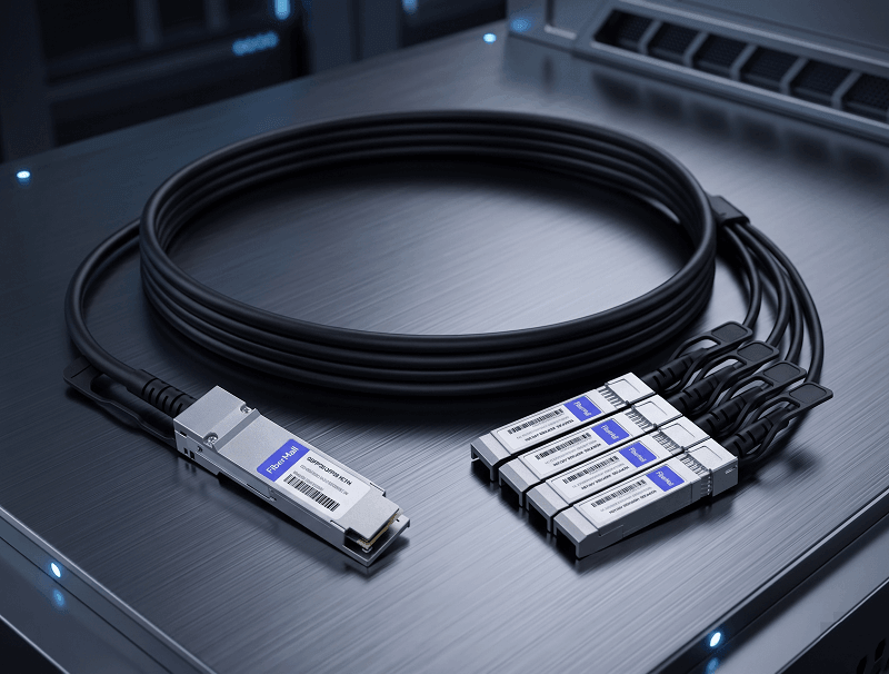
Here’s the reality: a leaf with 48x25G native SFP28 ports plus 6x100G QSFP28 uplinks doesn’t need breakout at all. But many switches — especially cost-optimized models — ship with fewer native 25G ports and expect you to break out QSFP28 ports for server connectivity. A 32x100G leaf, for example, might break out 16 of those ports to serve 64 servers at 25G, leaving only 16 ports for spine uplinks.
| Factor | Breakout (4x25G) | Native 100G |
| Server bandwidth | 25G per server | 100G per server |
| Leaf uplinks consumed | 1 per 4 servers | 1 per 1 server |
| Cable type | QSFP28→4xSFP28 DAC/AOC | QSFP28 DAC/AOC or fiber |
| Cost per server | Lower | Higher |
| Future upgrade | Easy (replace breakout cable) | Requires new NIC + cable |
| Best for | General compute, web | GPU, storage, HPC |
The math is brutal.
The classic mistake: planning 6x100G uplinks per leaf for 4 spines, then discovering you need 2 of those uplinks for breakout to servers. You’re left with 4 spine-facing ports, not 6. Your oversubscription math collapses. Your ECMP path count drops. And you’re back to the VAR quoting more switches.
Our advice? Count breakout ports first. Whatever remains goes to spine uplinks. Then run the oversubscription formula. Working backwards from “I need 6 spine uplinks” is how teams end up eight ports short on delivery day.
Thermal and Power Planning
QSFP28 modules don’t just cost money. They generate heat. A lot of it, in aggregate. Most engineers budget for switch power draw from the spec sheet but forget to add optical module load on top.
SR4 modules draw roughly 2.5-3.5W each. CWDM4 runs 3.5-4.5W. LR4 can hit 4.5W per module. That sounds trivial until you multiply by 32 ports in a dense spine switch. Thirty-two LR4 modules add 144W of optical heat to a platform already running 400-500W for switching silicon and fans.
| Fabric Size | Total QSFP28 Count | Optical Power | Cooling Required |
| Small (8 leaf, 2 spine) | ~40 modules | ~160W | Standard row |
| Medium (16 leaf, 4 spine) | ~96 modules | ~400W | Enhanced airflow |
| Large (32 leaf, 8 spine) | ~224 modules | ~950W | Dedicated cooling |
Heat sneaks up on you.
A fully-loaded 32-port QSFP28 spine with LR4 modules hit thermal alarms during a summer heatwave at a site I visited. Ambient crept to 28°C. The switch’s internal sensors tripped at 52°C and started throttling ports. The team had to install row coolers and re-rack with blanking panels to force airflow through the chassis, not around it. The fix worked, but the three-day outage wasn’t on anyone’s project plan.
The lesson: plan your cooling for summer peak, not winter baseline. And ask your module supplier for actual power draw, not datasheet maximums. FiberMall tests and publishes typical power consumption for every QSFP28 variant — the difference between “up to 4.5W” and “typically 3.8W” matters when you’re multiplying across hundreds of modules.
Need help calculating thermal load for your specific fabric? Contact our engineers for a power and cooling review.

Scaling Beyond 100G: The 400G Migration Path
Spine-leaf fabrics don’t get ripped out and replaced. They evolve. The standard migration path starts at the spine layer: upgrade spines to 400G while keeping 100G leaf uplinks. This gives you 4x the fabric bandwidth without touching your server connections.
QSFP-DD ports accept QSFP28 modules. That’s the critical backward compatibility that makes phased upgrades practical. Install QSFP-DD spines today, populate them with QSFP28 LR4 or CWDM4 for your 100G leaves, and replace the optics with 400G modules when you’re ready. No switch swap required.
The hybrid approach — 400G at spine, 100G at leaf — is what most large data centers run in 2026. It balances capacity against cost. 400G optics are still 2-3x the price of QSFP28, so you only deploy them where link aggregation would otherwise force you to add more spines.
When should you make the jump? Our rule of thumb: when your spine uplink utilization consistently exceeds 70% during normal operations, or when adding another 100G spine exceeds your ECMP path limit. Until then, a well-designed 100G fabric with 2:1 or 3:1 oversubscription has plenty of headroom.
FAQ
What oversubscription ratio should I use for 100G spine-leaf?
Start with 3:1 for general compute, 2:1 for storage, and 1:1 for AI/HPC or RDMA workloads. Measure actual utilization for 90 days and adjust by adding spines if uplinks stay above 60%.
How many spine switches do I need?
Minimum two for redundancy. Most fabrics run 4 spines up to 16-24 leaves. Beyond 32 leaves, check your switch’s ECMP limit — typically 16-64 next-hop paths. Dual-homed servers consume two paths per flow.
Should I use QSFP28 SR4 or CWDM4 for leaf-to-spine?
SR4 for anything under 100 meters on OM4 MPO. CWDM4 for 100 meters to 2 kilometers on single-mode LC. LR4 only when you need 10km reach or have genuinely bad fiber with high loss.
Can I use breakout cables for server connections in spine-leaf?
Yes, and most fabrics do. QSFP28 to 4xSFP28 breakout DAC or AOC cables are standard for 25G server connections. Just remember: breakout ports consume QSFP28 ports you might have planned for spine uplinks.
How much power do QSFP28 modules consume?
SR4: 2.5-3.5W. CWDM4: 3.5-4.5W. LR4: 4.0-4.5W. In a 32-port spine, that’s 80-144W of optical heat alone. Factor this into your rack power budget and cooling design.
When should I upgrade from 100G to 400G spine links?
When spine uplink utilization exceeds 70% consistently, or when you’ve reached your platform’s ECMP path limit and can’t add more 100G spines. QSFP-DD spines with QSFP28 optics today let you migrate to 400G later without replacing switches.
Conclusion
Designing a 100G spine-leaf fabric with QSFP28 comes down to a handful of decisions most guides gloss over. Get the module type right for each tier — SR4 inside the data hall, CWDM4 for longer runs, LR4 only when necessary.
Account for breakout ports before you count spine uplinks. Run the N-1 oversubscription math before you buy. And size your cooling for the optical heat load, not just the switch chassis.
The teams that get into trouble aren’t the ones who don’t understand spine-leaf topology. They’re the ones who designed it on paper and trusted the paper. Real fabrics have constraints — port counts, power budgets, cable management, thermal limits — that only show up when you spec the details.
If you’re planning a fabric and want a second set of eyes on the module selection, oversubscription math, or thermal load, talk to our engineering team. We’ve reviewed hundreds of these designs. The port-count surprises get old. We’d rather catch them on paper than on installation day.
For the broader picture on QSFP28 — speeds, compatibility, form factor comparisons — our complete QSFP28 guide covers the fundamentals this article assumed you knew.
Related Products:
-
 QSFP28-100G-SR4 100G QSFP28 SR4 850nm 100m MTP/MPO MMF DDM Transceiver Module
$40.00
QSFP28-100G-SR4 100G QSFP28 SR4 850nm 100m MTP/MPO MMF DDM Transceiver Module
$40.00
-
QSFP28-100G-IR4 100G QSFP28 IR4 1310nm (CWDM4) 2km LC SMF DDM Transceiver Module
$110.00
-
QSFP28-100G-DR1 100G QSFP28 Single Lambda DR 1310nm 500m LC SMF with FEC DDM Optical Transceiver
$180.00
-
QSFP28-100G-PSM4 100G QSFP28 PSM4 1310nm 500m MTP/MPO SMF DDM Transceiver Module
$180.00
-
QSFP28-100G-FR1 100G QSFP28 Single Lambda FR 1310nm 2km LC SMF with FEC DDM Optical Transceiver
$215.00
-
Arista Networks QSFP-100G-LRL4 Compatible 100G QSFP28 LRL4 1310nm (LWDM4) 2km LC SMF DDM Transceiver Module
$245.00
-
QSFP28-100G-LR1 100G QSFP28 Single Lambda LR 1310nm 10km LC SMF with FEC DDM Optical Transceiver
$265.00
-
QSFP28-100G-SR1.2 Single Rate 100G QSFP28 BIDI 850nm & 900nm 100m LC MMF DDM Optical Transceiver
$280.00
-
QSFP28-100G-LR4 100G QSFP28 LR4 1310nm (LAN WDM) 10km LC SMF DDM Transceiver Module
$285.00
-
QSFP28-100G-SWDM4 100G QSFP28 SWDM4 850nm-940nm 100m LC MMF DDM Optical Transceiver
$300.00
-
QSFP28-100G-LR4-20 100G QSFP28 LR4 1310nm LWDM4 20km LC SMF DDM Transceiver Module
$300.00
-
QSFP28-100G-BDRX 100G QSFP28 BIDI 850nm & 900nm Only Receiver 100m LC MMF Optical Transceiver
$379.00
-
QSFP28-100G-SRBD Dual Rate 40G/100G QSFP28 BIDI 850nm & 900nm 100m LC MMF DDM Optical Transceiver
$449.00
-
QSFP28-100G-ER1 100G QSFP28 ER1 Single Lambda 1310nm 40km PAM4 LC SMF DDM Transceiver Module
$1250.00