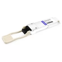
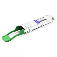
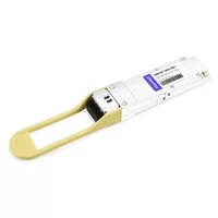
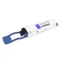
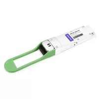
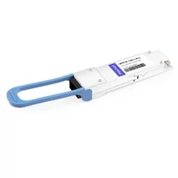
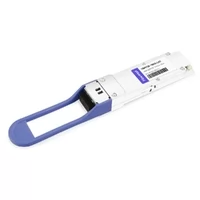
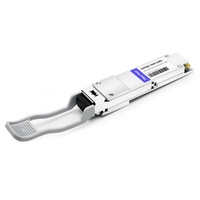
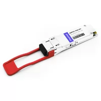
The PDU tripped at 11:47 AM on a Tuesday.
Not during burn-in. Not during failover testing. During a routine firmware update on a switch rack that had been running fine for six months.
The data center team in Hong Kong had sized the rack perfectly. Or so they thought.
Each switch base load was around 450W. The rack PDU was rated for 6kW. Plenty of headroom, right?
They had forgotten to account for 512 QSFP28 LR4 modules drawing roughly 4.5W each. That was 2,304W of optics power alone. Add the base load from eight fully populated QSFP28 switches, and the rack was pulling close to 5,900W before transient load, fan ramp-up, or future expansion.
No 80% planning margin. No room for power spikes. The breaker did not hesitate.
Four days of production delay. All because the power budget math skipped a line.
QSFP28 power consumption is not a spec-sheet curiosity. It is a rack design constraint that determines PDU sizing, cooling capacity, and whether your deployment stays stable in summer heat. This guide gives you the per-module wattage data, the switch-level math, and the thermal framework to plan it right the first time.
New to QSFP28? Our complete QSFP28 guide covers form factor basics, module types, and compatibility.
QSFP28 Power Consumption by Module Type
Not all QSFP28 modules draw the same power. The difference between a short-reach SR4 module and a long-reach ZR4 module can be close to 2x — and that gap matters when you are filling 32, 48, or 64 ports per switch.
More reach usually means more watts.
SR4 uses VCSEL arrays and PIN photodetectors. LR4 adds wavelength multiplexing and higher-performance single-mode optics. ER4 and ZR4 require stronger link-budget engineering, more sensitive receivers, FEC in many implementations, and in some designs optical amplification or higher-power optical components.
Each step up in reach and optical complexity adds heat.
Multimode Modules (SR4, BiDi)
SR4 and BiDi modules are among the lower-power options in the QSFP28 family. VCSEL-based multimode optics generally run cooler than long-reach single-mode designs.
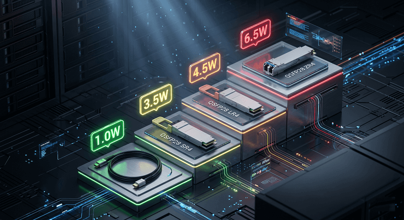
SR4: 3.0-3.5W typical, 3.5W max
BiDi: 3.0-3.5W typical
Best for: Data center spine-leaf links under 100m
If every link in your rack is SR4, you’re looking at the lowest possible optics power draw. Pretty straightforward.
Single-Mode Modules (LR4, CWDM4, PSM4)
Single-mode modules move up a power class. DFB or EML lasers, wavelength multiplexing, and longer-distance link budgets all increase power draw. CWDM4 adds wavelength multiplexing. PSM4 uses four parallel single-mode lanes instead of WDM, which can keep power slightly lower in some designs.
CWDM4: 3.5-4.0W typical
PSM4: 3.5-4.0W typical
LR4: 4.0-5.0W typical, 4.5W max
Best for: Campus interconnects, metro links, 10km DCI
LR4 is the workhorse. It is also where many power surprises begin. A fully loaded 48-port switch with LR4 modules, using a conservative 4.5W planning value, adds 216W from optics alone.
Extended Reach (ER4, ZR4)
Now we are into serious power territory. ER4 and ZR4 modules are designed for 40km and 80km-class links, which means higher optical performance, tighter link-budget requirements, and often stronger FEC dependence.
ER4: 4.5-5.5W typical
ZR4: 5.5-6.5W typical
Coherent/ZR+: 5.5-15W+ (DSP penalty)
Best for: Regional networks, telecom backhaul, long-haul DCI
Coherent QSFP28 modules are the outliers. Some modern 100G coherent QSFP28 modules are relatively efficient, while older or extended-reach coherent designs can draw significantly more power. Treat coherent separately and always check the actual datasheet rather than using a generic QSFP28 power number.
Passive and Active Cables (DAC, AOC)
Here is where you can actually save power.
Passive DACs avoid optical conversion entirely. They do not use lasers, optical engines, or external fiber. Active DACs add electronics to improve signal integrity over longer copper lengths. AOCs still use optical engines, but they are optimized as cable assemblies and can simplify short-reach cabling compared with discrete transceivers.
Passive DAC: 0.5-1.0W
Active DAC: 1.0-1.5W
AOC: 1.0-1.5W
Best for: Inter-rack links under 3-7 meters
A passive DAC uses 75-85% less power than an optical transceiver. In a 48-port switch, replacing optics with DACs where reach allows drops your optics power from 216W to roughly 36W. That’s not a rounding error. That’s a different PDU.
| Module Type | Typical Power | Max Power | Heat (BTU/hr) | Best For |
| SR4 | 3.0-3.5W | 3.5W | 12-14 | Data center spine-leaf |
| BiDi | 3.0-3.5W | 3.5W | 12-14 | Short-reach duplex MMF |
| CWDM4 | 3.5-4.0W | 4.0W | 14-15 | Campus / metro 2km |
| PSM4 | 3.5-4.0W | 4.0W | 14-15 | Parallel single-mode 500m |
| LR4 | 4.0-5.0W | 4.5W | 14-17 | DCI / WAN 10km |
| ER4 | 4.5-5.5W | 5.5W | 15-19 | Regional 40km |
| ZR4 | 5.5-6.5W | 6.5W | 19-22 | Telecom 80km |
| Coherent/ZR+ | 5.5-15W+ | 15W+ | 19-51 | Extended long-haul |
| Passive DAC | 0.5-1.0W | 1.0W | 2-3 | Inter-rack <3m |
| AOC | 1.0-1.5W | 1.5W | 3-5 | Inter-rack <100m |
For a deeper dive on module selection by distance and application, see our QSFP28 module types guide.
Switch-Level Power Budget Math
Most people remember to budget for the switch. They forget to budget for what is plugged into it.
A 1RU switch might draw 350–500W at the wall with no optics installed. Fans, ASICs, the management plane, PHYs, and power supplies all consume power.
But optics can add a major load on top of that base number.
At 48 ports of LR4, you are adding another 216W. On a 450W base switch, that is nearly a 50% increase in total power draw.
Base Switch Power vs Optics Power
Here’s the breakdown nobody puts in the datasheet:
Base switch power: 350-500W (fans at full speed, ASIC active, management running)
Optics power: 48 ports x 4.5W = 216W for LR4
Total: 666W
Optics as % of total: 32%

That’s a typical load. Now run the same math with ER4: 48 x 5.5W = 264W. Total: 714W. Optics are now 37% of total draw.
The percentage grows with port count. At 64 ports, optics can exceed 50% of total switch power.
Real Calculation: 32-Port vs 48-Port vs 64-Port
Let’s use LR4 at 4.5W per module and a base switch power of 450W:
32-port: 450W + (32 x 4.5W) = 594W total
48-port: 450W + (48 x 4.5W) = 666W total
64-port: 500W + (64 x 4.5W) = 788W total
At 64 ports, the optics alone (288W) are 57% of the base switch power. You’re basically running two switches worth of power in one chassis.
The PDU Sizing Formula
Here’s the math that would have saved the Hong Kong team four days:
Minimum PDU Rating = (Base Power + (Ports x Module Watts)) ÷ 0.8
The 0.8 is your 80% safety margin. Never run a PDU above 80% of rated capacity. Inrush current, thermal derating, and future expansion all eat into that remaining 20%.
Example for a 48-port switch with LR4:
(450W + (48 x 4.5W)) ÷ 0.8 = 832.5W minimum PDU rating
On a 208V circuit: 832W ÷ 208V = 4.0A steady-state. But you need redundant feeds, so budget 8-10A per switch across two PDUs.
Now scale it. Eight 48-port switches in a rack: 8 x 832W = 6,656W. That’s a 30A 208V circuit at 80% load. Most data center racks are provisioned for 5-10kW. A dense QSFP28 deployment can push you toward the high end fast.
| Switch Size | Base Power | LR4 Optics Power | Total Power | % from Optics | Min PDU @ 80% |
| 32-port | 400W | 144W | 544W | 26% | 680W |
| 48-port | 450W | 216W | 666W | 32% | 833W |
| 64-port | 500W | 288W | 788W | 37% | 985W |
For cable options that can cut this power by 75%, see our QSFP28 DAC vs AOC guide.
The 64-port surprise is real. A data center architect I know planned 2kW per rack for a refresh. He did not realize that eight 64-port switches with ER4 modules would add 2,816W from optics alone — before base switch power. Once base load was included, the rack needed several times more power infrastructure than originally budgeted.
Rack-Level Thermal Planning
Power becomes heat. Heat becomes problems. The question isn’t whether your QSFP28 modules generate heat — it’s whether your rack can get rid of it before the temperature alarms start chirping.
The Belly-to-Belly Cage Problem
This is where a lot of thermal planning falls apart. And it is rarely discussed in vendor guides.
Belly-to-belly thermal stacking occurs when the exhaust path of one switch feeds the intake path of another switch. This often happens when adjacent racks or adjacent devices are installed with opposing airflow directions, or when cable routing forces switches into layouts that recirculate hot air.
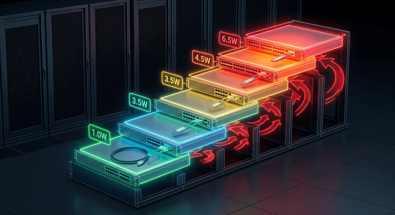
The result is a vertical temperature gradient that can span 10–20°C across a switch stack.
Lower ports might sit at a comfortable 48°C. Upper ports — the ones receiving pre-heated intake air — can hit 64–68°C.
At 70°C, many commercial-grade QSFP28 modules reach their case temperature limit. You may be only a few degrees away from thermal instability.
And here is the kicker.
The cages at the top of the switch are often populated with long-reach modules. LR4. ER4. ZR4. The hotter modules.
The physical layout often makes the hottest modules the most exposed to pre-heated air.
Temperature Gradients in Stacked Switches
I have seen this in practice.
A team in Singapore mounted four 48-port switches in two adjacent racks with poor airflow separation. There was no hot-aisle containment. Cooling came from standard CRAH units.
Bottom switch: average module temperature around 48°C.
Top switch: average module temperature around 64°C.
The top switch started throwing DOM alerts every afternoon when ambient temperature peaked. CRC errors spiked. Links flapped.
They thought they had a bad batch of modules.
They actually had an airflow recirculation problem.
Poor switch orientation and hot-air recirculation can add 10–15°C to upper switch intake temperatures. Sometimes more if the hot aisle is poorly contained. Standard front-to-back switches in a proper hot/cold aisle design may see roughly 5–8°C difference from bottom to top. A bad belly-to-belly layout can double that.
Airflow Patterns and Hotspots
Front-to-back switches in hot/cold aisle containment are clean and predictable. Exhaust goes to the hot aisle. Intake pulls from the cold aisle. Mixing is minimized.
Belly-to-belly layouts without containment are different. Exhaust recirculation creates dead zones. Side-intake switches can be even more challenging because they may pull from areas where hot air pools.
Blanking panels matter more than many teams realize. An empty rack space without a blanking panel becomes a bypass route for hot air. Hot exhaust sneaks around the sides and mixes with cold intake air. Your effective cooling capacity drops.
Cooling Math: Watts to BTU/hr
Data center cooling is measured in tons or BTU/hr. Optics power is measured in watts. Here’s the bridge:
1 watt = 3.412 BTU/hr
A 48-port switch with LR4 draws 666W. That’s 2,272 BTU/hr of heat.
A 42U rack with eight of those switches: 18,176 BTU/hr. Just from the switches. Add servers, storage, and PDUs, and you’re looking at 30,000+ BTU/hr per rack.
A standard CRAH unit might deliver 60,000-120,000 BTU/hr total.
But air distribution is the bottleneck.
The rack in the corner of the row gets less airflow than the one directly in front of the vent. I’ve measured 8°C differences between identical racks in the same row.
| Configuration | Typical Temp Delta | Risk Level | Mitigation |
| Hot/cold aisle, contained | 5-8°C | Low | Standard design |
| Hot/cold aisle, uncontained | 8-12°C | Medium | Add containment curtains |
| Belly-to-belly, contained | 10-15°C | Medium-High | Increase CRAH setpoint or add local fans |
| Belly-to-belly, uncontained | 15-20°C+ | High | Redesign layout or use shorter cables |
The belly-to-belly bake is real. Top switch ports running 68°C while bottom ports sit at 48°C. Intermittent CRC errors that took three days to trace. The fix wasn’t new modules. It was rotating every other switch 180 degrees and adding containment curtains. Problem solved. Temps dropped 12°C.
For rack architecture guidance that includes airflow planning, see our 100G network design guide.
QSFP28 Temperature Classes and Derating
Most QSFP28 modules are commercial-grade. That’s 0°C to +70°C case temperature. But case temperature isn’t ambient temperature. It’s the temperature of the module’s metal housing, which is usually 10-20°C hotter than the air entering the switch.
Commercial vs Extended vs Industrial
| Grade | Case Temp Range | Best For | Typical Price Premium |
| Commercial (C-temp) | 0°C to +70°C | Standard data centers | Baseline |
| Extended (E-temp) | -5°C to +85°C | Broader server environments | 10-20% |
| Industrial (I-temp) | -40°C to +85°C | Outdoor, edge, telecom huts | 25-40% |
Commercial-grade modules cover most data center deployments. The data center air is usually controlled, and module case temperature often sits in the 40–60°C range.
Extended-grade modules are useful when you do not fully control the environment. Server closets with basic HVAC. Edge locations with seasonal swings. Remote sites where cooling is less predictable.
Industrial-grade modules are more specialized but increasingly common. Telecom huts. Outdoor cabinets. 5G small-cell backhaul. Industrial networks. Traffic control systems where summer cabinet temperatures can climb far above a normal data center environment.
What Happens at Temperature Extremes
On the hot side, three things degrade simultaneously:
- Tx optical power may decrease
- Rx sensitivity can degrade
- Laser bias current may increase
- BER can rise before a hard alarm is triggered
- Fan speed and system power may increase as the switch tries to compensate
That last point is the thermal runaway risk. A module running at 68°C draws more power than the same module at 45°C. The difference is usually 5-10%. Small per module. Significant when multiplied across 512 ports.
On the cold side, most QSFP28 modules work fine down to 0°C.
Below that, some variants need care. BiDi modules sometimes have cold-start restrictions. They need to be hot-swapped below +10°C rather than powered on from cold.
A few “lite” commercial modules (Cisco QSFP-100G-SM-SR, for example) are rated only +10°C to +60°C.
Read the fine print.
Reading DDM Temperature Alerts
QSFP28 modules report case temperature through SFF-8636 DOM (Digital Optical Monitoring). Most switch CLIs can read it. Most NMS platforms can graph it.
Here’s the threshold strategy that actually works:
Normal operating range: 45-55°C case temperature
Alert threshold: 55°C (15°C below the 70°C commercial limit)
Critical threshold: 65°C (5°C of headroom before hard shutdown)
Hard limit: 70°C (module may throttle or drop link)
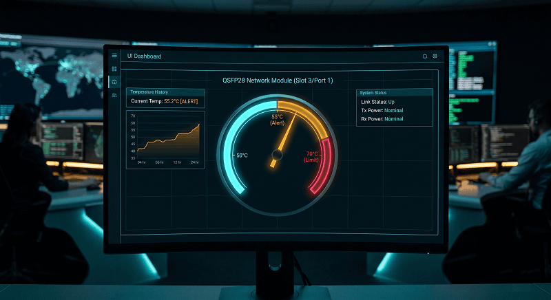
Don’t wait for 70°C.
By the time you hit the hard limit, BER may already have increased. Application latency may already be affected. I have seen 100G links throw CRC errors in the low 60°C range that cleaned up completely after airflow improvements dropped module temperatures by 8–10°C.
The module did not fail. The link did not always drop. It just became unreliable.
Set your monitoring alerts at 55°C for commercial-grade modules. That is early enough to act, but late enough to avoid noise from normal load variation.
QSFP28 vs QSFP+ Power Comparison
If you’re upgrading from 40G to 100G, power is part of the TCO equation. Most people calculate port cost and cabling. Fewer people calculate the power infrastructure upgrade.
Wattage Difference per Port
QSFP+ SR4: 1.5-2.5W
QSFP+ LR4: 2.5-3.5W
QSFP28 SR4: 3.0-3.5W
QSFP28 LR4: 4.0-5.0W
The delta is roughly 1.0-1.5W per port. Doesn’t sound like much. Until you multiply.
Rack-Level Impact of the Upgrade
A 40G deployment with 256 QSFP+ LR4 ports:
256 x 3.0W = 768W optics power
The same deployment at 100G with 256 QSFP28 LR4 ports:
256 x 4.5W = 1,152W optics power
That’s a 384W increase. Just from the modules. Add higher-base-power 100G switches, and the total rack delta can hit 500-600W. You might need to upgrade PDUs or redistribute load across phases.
When Power Savings Offset Upgrade Cost
There’s a counterintuitive angle here. Sometimes the upgrade lowers power.
If your 40G deployment uses LR4 optics everywhere — even for 2-meter inter-rack links — you’re burning 3.0W per port for no reason. Replacing those with QSFP28 passive DACs at 0.5-1.0W drops power by 60-80% on those links.
I’ve seen this in practice. A financial services firm upgraded from 40G to 100G and replaced 60% of their optics with DACs. Total rack power went down 180W despite the faster signaling. They saved money on cooling infrastructure they no longer needed.
| Form Factor | SR4 Power | LR4 Power | Rack Impact (256 ports) |
| QSFP+ (40G) | 1.5-2.5W | 2.5-3.5W | 640-896W |
| QSFP28 (100G) | 3.0-3.5W | 4.0-5.0W | 1,024-1,280W |
| Delta | +0.5-1.5W | +1.0-1.5W | +256-384W |
Planning a migration? Our QSFP28 to 400G migration guide covers TCO analysis including power costs.
5-Step Thermal Planning Checklist
Here’s the framework I use before ordering hardware. It’s not complicated. But it catches the mistakes that cost days.
Step 1: Inventory All Modules by Type and Wattage
List every module type in your deployment. SR4 at 3.5W. LR4 at 4.5W. ER4 at 5.5W. Don’t guess. Use the datasheet max, not the typical. Planning for worst-case keeps you safe.
Step 2: Calculate Total Optics Power per Switch
Multiply ports by module watts.
Optics Power = Ports × Module Watts
48 ports of LR4 at 4.5W = 216W. Write it down per switch.
Step 3: Add Base Switch Power and Apply the 80% PDU Rule
Minimum PDU Rating = (Base Power + Optics Power) ÷ 0.8
(450W + 216W) ÷ 0.8 = 833W minimum per switch. Round up to the next standard PDU size. Don’t forget redundant feeds double your circuit count.
Step 4: Model Belly-to-Belly Temperature Rise
If your switches mount belly-to-belly, add 10-15°C to your upper switch intake temperature. Size your cooling for the hot switch, not the average. If you can’t redesign the layout, budget for higher fan speeds or local rack cooling.
Step 5: Set DDM Alerts 15°C Below Thermal Limit
For commercial-grade modules (0-70°C), set alerts at 55°C. For extended-grade (-5 to +85°C), set alerts at 70°C. Review trends weekly, not just alarms. A steady climb from 48°C to 58°C over a month tells you something’s degrading — maybe filters, maybe CRAH performance, maybe summer arriving.
FAQ
What is the typical power consumption of a QSFP28 module?
QSFP28 modules typically draw 3.0W to 6.5W depending on type. SR4 and BiDi run 3.0-3.5W. LR4 and CWDM4 run 4.0-5.0W. ER4 and ZR4 run 4.5-6.5W. Coherent variants with DSPs can exceed 15W. Passive DACs and AOCs use 0.5-1.5W.
What is the operating temperature range of QSFP28 transceivers?
Most QSFP28 modules are commercial-grade rated for 0°C to +70°C case temperature. Extended-grade modules operate from -5°C to +85°C. Industrial-grade modules handle -40°C to +85°C for outdoor and edge deployments. Always check case temperature, not ambient air temperature.
How much power does a 48-port QSFP28 switch consume?
A fully loaded 48-port switch with LR4 modules typically draws 650-700W total. Base switch power is 450-500W. Optics add 192-240W depending on module type. Size your PDU for 833W minimum using the 80% safety rule.
What is belly-to-belly thermal stacking in data centers?
Belly-to-belly stacking occurs when switches mount facing each other in adjacent racks. Exhaust from the lower switch feeds directly into the upper switch’s intake. Upper ports can run 10-15°C hotter than lower ports, pushing modules near their 70°C thermal limit.
Do QSFP28 modules consume more power than QSFP+?
Yes. QSFP28 modules typically draw 1.0-1.5W more per port than equivalent QSFP+ modules. A 256-port deployment sees roughly 256-384W higher optics power at 100G versus 40G. However, using DAC cables for short links can offset or reverse this increase.
Can I use DDM to monitor QSFP28 temperature?
Yes. QSFP28 modules expose case temperature through SFF-8636 DOM registers. Most switch CLIs and NMS platforms can read and alert on these values. Set alert thresholds at 55°C for commercial-grade modules to catch thermal issues before performance degrades.
Should I use DAC cables to reduce power consumption?
If your link is under 3 meters, absolutely. Passive DACs draw 0.5-1.0W compared to 3.5-5.0W for optical transceivers. That’s a 75-85% power reduction per link. At scale, the savings affect PDU sizing, cooling capacity, and operating cost.
Conclusion
QSFP28 power consumption isn’t a secondary consideration. It’s a primary design input that determines whether your rack stays within thermal envelope or starts throwing alarms.
The key numbers to remember:
SR4: 3.0-3.5W. LR4: 4.0-5.0W. ZR4: 5.5-6.5W. Know your module types.
Optics can equal or exceed base switch power. A 48-port LR4 switch draws 666W total — 216W from modules alone.
Belly-to-belly configs add 10-15°C. Plan for it or redesign your airflow.
Set DDM alerts at 55°C, not 70°C. Performance degrades before the hard limit.
DAC and AOC at 0.5-1.5W can cut rack power by 75% on short links.
If you’re planning a 100G deployment, size your power and cooling for the optics — not just the switch. The math takes five minutes. The outages take days.
Ready to spec your QSFP28 modules? FiberMall offers SR4, LR4, CWDM4, ER4, and ZR4 modules with full DOM support and MSA compliance. Contact our team for thermal planning support and volume pricing.
Related Products:
-
 QSFP28-100G-SR4 100G QSFP28 SR4 850nm 100m MTP/MPO MMF DDM Transceiver Module
$40.00
QSFP28-100G-SR4 100G QSFP28 SR4 850nm 100m MTP/MPO MMF DDM Transceiver Module
$40.00
-
QSFP28-100G-IR4 100G QSFP28 IR4 1310nm (CWDM4) 2km LC SMF DDM Transceiver Module
$110.00
-
QSFP28-100G-DR1 100G QSFP28 Single Lambda DR 1310nm 500m LC SMF with FEC DDM Optical Transceiver
$180.00
-
QSFP28-100G-PSM4 100G QSFP28 PSM4 1310nm 500m MTP/MPO SMF DDM Transceiver Module
$180.00
-
QSFP28-100G-FR1 100G QSFP28 Single Lambda FR 1310nm 2km LC SMF with FEC DDM Optical Transceiver
$215.00
-
Arista Networks QSFP-100G-LRL4 Compatible 100G QSFP28 LRL4 1310nm (LWDM4) 2km LC SMF DDM Transceiver Module
$245.00
-
QSFP28-100G-LR1 100G QSFP28 Single Lambda LR 1310nm 10km LC SMF with FEC DDM Optical Transceiver
$265.00
-
QSFP28-100G-SR1.2 Single Rate 100G QSFP28 BIDI 850nm & 900nm 100m LC MMF DDM Optical Transceiver
$280.00
-
QSFP28-100G-LR4 100G QSFP28 LR4 1310nm (LAN WDM) 10km LC SMF DDM Transceiver Module
$285.00
-
QSFP28-100G-SWDM4 100G QSFP28 SWDM4 850nm-940nm 100m LC MMF DDM Optical Transceiver
$300.00
-
QSFP28-100G-LR4-20 100G QSFP28 LR4 1310nm LWDM4 20km LC SMF DDM Transceiver Module
$300.00
-
QSFP28-100G-BDRX 100G QSFP28 BIDI 850nm & 900nm Only Receiver 100m LC MMF Optical Transceiver
$379.00
-
QSFP28-100G-SRBD Dual Rate 40G/100G QSFP28 BIDI 850nm & 900nm 100m LC MMF DDM Optical Transceiver
$449.00
-
QSFP28-100G-ER1 100G QSFP28 ER1 Single Lambda 1310nm 40km PAM4 LC SMF DDM Transceiver Module
$1250.00