200G isn’t the future. It’s the upgrade happening right now.
Data center operators we’ve worked with are swapping out 100G links faster than most people think. The reason is pretty simple: AI training clusters, hyperscale spine fabrics, and storage networks all need more bandwidth. A lot more. The QSFP56 transceiver is the workhorse making that jump possible without rebuilding your entire fiber plant.
Most guides on this topic do the same thing. They compare QSFP56 against QSFP-DD and call it a day. That’s useful, but only if you already know what QSFP56 actually does. Here’s the problem: if you’re designing a 200G network, you need specifics. Which module type do you actually need? How much power will it draw? Will it work in your switches? What about FEC?
This guide covers all of that.
We’ve debugged enough PAM4 links and thermal issues to know where the real questions are. In this guide, you’ll find every QSFP56 module type explained with actual power numbers, a full compatibility matrix for Cisco, Arista, Juniper and NVIDIA switches, real pricing ranges, and specific guidance for AI cluster deployments. We’ll also walk through a common mistake we see with FEC configuration that can cost you half your link speed.
If you’re upgrading from 100G QSFP28, start here.

What Is QSFP56?
QSFP56 stands for Quad Small Form-Factor Pluggable 56. The name itself tells you the core story: four lanes, each running at about 56 gigabaud. But the number that actually matters is 200. Four lanes × 50 Gbps = 200 Gbps total. That’s the headline.
The Form Factor
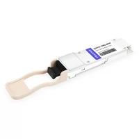
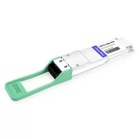
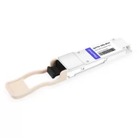
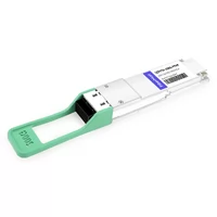
Physically, a QSFP56 module looks identical to QSFP28. Same 38-pin edge connector. Same hot-pluggable dimensions. Same cage size. If you held one in each hand, you couldn’t tell them apart without reading the label.
This matters because you can often reuse cable infrastructure and switch cages when upgrading from 100G to 200G. But don’t get fooled by the looks. The electrical signaling is completely different, which we’ll get to shortly.
PAM4 Signaling Explained
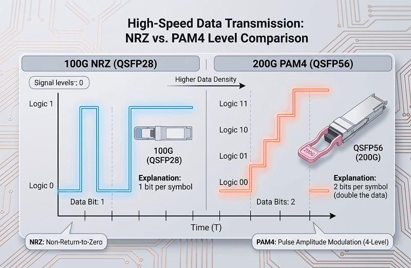
PAM4 is the secret sauce here. Traditional 100G QSFP28 uses NRZ signaling — Non-Return-to-Zero. Think of NRZ like a light switch. It’s either on (1) or off (0). One bit per symbol. Simple, clean, but limited.
PAM4 uses four voltage levels instead of two. Each symbol carries two bits: 00, 01, 10, or 11. You get twice the data per clock cycle without adding more wires. Pretty clever.
There’s a tradeoff, of course. Those four levels are closer together than NRZ’s two levels. The signal-to-noise margin drops by roughly 9 dB. Your fiber needs to be cleaner, your connectors need better mating, and your DSP has to work harder to recover the signal. In practice, this means 200G links are more sensitive to dirty connectors than 100G links. We’ve seen techs chase “bad” transceivers for hours only to find a contaminated LC connector.
4×50G Lane Architecture
Under the hood, QSFP56 runs four electrical lanes at 53.125 Gbps each. The math works out to 212.5 Gbps before encoding overhead, which settles at a clean 200 Gbps usable. The electrical interface spec is 200GAUI-4. Each lane operates at roughly 56 gigabaud — hence the “56” in QSFP56.
Key Standards
QSFP56 didn’t appear out of nowhere. It sits on solid standards:
IEEE 802.3bs — defines 200G and 400G Ethernet
IEEE 802.3cd — refines 200G Ethernet specifically
QSFP56 MSA — the multi-source agreement covering mechanical dimensions, pinouts, and management (SFF-8665, SFF-8024, SFF-8679)
These standards are why a QSFP56 from FiberMall will work in a switch from Cisco or Arista. MSA compliance is the whole point. For a deeper comparison of how QSFP56 fits alongside older form factors, see our QSFP28 vs QSFP+ vs QSFP56 guide.
QSFP56 Module Types Explained
Here’s where most guides get thin. They list the module types and move on. But you need to know when to pick each one. The wrong choice costs you money, power, or link stability.
200GBASE-SR4 (Multimode, 100m)
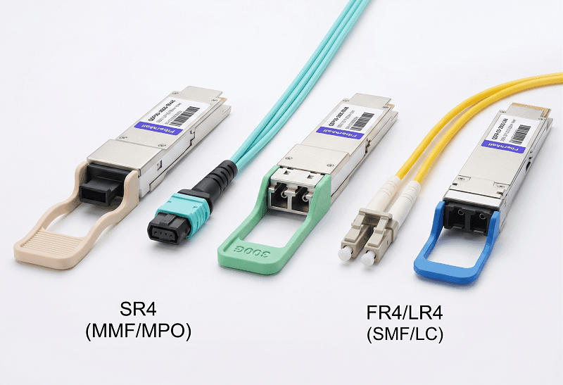
SR4 is the multimode workhorse. It uses an 850nm VCSEL array and pairs with an MPO-12 connector. On OM4 fiber, you get 100 meters. On OM5, that stretches to 150 meters.
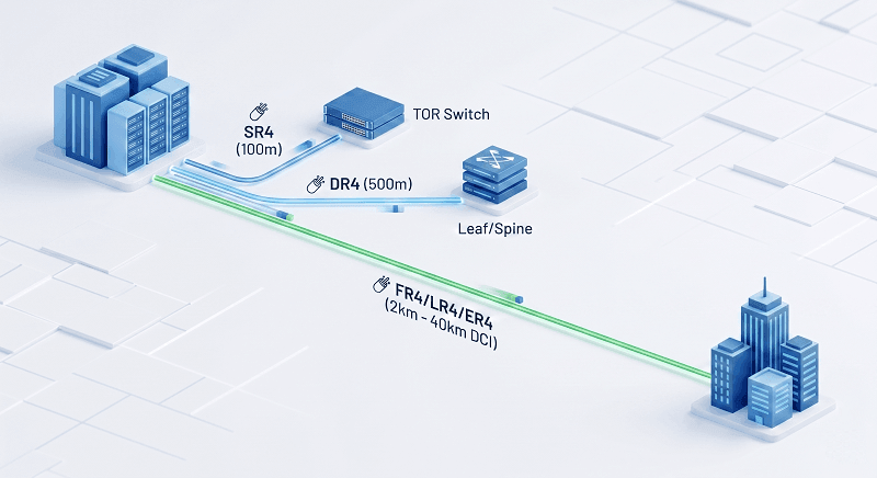
Power draw is typically 3.3 to 5 watts. That’s the lowest of any QSFP56 module type. SR4 is your go-to for intra-data center links: rack-to-rack within the same room, top-of-rack to spine switches, and AI cluster GPU interconnects where the servers sit close together. If your link fits inside a single row, SR4 is usually the right call.
200GBASE-DR4 (Single-Mode Parallel, 500m)
DR4 switches to single-mode fiber but keeps the parallel architecture. Four 1310nm lasers, still MPO-12 connector, 500 meter reach. Power runs 4 to 5 watts.
DR4 sits in a useful middle ground. Your data center might be transitioning from multimode to single-mode. Or your spine links need to reach across the room but not leave the building. DR4 handles both. It’s also the natural upgrade path if you’ve already deployed 100GBASE-DR1 or DR4 and want to keep the same fiber type.
200GBASE-FR4 (CWDM4, 2km)
FR4 uses CWDM4 wavelength multiplexing: 1271, 1291, 1311, and 1331 nanometers. All four wavelengths travel down a single duplex LC fiber pair. Reach is 2 kilometers.
Power jumps here. FR4 typically draws 5 to 7 watts, the highest of the QSFP56 family. Those EML (Electroabsorption Modulated Laser) sources are precise but power-hungry.
Use FR4 for campus links, building-to-building connections, 5G midhaul, and short DCI runs. Anytime you need to leave the data center but aren’t crossing a metro area, FR4 is your module.
200GBASE-LR4 (LWDM4, 10km)
LR4 switches to LWDM4 wavelengths: 1295, 1300, 1304, and 1309 nanometers. Same duplex LC connector, but the tighter wavelength spacing and higher-quality optics push reach to 10 kilometers standard. With FEC enabled, some implementations stretch to 20 km.
Power is around 5 watts — actually a bit lower than FR4 in many cases because the laser design is more mature. LR4 is built for metro DCI, longer campus backbones, and telecom aggregation links.
200GBASE-ER4 (Extended Reach, 40km)
ER4 extends to 40 kilometers on duplex LC single-mode fiber. It uses 1310nm-based optics with amplification. Power draw lands at 5.5 to 7 watts.
This is your regional link module. ER4 connects data centers across a city or connects remote POPs. It’s not a data center module per se — it’s a telecom and DCI module. Most engineers won’t spec ER4 unless they know the exact fiber distance and loss budget.
| Module Type | Fiber | Connector | Distance | Power | Best For |
| 200GBASE-SR4 | OM4/OM5 MMF | MPO-12 | 100m (OM4) / 150m (OM5) | 3.3-5W | Intra-DC, AI clusters |
| 200GBASE-DR4 | SMF | MPO-12 | 500m | 4-5W | Spine-leaf, row-to-row |
| 200GBASE-FR4 | SMF | Duplex LC | 2km | 5-7W | Campus, DCI, 5G |
| 200GBASE-LR4 | SMF | Duplex LC | 10km (20km w/ FEC) | ~5W | Metro DCI, telecom |
| 200GBASE-ER4 | SMF | Duplex LC | 40km | 5.5-7W | Regional networks |
The FR4 is the power hog. But for 2km links, it’s usually your only choice. For a deeper dive into selecting the right module, see our QSFP56 module types guide.
QSFP56 Power Consumption & Thermal Design
Most guides skip power entirely. That’s a mistake. At 200G, optics can consume more energy than the switch ASIC itself. Plan for it.
Per-Module Wattage by Type
SR4 is the efficiency winner at 3.3 to 5 watts. DR4 adds a bit more at 4 to 5 watts. FR4 and ER4 both run 5.5 to 7 watts. LR4 sits around 5 watts.
These numbers look small until you multiply by port count.
| Module | Typical Power | Max Power | Heat (BTU/hr) | Best For |
| SR4 | 3.3W | 5W | 11-17 | Dense intra-rack |
| DR4 | 4W | 5W | 14-17 | Spine-leaf |
| FR4 | 5.5W | 7W | 19-24 | Longer reach |
| LR4 | 4.5W | 5.5W | 15-19 | Metro links |
| ER4 | 5.5W | 7W | 19-24 | Regional |
PAM4 DSP Power Penalty
PAM4 needs a DSP — Digital Signal Processor — to encode and decode those four voltage levels. That DSP adds roughly 1 to 2 watts compared to an equivalent NRZ module. Sounds bad, right?
Actually, QSFP56 often wins on power. Here’s why: QSFP-DD at 200G uses eight lanes of 25G NRZ. Eight lasers, eight receivers, more complexity. QSFP56 uses four lanes of 50G PAM4. Fewer optical components. In practice, a QSFP56 200G module usually draws less power than a QSFP-DD 200G module running the same distance. The DSP penalty is real, but the lane reduction more than pays for it.
Rack-Level Thermal Impact
Let’s run the math. A 32-port switch fully loaded with FR4 modules pulls 160 to 224 watts just from optics. The same port count at 100G with QSFP28 runs about 112 to 144 watts. You’re adding roughly 50% more heat for 2× the bandwidth. That’s actually a pretty good trade. But your cooling needs to handle it.
We’ve seen thermal throttling in poorly ventilated IDF closets where 200G switches were installed. The switches didn’t fail, but they logged temperature warnings every afternoon. Moving to SR4 modules and adding a single exhaust fan fixed it.
Temperature Classes
QSFP56 modules come in three temperature grades:
Commercial: 0°C to +70°C — standard data center
Extended: -5°C to +85°C — edge and 5G environments
Industrial: -40°C to +85°C — outdoor telecom, harsh environments
Most data center deployments use commercial grade. But if you’re deploying in an uncontrolled environment, check the temperature rating before you order. The part numbers often look identical.
For detailed thermal planning guidance, see our QSFP56 power and thermal guide.
QSFP56 vs QSFP-DD: The 200G Decision
This is the question everyone asks. And most articles get the framing wrong. They compare at 400G. But if you’re deciding at 200G, the math changes.
When QSFP56 Wins
Cost-sensitive 200G deployments are the obvious case. QSFP56 modules cost less than QSFP-DD modules at the same speed. The supply chain is mature, and competition among vendors is fierce.
Power is another win. For dedicated 200G links, QSFP56 typically draws 4 to 7 watts. QSFP-DD at 200G uses eight lanes at 25G NRZ, which usually lands at 3.5 to 5 watts. Wait — that’s lower? Sometimes yes, sometimes no. The real win is simpler thermal design. Four lanes generate less distributed heat than eight lanes. Your switch heatsinks can handle it more easily.
Fiber plant compatibility matters too. If you’ve already deployed QSFP28, your fiber and cable infrastructure probably handles QSFP56 without changes. Same MPO-12 for parallel, same duplex LC for WDM.
When QSFP-DD Wins
Future-proofing is the big one. QSFP-DD has a native 400G path. Upgrade the module, keep the switch. With QSFP56, there’s no 400G module. You’d replace the switch entirely.
Port density is another factor. A 1RU switch can fit about 36 QSFP56 ports. That same 1RU can hold roughly 64 QSFP-DD ports. Hyperscale operators with constrained rack space care about that difference a lot.
Latency-sensitive HPC workloads sometimes prefer QSFP-DD at 200G because the 8×25G NRZ path avoids PAM4 DSP latency. We’re talking about 100 to 200 nanoseconds difference. For most workloads, that doesn’t matter. For some HPC codes, it does.
Power Comparison
| Parameter | QSFP56 (200G) | QSFP-DD (200G) | QSFP-DD (400G) |
| Power per module | 4-7W | 3.5-5W | 8-14W |
| Lane config | 4×50G PAM4 | 8×25G NRZ | 8×50G PAM4 |
| DSP latency | ~100-200ns | Near zero | ~100-200ns |
| Port density (1RU) | ~36 | ~64 | ~64 |
Port Density
Thirty-six ports per 1RU at 200G is plenty for most enterprise and mid-size data centers. Sixty-four ports only matters when you’re building hyperscale fabrics where every rack unit counts. Be honest about your scale before you pay the QSFP-DD premium.
400G Migration Path
QSFP56 is a dead end at 400G. That’s not an insult — it’s a design choice. You buy QSFP56 when you need 200G now and you’re okay replacing switches later. QSFP-DD is an investment in a form factor that scales to 400G and beyond.
Sometimes the older form factor wins. If your 200G deployment has a 3-year life and you’re not going to 400G in that window, QSFP56 saves you money without sacrificing performance. If you’re thinking about migration, read our QSFP28 to 400G migration guide and QSFP56 to 400G path guide.
QSFP56 for AI/ML Clusters & HPC
AI is the reason 200G exists. Seriously. Without the explosion of GPU training clusters, 200G would be a niche transition speed that most networks skipped. The demand is real.

InfiniBand HDR & 200G Ethernet
InfiniBand HDR runs at 200 Gbps. That’s not a coincidence — it’s the standard. And QSFP56 is the physical layer module that HDR uses. NVIDIA’s DGX systems, HGX baseboards, and most major GPU server platforms ship with QSFP56 ports for GPU-to-GPU and GPU-to-switch connectivity.
200G Ethernet is the alternative. Same QSFP56 physical layer, different protocol stack. Most AI clusters we see use InfiniBand for the GPU fabric and Ethernet for the management and storage network. Both run over QSFP56.
GPU Interconnect Topologies
AI clusters need all-to-all communication between GPUs. Not just some-to-some. Every GPU needs to talk to every other GPU with minimal bottleneck. Two topologies dominate:
Fat-tree is the classic approach. A spine layer of 200G switches connects to leaf switches, which connect to GPU servers. QSFP56 SR4 handles the leaf-to-spine links inside the rack. FR4 or DR4 handles spine-to-spine if the cluster spans multiple rows.
Rail-optimized topology groups GPUs by their physical location in the server rack. GPUs in the same “rail” connect directly at 200G, reducing hop count. This is getting popular in large training clusters because it cuts down on switch buffer contention.
Latency Considerations
PAM4 DSP adds about 100 to 200 nanoseconds of latency per hop. For AI training workloads, that’s basically zero compared to computation time. A single GPU training step might take milliseconds. A few hundred nanoseconds of network latency doesn’t register.
For HPC workloads — weather simulation, molecular dynamics, finite element analysis — latency matters more. Some HPC engineers prefer QSFP-DD at 200G specifically to avoid that DSP penalty. It’s a niche concern, but it exists.
RDMA over 200G
RDMA is how AI clusters move data without involving the CPU. Both RoCEv2 and InfiniBand support RDMA. QSFP56 provides the physical layer for both.
The transceiver choice matters less than the network design. A poorly designed fat-tree with great QSFP56 modules will still bottleneck. A well-designed rail-optimized topology with basic SR4 modules will usually outperform it. Focus on topology first, transceiver second. For more on AI-specific deployments, see our QSFP56 for AI clusters guide.
QSFP56 Compatibility & Backward Compatibility
This section is where deployments go sideways. The physical fit means nothing if the electrical handshake fails.
Switch Compatibility (Cisco, Arista, Juniper, NVIDIA)
Not every switch with a QSFP cage supports QSFP56. The switch ASIC must handle 50G PAM4 electrical signaling. Here’s what actually works:
| Switch Vendor | Platform | QSFP56 Support | Notes |
| Cisco | Nexus 9000 (select line cards) | Yes | Verify specific line card model |
| Arista | 7060X4, 7170 series | Yes | Full 200G support |
| Juniper | QFX5200, QFX5220 | Yes | Check JunOS version |
| NVIDIA | Spectrum-3 and newer | Yes | Includes SN4000 series |
| Dell | Z9264F-ON, Z9332F-ON | Yes | OS10 support required |
Always check the compatibility matrix. We’ve seen people buy QSFP56 modules for switches that only support QSFP28. The module fits in the cage. It just won’t link.
QSFP28 Port Fallback
Here’s a common misconception: QSFP56 fits in a QSFP28 port physically. Same dimensions, same cage. But it’s NOT electrically compatible.
Plug a QSFP56 into a QSFP28 port and one of three things happens. The link doesn’t come up at all. It trains at 40G. Or it trains at 100G if the module has a fallback mode. You won’t get 200G. The 50G PAM4 signaling is completely different from 25G NRZ.
Don’t assume backward compatibility. Check the switch datasheet.
QSFP-DD Forward Compatibility
QSFP-DD ports can accept QSFP56 modules. Usually through an adapter, sometimes natively. This is actually a decent migration path: deploy QSFP56 now on QSFP-DD switches, then upgrade to 400G QSFP-DD modules later without replacing the switch.
FEC Requirements
RS-FEC (544,514) is mandatory for QSFP56. Both ends must match. This is not optional.
We worked with a team that deployed QSFP56 FR4 between two data centers. One switch had RS-FEC enabled. The other didn’t. The links trained at 100G fallback instead of 200G. They spent two days troubleshooting “bad” fiber before someone checked the FEC configuration. Enable RS-FEC on both sides. Always.
MPO Polarity (SR4/DR4)
MPO cables have polarity types. Type B is mandatory for SR4 and DR4. Type A causes Tx-to-Tx failures — you’re literally transmitting into another transmitter.
Test your cables before deployment. A $50 polarity tester saves hours of debugging. We’ve seen techs replace three sets of transceivers before realizing the cable was Type A. Pretty embarrassing. For the full compatibility picture, see our QSFP56 compatibility matrix.
QSFP56 Cabling Options
Transceivers are only half the story. Your cable choice affects cost, power, latency, and cable management.
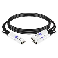
Passive DAC (≤5m)
Passive Direct Attach Copper cables connect QSFP56 to QSFP56 without any optics. Just copper. Power draw is under 0.5 watts per end. Cost is the lowest of any 200G interconnect. Latency is essentially zero — no optical conversion, no DSP.
Use DAC for rack-to-rack links where the switches are close. Same row, adjacent racks, maybe 3 to 5 meters. They’re thick and stiff, so cable management gets annoying if you have dozens of them. But for short links, nothing beats the cost.
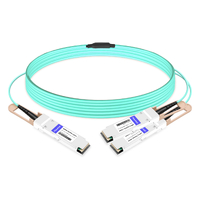
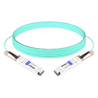
Active Optical Cable (≤100m)
AOC replaces the copper with fiber. The transceivers are permanently attached to the cable — you can’t separate them. Power is under 1 watt per end. The cable is lighter and more flexible than DAC.
AOC works for row-to-row connections inside a data center. Up to 100 meters. You lose the ability to swap cable types or clean connectors, but you gain density and airflow. Most hyperscale operators use AOC extensively for intra-cluster GPU links.
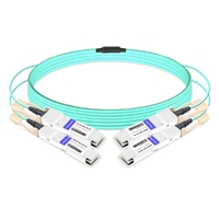
Breakout Cables (200G to 4×50G)
Breakout cables split one QSFP56 into four SFP56 connections. This is how you connect a 200G switch port down to 50G servers.
DAC breakout cables are available. AOC breakout cables too. Just verify that your switch supports breakout mode. Not all switches do, and the ones that do often need specific port groupings.
Breakout cables are where the real savings happen. One 200G switch port with a breakout cable replaces four separate 50G switch ports.
Fiber Selection (OM4/OM5 vs SMF)
For SR4, OM4 gets you 100 meters. OM5 stretches to 150 meters. If you’re building new, OM5 costs about 20% more but gives you headroom.
For DR4, FR4, LR4, and ER4, single-mode fiber is required. No exceptions. And at 200G with PAM4, fiber cleanliness matters more than at 100G. That 9 dB SNR penalty we mentioned earlier? Contaminated connectors eat into it fast. Clean to IEC 61300-3-35 standard.
| Cable Type | Reach | Power | Cost | Best For |
| Passive DAC | ≤5m | <0.5W | Lowest | Rack-to-rack |
| AOC | ≤100m | <1W | Low | Intra-DC |
| Breakout DAC | ≤5m | <0.5W | Low | Server connectivity |
| Breakout AOC | ≤100m | <1W | Medium | Server row |
For a detailed cable comparison, see our QSFP56 DAC vs AOC guide.
QSFP56 Pricing & Cost Per Bit
Let’s talk numbers. These are street prices for third-party MSA-compliant modules in mid-2026. OEM prices from Cisco or Juniper are 3× to 5× higher.
Module Price Ranges by Type
| Module | Price Range (3rd-party) | Cost/Gbps | Volume (1K+) |
| SR4 | $200-400 | $1.00-2.00 | $140-280 |
| DR4 | $300-500 | $1.50-2.50 | $210-350 |
| FR4 | $400-700 | $2.00-3.50 | $280-490 |
| LR4 | $500-900 | $2.50-4.50 | $350-630 |
| ER4 | $800-1,200 | $4.00-6.00 | $560-840 |
SR4 is cheap because VCSEL arrays are mature and high-volume. ER4 is expensive because it needs amplification and precision optics.
Cost Per Gigabit vs QSFP28 and QSFP-DD
The cost per bit keeps dropping. QSFP28 LR4 runs about 15 to 20 per Gbps. QSFP56 FR4 drops to 2 to 3.50 per Gbps. QSFP-DD 400G FR4 gets down to 1.50 to 2.50 per Gbps.
This trend is why data centers upgrade speed generations even when they don’t strictly need the bandwidth. The cost per bit improves enough to justify the switch replacement.
Volume Pricing
Order 100+ units and you typically see 20% to 30% off list. At 1,000+ units, discounts hit 35% to 45%. OEM-branded modules from switch vendors don’t offer this flexibility. Third-party MSA modules do.
FiberMall’s pricing follows these ranges. Contact us for specific quotes on SR4, DR4, FR4, LR4, and ER4 modules. For detailed pricing analysis, see our QSFP56 price guide.
200G Network Design with QSFP56
Speed is only useful if your architecture can use it.
Spine-Leaf at 200G
A typical two-tier spine-leaf fabric uses 200G for the spine layer and 100G for the leaf layer. That’s a 2:1 oversubscription ratio. Every leaf switch has half the uplink bandwidth it needs for full non-blocking.
Full 200G leaf means matching 200G leaf switches with 200G server NICs. Most environments don’t need that. AI training clusters do. Storage networks sometimes do. General compute usually doesn’t.
For spine-leaf links inside the data center, SR4 handles rack-to-rack. FR4 handles spine-to-spine if your data center has multiple rooms.
Top-of-Rack Oversubscription
Oversubscription isn’t evil. It’s normal. A typical leaf switch has 48×25G downlinks (1,200 Gbps total) and 8×200G uplinks (1,600 Gbps total). That’s actually 1.33:1 — technically oversubscribed, but barely.
Compare that to 100G uplinks: 48×25G downlinks with 8×100G uplinks gives you 2.5:1 oversubscription. Moving to 200G uplinks cuts that nearly in half. For East-West traffic between servers — which is most of your data center traffic — that matters.
DCI Design
For data center interconnect, match the module to the distance:
Campus DCI (same metro, different buildings): FR4 at 2km
Metro DCI (across town): LR4 at 10km
Regional (city to city): ER4 at 40km
Check your actual fiber distance and loss budget. Don’t spec ER4 for a 5km link just to be safe. You’ll pay twice as much and draw more power than you need. For architecture guidance, see our 200G network design guide.
Frequently Asked Questions
What is a QSFP56 transceiver?
A QSFP56 transceiver is a hot-pluggable optical module that delivers 200 Gigabit Ethernet over four 50G PAM4 lanes. It uses the same physical form factor as QSFP28 but with completely different electrical signaling.
What is the difference between QSFP56 and QSFP28?
QSFP28 delivers 100G using four 25G NRZ lanes. QSFP56 delivers 200G using four 50G PAM4 lanes. Physically they look identical, but QSFP56 is not electrically backward compatible with QSFP28 ports.
Is QSFP56 backward compatible with QSFP28?
Physically, yes — it fits in the same cage. Electrically, no. A QSFP56 module in a QSFP28 port typically won’t link at 200G. It may fall back to 40G or fail to link entirely. Always verify switch compatibility.
What is PAM4 signaling in QSFP56?
PAM4 uses four voltage levels to encode two bits per symbol, doubling throughput without adding lanes. NRZ uses two levels for one bit per symbol. PAM4 is what lets QSFP56 reach 200G with only four lanes.
How much power does a QSFP56 module consume?
Between 3.3 watts (SR4) and 7 watts (FR4/ER4). The average across all types is about 4.5 to 5 watts. Multiply by port count for total switch power consumption.
What is the maximum distance of QSFP56 SR4?
100 meters on OM4 multimode fiber. 150 meters on OM5 multimode fiber. Both use MPO-12 connectors. For longer distances, switch to DR4 (500m), FR4 (2km), LR4 (10km), or ER4 (40km).
Is FEC required for QSFP56?
Yes. RS-FEC (544,514) is mandatory for 200G links. Both ends must have matching FEC configuration. A mismatch usually causes the link to fall back to 100G or fail entirely.
Can I use QSFP56 in a QSFP-DD port?
Usually yes. QSFP-DD ports accept QSFP56 modules either natively or with a simple adapter. This is a useful migration path if you want to deploy 200G now and upgrade to 400G later on the same switch platform.
What is QSFP56 used for in AI clusters?
QSFP56 is the physical layer for InfiniBand HDR and 200G Ethernet. NVIDIA DGX systems and most GPU clusters use QSFP56 for GPU interconnects at 200 Gbps. SR4 handles intra-rack links; FR4 handles longer connections.
How much does a QSFP56 module cost?
Third-party MSA-compliant modules range from 200(SR4) to 1,200 (ER4). Volume discounts start at 100 units. OEM-branded modules from switch vendors cost 3× to 5× more for the same hardware.
Conclusion
QSFP56 is the practical path to 200G. Four lanes of 50G PAM4. Module types from SR4 at 100 meters to ER4 at 40 kilometers. Power ranging from 3.3 watts to 7 watts. Not backward compatible with QSFP28 electrically, but physically identical. FEC is mandatory. And AI clusters are driving more demand than any other application.
The QSFP56 versus QSFP-DD decision comes down to timeline and scale. Need 200G now at the lowest cost? QSFP56 wins. Need 400G in the same switch within two years? QSFP-DD is the smarter investment.
We’ve covered module selection, power planning, switch compatibility, cabling, pricing, and network design. The next step is matching these specs to your actual deployment.
FiberMall supplies QSFP56 SR4, DR4, FR4, LR4, and ER4 modules with full MSA compliance and switch compatibility testing. If you’re planning a 200G deployment, contact our engineering team for a compatibility check and volume quote.
Related Products:
-
 QSFP56-200G-SR4M 200G QSFP56 SR4 PAM4 850nm 100m MTP/MPO APC OM3 FEC Optical Transceiver Module
$139.00
QSFP56-200G-SR4M 200G QSFP56 SR4 PAM4 850nm 100m MTP/MPO APC OM3 FEC Optical Transceiver Module
$139.00
-
QSFP56-200G-FR4S 200G QSFP56 FR4 PAM4 CWDM4 2km LC SMF FEC Optical Transceiver Module
$650.00
-
NVIDIA(Mellanox) MMA1T00-HS Compatible 200G Infiniband HDR QSFP56 SR4 850nm 100m MPO-12 APC OM3/OM4 FEC PAM4 Optical Transceiver Module
$139.00
-
NVIDIA(Mellanox) MMS1W50-HM Compatible 200G InfiniBand HDR QSFP56 FR4 PAM4 CWDM4 2km LC SMF FEC Optical Transceiver Module
$650.00
-
NVIDIA MFS1S90-H003E Compatible 3m (10ft) 2x200G QSFP56 to 2x200G QSFP56 PAM4 Breakout Active Optical Cable
$800.00
-
NVIDIA(Mellanox) MCP7H50-H001R30 Compatible 1m (3ft) Infiniband HDR 200G QSFP56 to 2x100G QSFP56 PAM4 Passive Breakout Direct Attach Copper Cable
$55.00
-
NVIDIA(Mellanox) MFS1S50-H003E Compatible 3m (10ft) 200G HDR QSFP56 to 2x100G QSFP56 PAM4 Breakout Active Optical Cable
$480.00
-
NVIDIA(Mellanox) MFS1S00-H003E Compatible 3m (10ft) 200G HDR QSFP56 to QSFP56 Active Optical Cable
$350.00