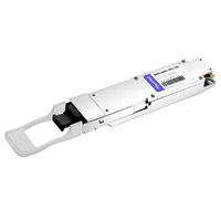
At 2:47 a.m., the NOC dashboard at a Midwest AI lab turned red. Their 200G QSFP56 spine links were pinned at 94% utilization. A distributed training job with 512 GPUs had saturated every east-west path. The ops lead had two choices: throttle the model training or find a way to double bandwidth before the next batch started.
If you’ve deployed QSFP56 for 200G connectivity, you’ve probably already felt this pressure. 200G was the right bridge between 100G QSFP28 and the hyperscale future. But AI clusters, cloud workloads, and video infrastructure are eating through that bridge faster than most teams expected. The question isn’t whether you’ll move to 400G. It’s whether you’ll do it without a fire drill.
This guide walks through a complete QSFP56 to 400G migration playbook. We’ll compare the form factors that matter, map out three migration paths, run rack-level power numbers, and give you a checklist that keeps the cutover boring—which is exactly how network upgrades should be.

Why the Push from QSFP56 to 400G Is Accelerating
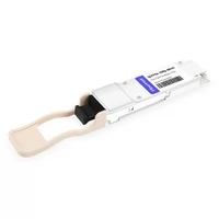
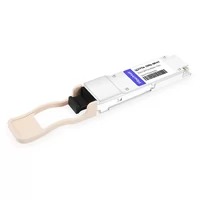
QSFP56 gave data centers a clean 200G step up from QSFP28. Same mechanical footprint. Same 4-lane structure. But instead of 25G NRZ signaling, it uses 50G PAM4. That doubled throughput without doubling port count.
The catch? Workload demand didn’t stop at 200G.
AI training clusters now move terabytes of gradients between GPUs every second. A single 400G link can carry what four 100G links used to handle. Hyperscale operators figured this out early. By 2025, 400G had reached cost parity with 100G on a per-gigabit basis. Today, if you’re building new spine infrastructure, 400G is the baseline.
The real driver isn’t just speed. It’s consolidation. A 32-port 400G switch replaces 128 ports of 100G. Fewer switches. Less fiber chaos. Lower switch power per gigabit. For teams already on QSFP56, the jump to 400G is the next logical step; but only if the migration is planned.
QSFP56 vs. QSFP-DD vs. QSFP112: Picking Your 400G Form Factor
Before you order optics, you need to decide which 400G form factor fits your environment. This choice affects everything: switch selection, power, cooling, backward compatibility, and future upgrades.
Form Factor Comparison
| Form Factor | Speed | Lanes | Modulation | Backward Compatibility | Typical Power |
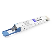
| QSFP56 | 200G | 4×50G | PAM4 | QSFP28, QSFP+ | 4-7W |
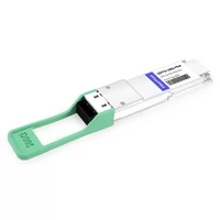
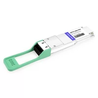
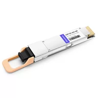
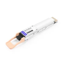
| QSFP-DD (QSFP56-DD) | 400G | 8×50G | PAM4 | QSFP56, QSFP28, QSFP+ | 10-15W |
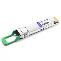
| QSFP112 | 400G | 4×100G | PAM4 | QSFP56, QSFP28, QSFP+ | 10-15W |
| OSFP | 400G/800G | 8×50G or 8×100G | PAM4 | None (native only) | 15-20W+ |
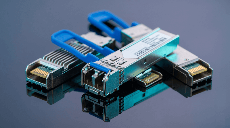
QSFP-DD is the safest bet for most brownfield migrations. Its ports accept QSFP56 modules and run them at 200G. That means you can install 400G switches now, migrate hosts later, and avoid a forklift upgrade.
QSFP112 is newer and more compact. It delivers 400G over 4 lanes of 100G PAM4. The backward compatibility is attractive, but host ASIC support is still maturing. Choose it only if your switches explicitly list QSFP112 support.
OSFP handles more power and is the preferred path for 800G and beyond. But it won’t accept your existing QSFP56 modules. Use OSFP for greenfield AI clusters where thermal headroom matters more than reuse.
The Compatibility Rule That Saves Money
Here’s the detail most migration guides bury: QSFP-DD ports accept QSFP56 modules in 200G mode. The reverse is not true. A QSFP-DD module will not fit into a QSFP56-only cage.
This matters because it lets you deploy 400G-capable spine switches today while leaves stay on 200G. You don’t need to rip and replace everything in one weekend. The existing QSFP56 optics keep working until you’re ready to swap the leaf switches and upgrade endpoints.
Three Migration Paths from QSFP56 to 400G
Every migration falls into one of three patterns. The right one depends on budget, timeline, and whether you’re replacing hardware or extending it.
Path A: Phased Breakout Migration (Most Common)
Install 400G QSFP-DD spine switches. Use breakout cables to connect 200G QSFP56 leaves or 100G QSFP28 endpoints. As each leaf reaches end-of-life, replace it with a 400G-capable model and remove the breakout.
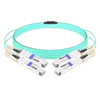
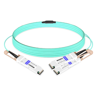
400G QSFP-DD → 2×200G QSFP56: Connects upgraded spines to existing 200G leaves.
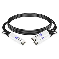
400G QSFP-DD → 4×100G QSFP28: Connects to older 100G server-facing ports.
This path protects CAPEX. You spread the upgrade over 12-24 months. The downside is cable sprawl during the transition and the operational complexity of mixed speeds.

Path B: End-to-End 400G Upgrade
Replace spine and leaf switches in one coordinated rollout. Run native 400G optics everywhere. This is the cleanest architecture and the best fit for new AI/HPC builds where every GPU needs maximum bandwidth.
The upfront cost is higher. The operational simplicity usually pays it back within 18 months.
Path C: Skip 400G and Go to 800G
For some hyperscale and AI deployments, 400G is already a stepping stone. If you’re doing a greenfield build in 2026 and the ASICs support it, 800G OSFP or QSFP-DD800 may be the better long-term bet. This only makes sense if your workloads can saturate 400G today.
Decision Matrix
| Scenario | Recommended Path |
| Existing QSFP56, budget spread over 2 years | Path A: Breakout migration |
| New AI/HPC cluster, maximum bandwidth needed | Path B: End-to-end 400G |
| Greenfield 2026 build, 800G-ready ASICs | Path C: Skip to 800G |
| Mixed 100G/200G/400G environment | Path A with hybrid breakout cables |
Switch ASIC and Platform Compatibility
Not every switch with a QSFP cage can run QSFP56. Not every 400G switch can run QSFP56 modules at 200G. Before you buy anything, verify the ASIC and firmware.
Vendor Platform Support
| Vendor | Platforms with QSFP56/400G Support | Notes |
| Cisco | Nexus 9000 (select line cards), Cisco 8000 | Verify specific model and NOS version |
| Arista | 7060X4, 7170, 7800R4 series | Strong 400G/800G roadmap |
| Juniper | QFX5200, QFX5220, PTX10004 | Check JunOS release notes |
| NVIDIA/Mellanox | Spectrum-3, SN4000, ConnectX-7 | Includes InfiniBand HDR 200G |
| Dell | Z9264F-ON, Z9332F-ON | OS10 support required |
What to Verify Before Ordering
1. ASIC lane support: The switch must support 50G PAM4 electrical lanes for QSFP56 and 400G operation.
2. Breakout mode: Confirm the switch supports the breakout configuration you plan to use (4×100G or 2×200G).
3. Firmware version: Some features only work on recent releases. Check vendor release notes.
4. Power budget: 400G modules pull 10-15W each. Make sure line cards and chassis can supply that across all ports.
If you’re unsure, run a small qualification test with one line card and a few modules before placing a large order.
Fiber Infrastructure and Cabling Strategy
The good news: 400G doesn’t automatically require new fiber. The bad news: 400G is far less forgiving of sloppy fiber practices than 100G was.
Fiber Types by Reach
| 400G Module | Fiber Type | Typical Reach |
| 400G SR8 | OM4/OM5 multimode | Up to 100m |
| 400G DR4 | OS2 single-mode | 500m |
| 400G FR4 | OS2 single-mode | 2km |
| 400G LR4 | OS2 single-mode | 10km |
| 400G ZR/ZR+ | OS2 single-mode | 80-480km |
For most data center inter-switch links, OS2 single-mode is the safer long-term choice. It supports every reach class and removes the distance anxiety that comes with multimode.
Connector and Polarity Discipline
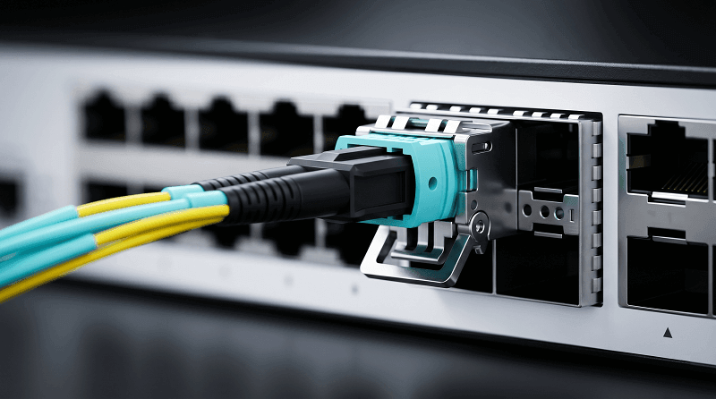
400G parallel optics typically use MPO-12 (for DR4) or MPO-16 (for SR8) connectors. A polarity mismatch that might have caused intermittent errors at 100G can kill a 400G link entirely. During migration:
Audit every trunk with OTDR before cutover.
Verify MPO polarity (Method A, B, or C) and document it per link.
Confirm APC vs. UPC connector types match the module spec.
Clean every connector before insertion.
One New York financial firm learned this the hard way. They migrated their trading fabric to 400G over a weekend. Eight links refused to train. After six hours of troubleshooting, the team found that half the MPO trunks had reversed polarity at a single patch panel. The fix took 20 minutes. The outage cost far more.
Power, Cooling, and Rack Density Planning
This is where 400G migrations quietly fail. Teams budget for switch capital cost and optics, but they underestimate the power and thermal impact.
Per-Module Power Consumption
| Form Factor | Typical Power | Max Power |
| QSFP28 (100G) | 3.5-4.5W | ~5W |
| QSFP56 (200G) | 4-7W | ~8W |
| QSFP-DD (400G) | 10-14W | ~15W |
| OSFP (400G/800G) | 15-20W | 25W+ |
The per-module increase is significant. But the power per Gbps actually improves. A 400G module at 14W delivers 0.035W/Gbps. A 100G module at 4.5W delivers 0.045W/Gbps. Over the whole network, you’re more efficient.
Rack-Level Calculation Example
Consider a 32-port 400G switch fully populated with 14W modules:
Optics power: 32 × 14W = 448W
Switch ASIC and fabric: ~400W
Total per switch: ~850W
A 42U rack with eight of these switches draws roughly 6.8kW just for networking. Add servers, storage, and cooling overhead, and you can easily exceed 14kW per rack. If your data center was designed for 100G-era power densities, you’ll need to rebalance load or add cooling before full migration.
Practical tip: Plan for worst-case power, not typical. Summer afternoons and cooling maintenance windows are when thermal issues show up.
Step-by-Step Migration Checklist
A 400G migration should be boring. Boring means no surprises. Use this checklist to keep it that way.
Phase 1: Assessment (Weeks 1-4)
Inventory all switches, line cards, ASICs, and firmware versions.
Document current QSFP56 and QSFP28 module types and quantities.
Run OTDR tests on all fiber trunks. Record insertion loss.
Verify MPO polarity and connector types.
Calculate per-rack power and thermal headroom.
Identify which links are candidates for breakout vs. native 400G.
Phase 2: Lab Validation (Weeks 5-6)
Test candidate switch platforms with target optics.
Verify interoperability between switch vendors and module suppliers.
Run 72-hour burn-in tests on sample links.
Confirm FEC settings match end-to-end.
Validate breakout configurations and cable labeling.
Phase 3: Spine-First Upgrade (Weeks 7-10)
Deploy 400G-capable spine switches.
Connect existing QSFP56 leaves via 2×200G breakout cables.
Migrate one spine at a time. Verify routing convergence before moving to the next.
Monitor CRC, FEC, and optical power continuously.
Phase 4: Leaf Migration (Weeks 11-18)
Upgrade leaf switches in pairs.
Drain traffic before each swap.
Replace breakout cables with native 400G trunks as leaves come online.
Label every cable clearly. Future-you will thank present-you.
Phase 5: Production Burn-In (Weeks 19-20)
Run 72-hour soak tests at production load.
Watch for thermal drift, delayed CRC bursts, and FEC alignment issues.
Validate DOM thresholds and set alerts.
Phase 6: Documentation and Monitoring
Update cable maps, port assignments, and optics inventory.
Set up quarterly fiber inspections and semi-annual OTDR tests.
Train the operations team on 400G-specific troubleshooting.
Common Migration Failures and How to Avoid Them
Even well-planned migrations hit snags. Here are the ones we see most often.
FEC Mismatch
400G and QSFP56 links require RS-FEC (Reed-Solomon 544,514). If one end has FEC enabled and the other doesn’t, the link may train at a lower speed or not at all. Always verify FEC configuration on both sides before declaring a link bad.
MPO Polarity Reversal
A reversed fiber pair at 100G might still pass traffic with errors. At 400G, it often won’t train at all. Visual polarity verification takes 30 seconds per connector and saves hours of troubleshooting.
ASIC Incompatibility
A switch with QSFP cages does not automatically support QSFP56 or 400G. Check the hardware compatibility matrix. We’ve seen teams order 400G optics for switches that only support 100G electrically.
Thermal Throttling
400G modules run hot. If intake air exceeds 35°C, modules may throttle or shut down. Monitor DOM temperature trends and correlate them with cooling changes.
Vendor Lock-In
OEM optics work, but they cost 3-5x more than MSA-compatible alternatives. For large deployments, third-party modules from tested suppliers can cut optics spend by 70-90% without sacrificing reliability. Just verify interoperability test reports first.
TCO Analysis: Is QSFP56 to 400G Migration Worth It?
The hardware cost of 400G is higher than 200G. But the total cost picture usually favors migration, especially for bandwidth-constrained environments.
3-Year TCO Comparison (Example: 512-GPU Cluster)
| Cost Component | 200G QSFP56 Architecture | 400G QSFP-DD Architecture |
| Switches | Baseline | ~40% fewer switches |
| Optics/cables | Baseline | Similar or lower total cost |
| Power (3 years) | Baseline | ~30% lower per Gbps |
| Cooling (3 years) | Baseline | Lower due to consolidation |
| GPU idle time | Higher | Lower |
| Total 3-year TCO | Baseline | ~30-40% lower |
The biggest hidden cost is GPU idle time. A 512-GPU cluster waiting on network bottlenecks can burn $80K-120K per week in wasted compute. Network upgrades that keep GPUs fed often pay for themselves through utilization alone.
When to Stay on QSFP56
Your 200G utilization is below 50%.
No AI/HPC workloads are on the roadmap for 24 months.
Budget can’t accommodate any switch replacement.
When to Migrate Now
Spine utilization regularly exceeds 70%.
AI training or inference workloads are growing.
You’re replacing switches anyway due to age or support contracts.
Power and cooling costs are a concern.
Frequently Asked Questions
Can I plug a QSFP56 module into a QSFP-DD port?
Yes. QSFP-DD ports are backward compatible with QSFP56, QSFP28, and QSFP+ modules. The QSFP56 module will operate at 200G.
Do I need new fiber for 400G?
Not necessarily. 400G can run over existing OS2 single-mode fiber. Multimode links may need OM4 or OM5 depending on the 400G module type. Always verify the link loss budget.
Should I choose 400G or go straight to 800G?
For most brownfield migrations, 400G is the right next step. 800G makes sense for greenfield AI clusters or environments where 400G will be saturated within 12-18 months.
How long does a QSFP56 to 400G migration take?
A phased migration typically takes 4-6 months. An end-to-end upgrade can be done in 6-12 weeks if hardware and fiber are ready.
What is the biggest risk in a 400G migration?
Underestimating power, cooling, and fiber cleanliness. 400G is less forgiving than 100G. Pre-migration audits prevent most failures.
Can I mix QSFP56 and QSFP-DD modules in the same switch?
Yes, if the switch is QSFP-DD capable. QSFP-DD ports accept QSFP56 modules at 200G. You cannot put QSFP-DD modules into QSFP56-only switches.
Conclusion
QSFP56 served its purpose. It doubled bandwidth from 100G without forcing a complete infrastructure overhaul. But the workloads driving modern data centers don’t pause at 200G. Moving to 400G is the next logical step, and with QSFP-DD backward compatibility, it doesn’t have to be traumatic.
The teams that migrate cleanly do three things well: they audit before they buy, they validate in a lab before touching production, and they plan power and fiber as carefully as they plan switch capacity.
If your 200G spine is starting to feel tight, start with the assessment checklist this quarter. Run OTDR on your fiber. Verify your switch ASICs. And if you need compatible QSFP56 or 400G QSFP-DD modules tested across Cisco, Arista, Juniper, and NVIDIA platforms, contact the FiberMall engineering team for a migration-ready quote.
Related Products:
-
 QSFP56-200G-SR4M 200G QSFP56 SR4 PAM4 850nm 100m MTP/MPO APC OM3 FEC Optical Transceiver Module
$139.00
QSFP56-200G-SR4M 200G QSFP56 SR4 PAM4 850nm 100m MTP/MPO APC OM3 FEC Optical Transceiver Module
$139.00
-
QSFP56-200G-FR4S 200G QSFP56 FR4 PAM4 CWDM4 2km LC SMF FEC Optical Transceiver Module
$650.00
-
NVIDIA(Mellanox) MMA1T00-HS Compatible 200G Infiniband HDR QSFP56 SR4 850nm 100m MPO-12 APC OM3/OM4 FEC PAM4 Optical Transceiver Module
$139.00
-
NVIDIA(Mellanox) MMS1W50-HM Compatible 200G InfiniBand HDR QSFP56 FR4 PAM4 CWDM4 2km LC SMF FEC Optical Transceiver Module
$650.00
-
NVIDIA MFS1S90-H003E Compatible 3m (10ft) 2x200G QSFP56 to 2x200G QSFP56 PAM4 Breakout Active Optical Cable
$800.00
-
NVIDIA(Mellanox) MCP7H50-H001R30 Compatible 1m (3ft) Infiniband HDR 200G QSFP56 to 2x100G QSFP56 PAM4 Passive Breakout Direct Attach Copper Cable
$55.00
-
NVIDIA(Mellanox) MFS1S50-H003E Compatible 3m (10ft) 200G HDR QSFP56 to 2x100G QSFP56 PAM4 Breakout Active Optical Cable
$480.00
-
NVIDIA(Mellanox) MFS1S00-H003E Compatible 3m (10ft) 200G HDR QSFP56 to QSFP56 Active Optical Cable
$350.00
-
QSFP-DD-400G-SR8 400G QSFP-DD SR8 PAM4 850nm 100m MTP/MPO OM3 FEC Optical Transceiver Module
$149.00
-
QSFP-DD-400G-DR4 400G QSFP-DD DR4 PAM4 1310nm 500m MTP/MPO SMF FEC Optical Transceiver Module
$400.00
-
QSFP-DD-400G-SR4 QSFP-DD 400G SR4 PAM4 850nm 100m MTP/MPO-12 OM4 FEC Optical Transceiver Module
$450.00
-
QSFP-DD-400G-FR4 400G QSFP-DD FR4 PAM4 CWDM4 2km LC SMF FEC Optical Transceiver Module
$500.00
-
OSFP-400G-DCO-ZR+ 400G Coherent OSFP-DCO ZR+ C-band Tunable Optical Transceiver Module
$7000.00
-
OSFP-400G-DCO-ZR 400G Coherent OSFP-DCO ZR C-band Tunable Optical Transceiver Module
$7000.00