

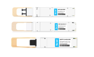
800G SR8 and 400G SR4 Optical Transceiver Modules Compatibility and Interconnection Test Report
Version Change Log Writer V0 Sample Test Cassie Test Purpose Test Objects:800G OSFP SR8/400G OSFP SR4/400G Q112 SR4. By conducting corresponding tests, the test parameters meet the relevant industry standards, and the test modules can be normally used for Nvidia (Mellanox) MQM9790 switch, Nvidia (Mellanox) ConnectX-7 network card and Nvidia (Mellanox) BlueField-3, laying a foundation for
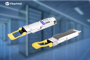
What is a Silicon Photonics Optical Module?
In the rapidly evolving world of data communication and high-performance computing, silicon photonics optical modules are emerging as a groundbreaking technology. Combining the maturity of silicon semiconductor processes with advanced photonics, these modules promise higher speeds, lower power consumption, and reduced costs. This in-depth guide explores the fundamentals, principles, advantages, industry

Key Design Principles for AI Clusters: Scale, Efficiency, and Flexibility
In the era of trillion-parameter AI models, building high-performance AI clusters has become a core competitive advantage for cloud providers and AI enterprises. This article deeply analyzes the unique network requirements of AI workloads, compares architectural differences between AI clusters and traditional data centers, and introduces two mainstream network design
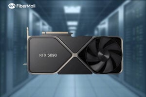
Google TPU vs NVIDIA GPU: The Ultimate Showdown in AI Hardware
In the world of AI acceleration, the battle between Google’s Tensor Processing Unit (TPU) and NVIDIA’s GPU is far more than a spec-sheet war — it’s a philosophical clash between custom-designed ASIC (Application-Specific Integrated Circuit) and general-purpose parallel computing (GPGPU). These represent the two dominant schools of thought in today’s AI hardware landscape.
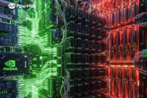
InfiniBand vs. Ethernet: The Battle Between Broadcom and NVIDIA for AI Scale-Out Dominance
The Core Battle in High-Performance Computing Interconnects Ethernet is poised to reclaim mainstream status in scale-out data centers, while InfiniBand continues to maintain strong momentum in the high-performance computing (HPC) and AI training sectors. Broadcom and NVIDIA are fiercely competing for market leadership. As artificial intelligence models grow exponentially in

From AI Chips to the Ultimate CPO Positioning Battle: NVIDIA vs. Broadcom Technology Roadmap Showdown
In the era driven by artificial intelligence (AI) and machine learning, global data traffic is multiplying exponentially. Data center servers and switches are rapidly transitioning from 200G and 400G connections to 800G, 1.6T, and potentially even 3.2T speeds. Market research firm TrendForce predicts that global shipments of optical transceiver modules
H3C S6550XE-HI Series 25G Ethernet Switch: High-Performance 25G/100G Solution for Campus and Metro Networks
The H3C S6550XE-HI series is a cutting-edge, high-performance, high-density 25G/100G Ethernet switch developed by H3C using industry-leading professional ASIC technology. Designed as a next-generation Layer 3 Ethernet switch, it delivers exceptional security, IPv4/IPv6 dual-stack management and forwarding, and full support for static routing protocols as well as dynamic routing protocols including