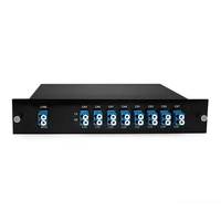

A DWDM link may fail to establish even when the transceivers are correctly matched and the fiber is clean. One possible cause lies between them: a passive DWDM mux demux with an incompatible channel plan, excessive insertion loss, or an incorrectly paired single-fiber configuration.
Channel count is often the first specification buyers compare. A 40-channel unit may look similar to another 40-channel unit until you examine its insertion loss, isolation, passband, and port options.
This guide takes a system-level approach. You’ll learn how a DWDM mux demux works, how TFF, AWG, and AAWG designs differ, how to choose between 4 and 96 channels, when single fiber is preferable to dual fiber, and how to evaluate the device against a practical optical power budget.
Sourcing a unit for a specific channel plan? Talk to FiberMall’s optical transport engineers before comparing prices.
What Is a DWDM Mux Demux and How Does It Work?
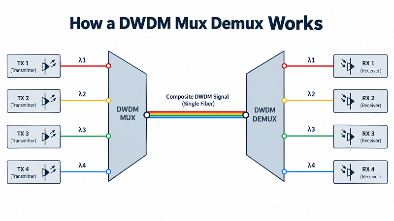
A DWDM mux demux is a passive optical device that combines multiple wavelengths defined by the ITU-T frequency grid onto a common fiber and separates them at the receiving end. DWDM, or Dense Wavelength Division Multiplexing, increases fiber capacity without requiring additional fiber cables. A passive mux demux requires no external power and is generally transparent to data rates and protocols.
The multiplexer sits at the transmitting end. It receives individual optical wavelengths through dedicated channel ports and combines them onto a common line port. The demultiplexer performs the reverse function at the receiving end, separating the wavelengths and directing them to their corresponding receivers.
The passive optical filters generally support bidirectional light propagation. Therefore, the same optical design can function as a multiplexer, a demultiplexer, or both, depending on the network architecture. In a typical dual-fiber bidirectional link, each end multiplexes outbound traffic onto one fiber and demultiplexes inbound traffic from the other.
However, data-rate transparency does not mean that every optical transceiver is automatically compatible. The transceiver wavelength, signal bandwidth, channel spacing, filter passband, and optical power budget must all be considered, particularly for higher-speed services.
Consider a regional ISP upgrading its metro network. The engineering team orders a 40-channel C21–C60 DWDM unit and uses optical transceivers operating on channel C30.
During installation, a transceiver is accidentally connected to the C29 port. Although the equipment is otherwise functioning correctly, the wavelength mismatch introduces substantial filtering loss, preventing the link from establishing.
Once the transceiver is connected to the correct C30 port, the wavelength mismatch is resolved. The lesson is simple: the transceiver wavelength must match the designated DWDM channel port.
Mux vs Demux: What’s the Difference?
A DWDM multiplexer combines multiple optical wavelengths onto a common fiber. A DWDM demultiplexer separates the combined signal into individual wavelengths. These are reverse optical functions, and the same passive filter design can generally perform either operation.
In practice, the distinction matters most at the ends of the link. A typical dual-fiber deployment can use identical mux/demux units at both ends. A passive single-fiber bidirectional deployment commonly uses complementary A/B units with different transmit and receive wavelength assignments.
The Ports You Will See
DWDM mux demux units may include several types of ports, depending on their design and intended application:
- Line port. The common optical port connecting the multiplexed channels to the transmission fiber. Some manufacturers label it COM.
- Channel ports. Individual ports assigned to specific ITU-grid wavelengths, each connected to a compatible optical transceiver.
- Expansion port. Allows compatible DWDM equipment to be cascaded to support additional wavelength channels. The supported wavelengths depend on the port’s filter characteristics.
- Upgrade port. Provides a reserved optical path for future services or additional channel groups. Manufacturers may use EXP and UPG labels differently, so the supported passband and intended application must be verified in the datasheet.
- Monitor port. Typically provides a 1% or 5% optical tap for monitoring composite optical power without interrupting the main transmission path.
- 1310 nm port. An optional pass-through port for compatible gray optical services, including certain 40G or 100G LR4/ER4 transceivers, without occupying a C-band DWDM channel.
- OTDR port. An optional monitoring or test port, commonly designed for out-of-band wavelengths such as 1625 nm or 1650 nm, depending on the product.
For the full transport picture, see the DWDM complete guide.
TFF vs AWG vs AAWG: Which DWDM Multiplexer Filter Fits?
The filter technology inside a DWDM mux demux affects channel density, insertion loss, physical size, temperature stability, and whether active thermal control is required.
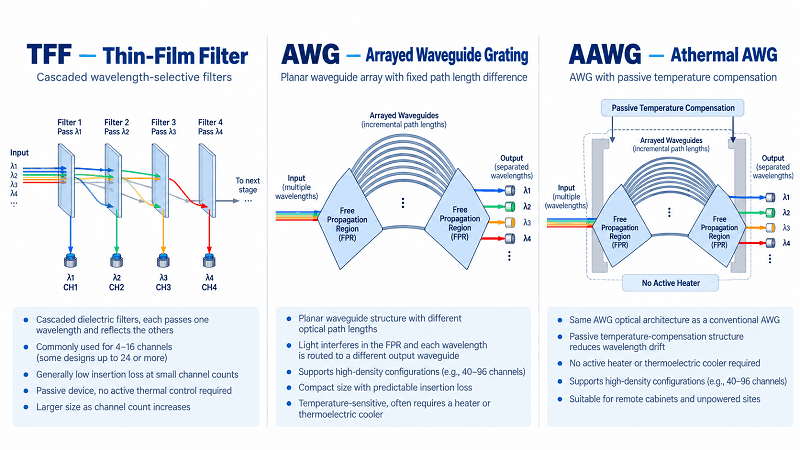
Thin-film filter (TFF) technology uses a cascade of dielectric optical filters. Each filter selectively transmits a designated wavelength band while reflecting other wavelengths toward subsequent filtering stages. TFF-based designs generally require no active thermal control and can provide low insertion loss and suitable passband characteristics.
TFF technology works particularly well for lower channel counts, commonly up to approximately 16 channels, although some designs support 24 or more. As channel counts increase, cascaded filter arrangements can become larger and may introduce additional cumulative insertion loss.
Arrayed waveguide grating (AWG) technology uses an integrated planar waveguide structure containing optical paths with precisely controlled length differences. Interference between these paths separates incoming wavelengths and directs them to corresponding output waveguides. AWG technology supports high-density configurations, commonly including 40, 80, and 96 channels, within a compact package. Its channel-dependent insertion loss can be characterized and accounted for during link design.
Conventional AWGs are sensitive to temperature changes and may require temperature stabilization, often using heaters or thermoelectric control. Athermal AWG (AAWG) technology uses passive temperature-compensation techniques to reduce wavelength drift without active thermal control. This makes AAWG devices particularly suitable for remote cabinets and locations without convenient electrical power.
| Technology | Typical Channels | Insertion Loss | Footprint | Best Fit |
| TFF | 4–16, sometimes 24 or more | Generally low at small channel counts; may increase with cascading | Larger at high channel counts | Low-count metro and access networks |
| AWG | Commonly 40–96 | Design-dependent and generally predictable | Compact | High-density optical terminals |
| AAWG | Commonly 40–96 | Design-dependent, with passive temperature compensation | Compact, no active heater required | Remote or unpowered sites |
However, AAWG is not necessarily the best choice for every deployment. For configurations with fewer than approximately 16 channels, TFF-based devices can offer advantages in cost, insertion loss, and simplicity. The optimal choice depends on channel count, optical specifications, environmental requirements, and total deployment cost.
Channel Count and Spacing: 4 to 96 Channels
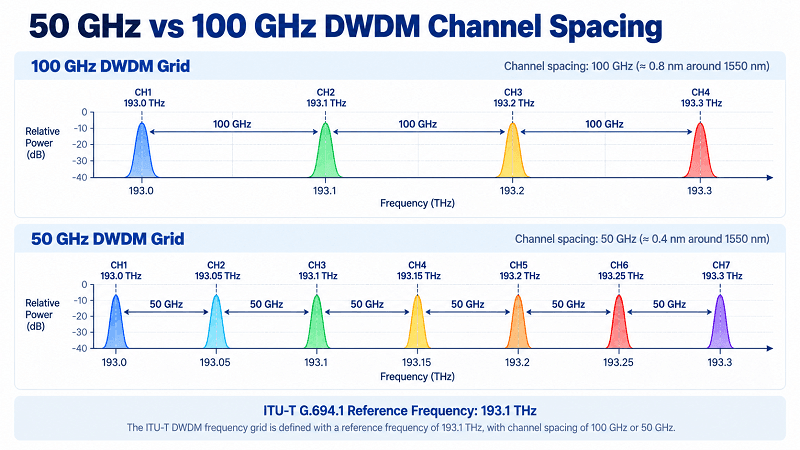
DWDM systems commonly use channel frequencies defined by ITU-T G.694.1, which specifies a frequency grid anchored at 193.1 THz. Around 1550 nm, a 100 GHz frequency spacing corresponds to approximately 0.8 nm in wavelength, while a 50 GHz spacing corresponds to approximately 0.4 nm.
The C-band generally covers approximately 1530–1565 nm and overlaps the primary operating range of erbium-doped fiber amplifiers (EDFAs). The L-band extends approximately from 1570 to 1610 nm and can provide additional spectral capacity when C-band resources are insufficient.
| Channels | Spacing | Typical Module Insertion Loss | Form Factor | Typical Use |
| 4 | 100 GHz | ≤1.8 dB | LGX or mini module | Small metro add/drop |
| 8 | 100 GHz | ≤3.2 dB dual-fiber; ≤4.8 dB single-fiber | LGX | Access and metro |
| 16 | 100 GHz | ≤4.0 dB | LGX or 1U | Metro ring |
| 40 | 100 GHz | Approximately 3.5–5.5 dB | 1U rack | Regional and long-haul |
| 80 | 50 GHz | Approximately 6–7 dB | Typically 1U or 2U | High-capacity DCI |
| 96 | 50 GHz | ≤7.0 dB for selected models | Typically 2U | High-density DWDM |
These values are representative examples rather than universal specifications. Actual insertion loss depends on the filter architecture, channel count, connector configuration, and optional ports. Monitor taps, expansion paths, and additional pass-through functions may introduce loss depending on their implementation. Always consult the datasheet for the exact model.
A common 40-channel, 100 GHz DWDM configuration covers channels C21 through C60. Certain 96-channel, 50 GHz products are specified across the frequency range labeled C15–C62, including intermediate 50 GHz channel positions between the conventional 100 GHz channel labels. Exact channel frequencies and wavelength assignments must be verified against the manufacturer’s channel map.
For future expansion, a practical planning approach is to reserve approximately 20% of the available channels where capacity and budget permit.
The choice between 50 GHz and 100 GHz spacing involves trade-offs. Within the same usable spectral range, a 50 GHz grid can accommodate approximately twice as many channel positions as a 100 GHz grid. However, narrower spacing requires tighter wavelength control, suitable optical filtering, and compatible transceiver signal spectra. A 100 GHz grid is generally easier to manage and remains sufficient for many metro and regional deployments.
Still deciding between coarse and dense spacing? The DWDM vs CWDM comparison explains the key technology trade-offs.
Single Fiber vs Dual Fiber DWDM: Which Configuration Fits?
Fiber availability often determines the preferred architecture, but equipment costs, wavelength planning, and spare-unit requirements also affect the decision.
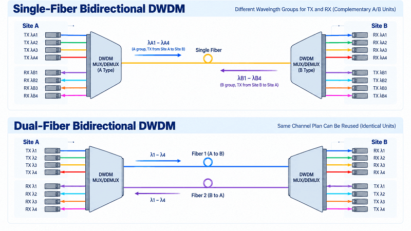
A dual-fiber configuration uses two optical fibers, typically one for each transmission direction. Both directions can reuse the same wavelength assignments because they travel over separate fibers. This enables the use of identical mux/demux configurations at both ends. Dual-fiber DWDM is widely deployed because it simplifies installation, maintenance, and troubleshooting.
A single-fiber configuration uses one optical fiber. It can support unidirectional transmission or bidirectional communication, depending on the system architecture. In a typical passive single-fiber bidirectional DWDM design, separate wavelength groups are assigned to opposite transmission directions, and complementary A/B units route the wavelengths correctly.
For example, an 8-channel single-fiber bidirectional module may use 16 wavelengths in total, with eight assigned to transmission in one direction and eight assigned to the opposite direction. The complementary A/B units reverse these wavelength assignments at the two ends.
This configuration provides eight bidirectional wavelength pairs rather than 16 independent bidirectional channels.
| Configuration | Fibers | Wavelength Use | Units at Each End | Best For | Watch Out |
| Dual fiber | 2 | Same channel wavelengths can be reused in both directions | Typically identical units | Most deployments | Requires two fiber strands |
| Single fiber, bidirectional | 1 | Separate wavelength groups for opposite directions | Complementary A/B units in typical passive designs | Fiber-constrained routes | More complex wavelength planning and spares |
| Single fiber, unidirectional | 1 | One transmission direction only | Compatible mux and demux arrangement | Broadcast or one-way monitoring | No return path on the same link |
Single-fiber configurations reduce fiber consumption but do not necessarily reduce overall deployment costs. Bidirectional single-fiber systems require careful wavelength planning and may require separate A/B spare units. They are particularly valuable when fiber availability is limited or additional fiber leasing is expensive.
When sufficient fiber capacity is available, dual-fiber DWDM generally offers simpler deployment and maintenance.
At intermediate nodes in a DWDM ring, a passive optical add-drop multiplexer (OADM) can add or drop selected wavelengths while allowing other wavelengths to pass through. This differs from a terminal mux/demux, which typically combines or separates the complete set of configured channels at an endpoint.
DWDM Mux Demux Specs That Decide Your Optical Budget
Insertion loss is one of the most important specifications affecting DWDM link performance. It represents the optical power lost as a signal passes between a channel port and the common line port.
Insertion loss depends on the filter technology, optical path, channel configuration, connectors, and optional functions. Although cascaded TFF designs may exhibit increasing loss as channel counts grow, high-density AWG and AAWG designs do not necessarily follow the same trend.
A 4-channel unit may specify insertion loss of 1.8 dB or less. An 8-channel unit may specify 3.2 dB or less, while a 16-channel unit may specify 4.0 dB or less. Certain 48-channel designs may specify insertion loss around 5.5 dB, depending on their construction.
FiberMall’s low-loss 40-channel 1U DWDM mux demux is rated at 3.5 dB or less per unit, corresponding to a maximum of approximately 7 dB for a matched mux/demux pair. The 96-channel 50 GHz model is rated at 7.0 dB or less per unit.
Worked 80 km Link-Budget Example
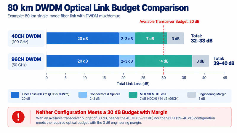
Consider an 80 km optical span using standard G.652 single-mode fiber. Assuming an attenuation of approximately 0.25 dB/km at 1550 nm, the fiber contributes about 20 dB of loss. Connectors and splices may introduce another 2–3 dB, depending on the installation.
Next, include the mux/demux insertion loss. A pair of low-loss 40-channel units contributes up to approximately 7 dB, while a pair of 96-channel units rated at 7 dB each can contribute up to 14 dB.
With an additional 3 dB engineering margin, the estimated optical power budget requirements are:
| Loss Component | 40CH DWDM | 96CH DWDM |
| Fiber attenuation (80 km) | 20 dB | 20 dB |
| Connectors and splices | 2–3 dB | 2–3 dB |
| Mux + demux insertion loss | 7 dB | 14 dB |
| Engineering margin | 3 dB | 3 dB |
| Total required budget | 32–33 dB | 39–40 dB |
This difference significantly affects link feasibility. If the transceiver’s available optical power budget is only 30 dB, neither configuration meets the calculated requirement with the specified engineering margin.
The 40-channel design requires approximately 32–33 dB, while the 96-channel design requires approximately 39–40 dB under these assumptions.
Possible solutions include reducing the transmission distance, selecting lower-loss optical components, choosing transceivers with a suitable optical budget, or introducing optical amplification where technically appropriate.
However, adding an EDFA is not always a complete solution. The design must also account for optical signal-to-noise ratio (OSNR), receiver input power limits, chromatic dispersion, nonlinear effects, and amplifier operating conditions.
Consider a data center interconnect project connecting two facilities over an 80 km fiber span. The engineering team selects 96-channel DWDM mux/demux units to maximize future capacity. Although the optical transceivers are specified for an 80 km application, the additional mux/demux loss reduces the available system margin.
A detailed budget calculation reveals that the mux/demux pair alone may introduce up to 14 dB of additional loss. Depending on the transceiver characteristics and overall transmission design, an appropriately engineered amplification solution or lower-loss filtering configuration may be necessary.
The key lesson is that a transceiver’s nominal reach does not guarantee the same reach after additional passive DWDM components are inserted into the optical path.
Isolation, PDL, Return Loss, and Passband
Insertion loss receives considerable attention, but several other optical parameters are equally important for reliable DWDM operation.
Adjacent-channel isolation describes how effectively a filter suppresses signals from neighboring wavelength channels. Values around 25–30 dB or higher are common design targets, depending on channel spacing and equipment specifications. Insufficient isolation can increase inter-channel crosstalk.
Non-adjacent-channel isolation is often specified at higher values, commonly around 30–40 dB or more, depending on the optical filter architecture.
Polarization-dependent loss (PDL) describes how insertion loss varies with the polarization state of the optical signal. Low-PDL designs may specify values around 0.2–0.5 dB, while certain high-density AAWG products may allow higher values. For example, specifications can vary from approximately 0.3 dB for selected low-loss designs to 0.8 dB for some 96-channel AAWG configurations. Always use the maximum PDL value specified for the actual product when evaluating system performance.
Return loss indicates the amount of optical power reflected back toward the source. Values of 40–45 dB or higher are commonly desirable, although specific requirements depend on the system and optical components. Excessive reflections can impair laser stability and transmission performance.
Passband characteristics determine the optical frequency range that each channel can transmit with acceptable attenuation and distortion. For example, a nominal 60 GHz passband on a 100 GHz grid may support certain combinations of 10G and 40G services, provided their signal spectra and wavelength tolerances remain within the usable filter bandwidth.
However, nominal passband width alone does not guarantee compatibility with every high-speed transceiver. Modulation format, spectral occupancy, wavelength drift, passband shape, and cascaded filtering effects must also be considered.
The unit must also support the optical power levels and environmental conditions of the installation. Some products specify maximum optical power levels in the range of several hundred milliwatts and operating temperatures such as -5°C to +70°C, but these values are product-specific. Always verify the maximum input power, operating temperature, and storage temperature against the transceivers and installation environment.
How to Choose a DWDM Mux Demux: 7-Step Framework
The selection process should begin with channel requirements and the optical budget before narrowing down the hardware options.
- Count the required channels and allow for growth. Start with the number of wavelengths needed today and consider reserving approximately 20% spare capacity. For example, a 40-channel unit can accommodate 32 active channels while leaving eight available for future expansion.
- Choose the channel grid. A 100 GHz grid is commonly used for systems with approximately 40 channels or fewer and can simplify wavelength management. A 50 GHz grid is suitable for higher-density configurations, such as 80 or 96 channels, provided the transceivers and filters support the required spacing.
- Select the filter technology. Consider TFF for lower channel counts, particularly below approximately 16 channels. AWG and AAWG technologies are generally more suitable for high-density configurations such as 40–96 channels.
- Determine the fiber architecture. Choose dual fiber for simpler bidirectional communication when two fiber strands are available. Consider single-fiber bidirectional DWDM when fiber resources are limited or expensive, while accounting for wavelength pairing and A/B unit requirements.
- Calculate the optical budget. Include fiber attenuation, connector and splice losses, mux/demux insertion loss, and engineering margin. Compare the total with the available optical power budget of the transceivers. For longer or higher-speed links, evaluate additional parameters such as OSNR and dispersion.
- Choose the required ports and options. Determine whether the deployment requires expansion, upgrade, monitoring, 1310 nm pass-through, or OTDR functionality. Verify the wavelength ranges and insertion-loss specifications of each optional port.
- Select the packaging and connectors. LGX modules are suitable for compact installations, while 1U and 2U rack-mounted units support larger channel configurations. LC/UPC connectors are widely used in data centers, while SC and FC connector options remain available for telecom applications.
FiberMall’s DWDM mux demux portfolio includes several commonly deployed configurations:
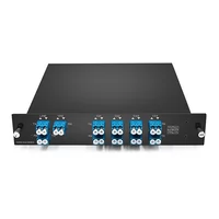
- 8-Channel Single-Fiber DWDM Mux Demux: This LGX unit uses wavelength channels within the C43–C58 range in a complementary transmit/receive arrangement on a 100 GHz grid. It supports eight bidirectional wavelength pairs, specifies insertion loss of 4.8 dB or less, and includes a monitor port.
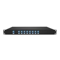
- 40-Channel Low-Loss DWDM Mux Demux: This 1U unit supports channels C21–C60 on a 100 GHz grid, with insertion loss of 3.5 dB or less. It also includes a 1310 nm pass-through port and a 1% monitor port.
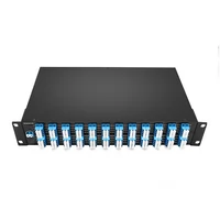
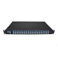
- 96-Channel 50 GHz DWDM Mux Demux: This 2U high-density unit covers a 96-channel frequency plan commonly designated C15–C62, including intermediate 50 GHz channel positions. It specifies insertion loss of 7.0 dB or less and includes an expansion port.
Need help evaluating the optical budget? Share your fiber span length, channel requirements, and transceiver specifications with FiberMall’s engineering team for a detailed link-loss assessment before ordering.
Pricing depends on several factors. Channel count, channel spacing, and filter architecture influence component costs. Low-loss specifications may require more advanced optical designs and can increase pricing.
Single-fiber bidirectional configurations may also involve additional costs for complementary A/B equipment and wavelength planning. Optional monitor, 1310 nm, and OTDR ports can affect pricing, while custom channel plans and additional testing documentation may extend lead times.
Installation, Testing, and Troubleshooting
Successful DWDM commissioning depends on systematic verification and testing. Before activating the optical links, confirm the channel plan, wavelength assignments, and transmit/receive pairing. Inspect and clean all fiber connector end faces using appropriate inspection and cleaning tools, and verify that connector types and polish specifications match the equipment ports.
Measure the optical power through the monitor port when available. Because monitor ports typically use a defined optical tap ratio, the measured power must be corrected according to the manufacturer’s specified monitoring characteristics before estimating the main-line power.
For example, a nominal 1% monitoring tap corresponds to approximately 20 dB of power difference between the tapped signal and the reference signal under ideal conditions. Actual measurements must account for specified tap tolerances and additional losses.
To evaluate mux/demux insertion loss, measure optical power at the relevant channel and line ports under controlled test conditions. Use an optical power meter with a suitable wavelength source or an optical spectrum analyzer when channel-specific measurements are required.
If the measured values deviate significantly from the expected specifications, inspect and clean the connectors, verify patch-cord routing, and check transceiver wavelength compatibility before concluding that the mux/demux is defective.
Watch for these common failures:
- A transceiver operating on channel C30 is connected to the C29 port, creating a wavelength mismatch.
- A single-fiber unit is paired with an incorrect or incompatible A/B counterpart.
- An expansion port is used for a wavelength group that requires a different upgrade or pass-through port configuration.
- Contaminated or damaged connectors introduce excess insertion loss that resembles an equipment failure.
- A high-density 96-channel mux/demux pair introduces more loss than the available optical power budget can support.
FAQ
What is the difference between a DWDM mux and demux?
A DWDM multiplexer combines multiple optical wavelengths onto a common fiber, while a demultiplexer separates the combined wavelengths at the receiving end. Passive DWDM filters generally support bidirectional optical propagation, allowing compatible devices to perform either function.
How many channels does a DWDM mux/demux support?
Common configurations include 4, 8, 16, 40, 80, and 96 channels. The supported channel count depends on channel spacing, available optical spectrum, and filter technology. A conventional 100 GHz C-band system commonly supports approximately 40 channels, while 50 GHz systems can support 80 or 96 channels with appropriate channel planning.
What is the difference between 50 GHz and 100 GHz DWDM?
A 100 GHz DWDM grid provides approximately 0.8 nm wavelength spacing near 1550 nm, while a 50 GHz grid provides approximately 0.4 nm. A 50 GHz grid allows higher channel density within the same usable frequency range but requires tighter wavelength control and filters compatible with narrower channel spacing.
Should I choose single-fiber or dual-fiber?
Dual-fiber DWDM is generally preferable when two fiber strands are available because it simplifies installation, wavelength management, maintenance, and spare-unit planning. Single-fiber bidirectional DWDM is suitable when fiber availability is limited, but it requires compatible wavelength assignments and complementary A/B equipment in typical passive designs.
What insertion loss should I expect?
Insertion loss varies by channel count, filter technology, and product design. Representative values include 1.8 dB or less for certain 4-channel units, 3.2 dB or less for selected 8-channel dual-fiber units, and 4.0 dB or less for some 16-channel units. A low-loss 40-channel unit may specify 3.5 dB or less, while a 96-channel AAWG unit may specify up to 7.0 dB. Always verify the exact datasheet values, including optional port losses.
Can I mix 10G and 100G on one DWDM mux?
Yes, provided the optical signals use compatible wavelengths and their spectral characteristics fit within the DWDM filter passbands. Passive DWDM mux/demux devices are generally transparent to data rates and protocols, but not every 100G optical interface is suitable for direct transmission through a standard DWDM channel.
The modulation format, signal bandwidth, channel spacing, and optical power budget must be considered. A dedicated 1310 nm pass-through port can also support certain compatible gray 40G or 100G services without using a C-band DWDM channel.
Do I need an EDFA with a passive DWDM mux?
Not necessarily. Many shorter metro links can operate without optical amplification when the transceivers provide sufficient optical power budget. Longer spans or configurations with higher insertion loss may require amplification. However, EDFA selection should account for OSNR, receiver power limits, amplifier gain, channel loading, and overall transmission performance.
What is the 1310 nm port used for?
A 1310 nm pass-through port allows compatible gray optical signals, including certain 40G or 100G LR4/ER4 transceivers, to share the same fiber infrastructure without occupying a C-band DWDM channel.
Compatibility depends on the pass-through port’s supported wavelength range, insertion loss, optical power handling, and the transceiver’s optical specifications. For example, a port designed for approximately 1260–1360 nm operation may support suitable 1310 nm-band services, provided the complete optical link budget remains acceptable.
Conclusion
A DWDM mux demux is more than a passive fiber connection device. It introduces insertion loss, establishes wavelength-channel requirements, and influences the choice of fiber architecture and optical transmission equipment.
A reliable selection process starts by determining the required channel count, choosing the appropriate frequency grid, selecting TFF, AWG, or AAWG filter technology, deciding between single-fiber and dual-fiber architectures, and verifying the optical budget before comparing equipment prices.
This approach helps prevent common deployment problems, including wavelength mismatches, excessive insertion loss, and insufficient optical power margin.
FiberMall offers 8-, 40-, and 96-channel DWDM mux demux configurations, along with custom wavelength-channel plans for specific network requirements. Share your fiber span length, channel count, transceiver specifications, and future expansion plans with our engineering team for a suitable solution.
Related Products:
-
 DWDM MUX DEMUX 50GHZ 96CH (C15-C62) LC/UPC Dual Fiber 2U Rack
$6000.00
-
DWDM MUX DEMUX 40CH (C21-C60) LC/UPC Dual Fiber 1U Rack
$1100.00
-
DWDM MUX DEMUX 16CH (C21-C36) with Monitor Port LC/UPC Dual Fiber 1U Rack
$800.00
-
DWDM MUX DEMUX 8CH (C21-C28) with Express Port LC/UPC Dual Fiber LGX BOX
$500.00
-
DWDM MUX 8CH 16 Wavlengths (TX: C43/C45/C47/C49/C51/C53/C55/C57 RX: C44/C46/C48/C50/C52/C54/C56/C58) with MON Port LC/UPC Single Fiber LGX BOX
$450.00
-
SFP-DW10G17-40C 10G DWDM SFP+ C17 100GHz 1563.86nm 40km LC SMF DDM Transceiver Module
$155.00
-
SFP-DW10G17-80C 10G DWDM SFP+ C17 100GHz 1563.86nm 80km LC SMF DDM Transceiver Module
$175.00
-
SFP-DW10G17-100C 10G DWDM SFP+ C17 100GHz 1563.86nm 100km LC SMF DDM Transceiver Module
$235.00
-
SFP-DW10GTU-40C 10G DWDM Tunable SFP+ 50GHz 1529.55nm~1561.83nm 40km LC SMF DDM Transceiver Module
$550.00
-
SFP-DW10GTU-80C 10G DWDM Tunable SFP+ 50GHz 1529.55nm~1561.83nm 80km LC SMF DDM Transceiver Module
$750.00
-
OSFP-400G-DCO-ZR 400G Coherent OSFP-DCO ZR C-band Tunable Optical Transceiver Module
$7000.00
-
OSFP-400G-DCO-ZR+ 400G Coherent OSFP-DCO ZR+ C-band Tunable Optical Transceiver Module
$7000.00
-
OSFP-800G-DCO-ZR+-HTx 800G Coherent High TX Power OSFP DCO ZR+ C-band Tunable Optical Transceiver Module
$12000.00
-
OSFP-800G-DCO-ZR-HTx 800G Coherent High TX Power OSFP DCO ZR C-band Tunable Optical Transceiver Module
$11000.00
-
QSFP-DD-400G-DCO-ZR 400G Coherent QSFP-DD DCO C-band Tunable Optical Transceiver Module
$4550.00
-
QSFP-DD-400G-DCO-ZR+ 400G Coherent QSFP-DD DCO C-band Tunable Optical Transceiver Module
$4680.00
-
QSFP-DD-400G-DCO-ZR+-HTx 400G Coherent High TX Power QSFP-DD DCO OpenZR+ C-band Tunable Optical Transceiver Module
$5500.00
-
QSFP-DD-400G-DCO-ZR-HTx 400G Coherent High TX Power QSFP-DD DCO ZR C-band Tunable Optical Transceiver Module
$5200.00