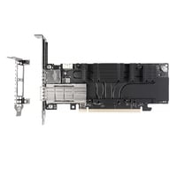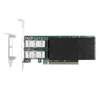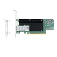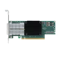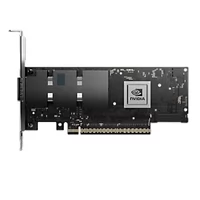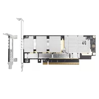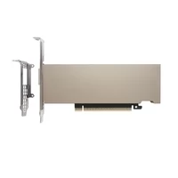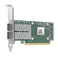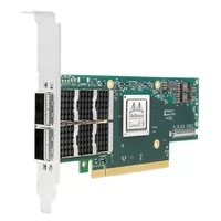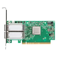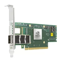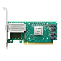

A network interface card (NIC) is the adapter that connects a server or computer to a network. Choose a NIC based on four factors, in this order: port speed, port count, PCIe lane budget, and the optics or cables the port supports. Mistakes in the last two decisions can cost more than the card itself.
That ordering isn’t the way most guides present it. Product listings lead with the controller name and headline speed because those are the easiest things to compare. But a NIC must match both the host’s PCIe capabilities and the network’s cabling infrastructure.
Get the slot wrong and you throttle a card you paid for. Get the cage wrong and a module you already own won’t seat.
This guide works through all four decisions from 1GbE to 800Gb/s networking. It’s written for engineers specifying server hardware, so it favors lane counts, cage standards, and reach tables over definitions. Where a number matters, the number is here.
Key Takeaways
- Port speed, port count, PCIe lane budget, and cage type are the four key decisions. Cage compatibility is often overlooked.
- A dual-100G card typically needs PCIe Gen4 x16; a single 100G port may fit Gen3 x16; and a dual-25G card generally fits Gen3 x8. Always check the adapter and server specifications.
- Many NIC deployment problems occur at the optical and cabling layer: unsupported modules, incorrect MPO polarity, and breakout plans with the wrong fiber count.
- FiberMall’s listed NIC range spans 1G to 800G-class connectivity, including the ConnectX-8, which supports 800Gb/s InfiniBand XDR or configurable 2×400GbE.
- Price the port and its media, not just the card. Fiber count depends on the optical PMD: common 100G optics use 2 or 8 fibers, while 400G and 800G designs can use different counts.
What Is a Network Interface Card?
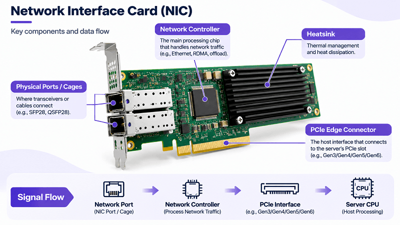
A network interface card is the hardware that lets a host communicate with a network. It contains a network controller, MAC and PHY functions, one or more physical cages, and a host interface such as PCIe or an OCP connector. The controller processes network traffic; the cage is where a transceiver or cable connector plugs in.
Every network interface card you buy for a server resolves to those four parts. What changes between cards is how fast each part runs and what the cage accepts.
That last part deserves emphasis because it’s where specifications get vague. A product page might say “dual-port 25G SFP28.” Read literally, that tells you three things: two ports, 25G per port, and SFP28 cages. It doesn’t tell you the PCIe lane requirement, whether the card is Gen3 or Gen4, or which 25G modules the firmware will accept. Those three unknowns decide whether the card works in your chassis.
A network card also has a firmware and driver compatibility profile. Optical transceivers carry EEPROM identification data, including vendor and part information. Some host platforms accept third-party modules, while others may flag or reject them based on vendor-specific compatibility checks.
This isn’t just a marketing detail. It can become a compatibility issue during installation.
If you’d rather compare adapter types than work through selection logic, our fiber network card guide covers SFP-based adapters in more detail.
NIC Port Speeds From 1GbE to 800GbE
A network card’s speed is set by the port, not by the controller’s peak rating, so the port is the first thing to check.
The table below gives representative host-side electrical lane configurations and common optical PMDs. The electrical lane count is not necessarily the same as the optical lane count, and fiber count depends on the specific PMD.
| Speed | Typical host-side electrical lanes | Typical cage | Media | Common optical PMDs / cable types | Typical optical fiber count |
| 1G | 1 × 1.25 Gb/s NRZ | SFP | Copper or fiber | 1000BASE-T, SX, LX, EX | 2 for SX/LX/EX (duplex LC); copper uses RJ45 |
| 10G | 1 × 10.3125 Gb/s NRZ | SFP+ | Fiber, DAC, or AOC | 10GBASE-SR, LR, ER | 2 for optical links (duplex LC) |
| 25G | 1 × 25.78125 Gb/s NRZ | SFP28 | Fiber, DAC, or AOC | 25GBASE-SR, LR | 2 for optical links (duplex LC) |
| 40G | 4 × 10.3125 Gb/s NRZ | QSFP+ | Fiber, DAC, or AOC | 40GBASE-SR4, LR4 | 8 for SR4 (MPO-12); 2 for LR4 (duplex LC) |
| 100G | Typically 4 × 25.78125 Gb/s NRZ for QSFP28 | QSFP28 | Fiber, DAC, or AOC | 100GBASE-SR4, LR4, ER4; DR1 variants | 8 for SR4; 2 for LR4/ER4/DR1 (legacy SR10 uses 20) |
| 200G | 4 × 50 Gb/s PAM4 | QSFP56 | Fiber, DAC, or AOC | 200GBASE-SR4, DR4, FR4 | 8 for SR4/DR4; 2 for FR4 |
| 400G | 8 × 50G or 4 × 100G PAM4, depending on host interface | QSFP-DD or OSFP | Fiber, DAC, or AOC | 400GBASE-SR8, DR4, FR4, LR4-6 / LR4-10 | 16 for SR8; 8 for DR4; 2 for FR4/LR4 |
| 800G | 8 × 100G Ethernet lanes or 4 × 200G XDR IB lanes, depending on protocol | QSFP-DD800 or OSFP | Fiber, DAC, or AOC | 800GBASE-SR8, DR8, 2×FR4 / 2×LR4 | 16 for SR8/DR8; 4 for 2×FR4/2×LR4 |
Three things in that table are worth pausing on.
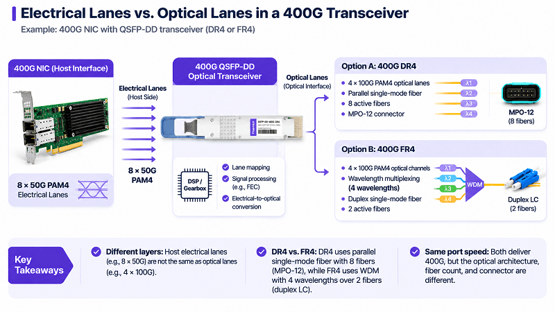
First, host-side electrical lanes and optical lanes must be treated separately. A QSFP28 100G interface commonly uses four 25G NRZ electrical lanes, while a 100G DR1 optical interface uses one 100G PAM4 optical lane. At 400G, a host interface using eight 50G PAM4 electrical lanes can connect to a DR4 or FR4 optical interface using four 100G PAM4 optical lanes. The exact mapping depends on the NIC, module, and PMD.
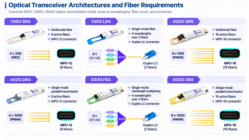
Second, fiber count does not increase in a simple one-to-one relationship with port speed. A 100G SR4 link uses eight fibers, while common 100G LR4 and DR1 links use two. A 400G SR8 link uses 16 fibers, DR4 uses eight, and FR4 uses two. An 800G SR8/DR8 link typically uses 16 fibers, while 2×FR4 uses four. Check the PMD and connector before sizing trunks and patch panels.
Third, the cage column is where mechanical backward compatibility matters. SFP, SFP+, and SFP28 share a form factor, so many SFP28 ports can accept a 10G SFP+ module when the host supports 10G operation. QSFP+, QSFP28, and QSFP56 also share a form factor. QSFP-DD cages are designed to accept earlier QSFP-family modules, subject to host support and configuration.
OSFP is a different, larger form factor and does not directly accept QSFP-family modules.
Note: Mechanical compatibility is necessary but not sufficient. A port may physically accept a module and still reject it in firmware or fail to support its speed, FEC mode, or link configuration. Check the datasheet for the specific NIC and module.
Our 10G and 25G adapter category and the 40G and 100G QSFP range both list the exact cage and PCIe generation for each card.
The Port Is Not the Pipe: PCIe Lanes and Real Throughput
A NIC can only move as much data as its host slot allows. That sounds obvious. What is less obvious is that the lane arithmetic is rarely published, so teams buy by headline speed and discover the mismatch after install.
Approximate PCIe bandwidth per lane, per direction (before transaction-layer overhead):
| Generation | Per lane | x8 total | x16 total | Encoding |
| Gen3 | ~985 MB/s | ~7.9 GB/s | ~15.8 GB/s | 128b/130b |
| Gen4 | ~1.97 GB/s | ~15.8 GB/s | ~31.5 GB/s | 128b/130b |
| Gen5 | ~3.94 GB/s | ~31.5 GB/s | ~63 GB/s | 128b/130b |
| Gen6 | ~7.88 GB/s | ~63 GB/s | ~126 GB/s | PAM4, FLIT, FEC/CRC |
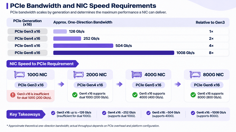
Converting those figures to network units gives the following practical guidelines. Compare the NIC’s aggregate one-direction port bandwidth with the PCIe bandwidth available in the same direction:
- Dual 25G (50 Gb/s aggregate) fits in Gen3 x8 (about 63 Gb/s). This leaves roughly 20% of the PCIe link capacity unused before transaction-layer overhead.
- A single 100G port can fit in Gen3 x16 (about 126 Gb/s), although the margin is limited. Check the NIC manufacturer’s recommended slot configuration.
- Dual 100G (200 Gb/s aggregate) exceeds Gen3 x16 and generally requires Gen4 x16 (about 252 Gb/s).
- A 400G port requires Gen5 x16 (about 504 Gb/s) as a practical minimum. Gen4 x16 does not provide enough one-direction bandwidth.
- An 800G port requires Gen6 x16 (about 1,008 Gb/s using the approximate figure in the table). Gen5 x16 is insufficient.
A common failure mode is installing a faster-generation card in a slower-generation slot. A Gen4 card installed in a Gen3 slot typically negotiates at Gen3, reducing the available PCIe bandwidth. The system may still boot normally, but the host link can bottleneck the NIC when aggregate traffic exceeds the slot’s capacity.
A realistic example is a dual-port 100G card installed in a Gen3 x16 slot. The two network ports offer 200 Gb/s of aggregate one-direction bandwidth, but the PCIe link provides only about 126 Gb/s. Under sustained aggregate load, the host interface can become the bottleneck. The remedy is a Gen4-capable path—including the CPU root port, motherboard, and riser—or a lower aggregate port configuration. A riser alone cannot upgrade a Gen3 root port to Gen4.
One practical check before ordering: confirm the slot’s generation, not just its width. An x16 Gen3 slot and an x16 Gen4 slot can look identical from outside the chassis.
Do you need a x16 card for 25G?
No. A dual-25G network interface card generally runs comfortably in an x8 Gen3 slot, provided the card and server support that configuration. This can leave an x16 slot available for a higher-bandwidth adapter later.
Matching the Optic to the Port
This is the section most NIC guides omit, and it’s where the money and the failures are. A port speed tells you what the card can do. The cage and the optic tell you what it can connect to, over what distance, for what cost.
For a server build, the module choice often costs more than the network interface card itself once you count one module per port plus the fiber between them.
Coded modules and vendor firmware
Optical transceivers typically carry EEPROM identification data such as vendor name, OUI, part number, and supported capabilities. Some NIC platforms use firmware or driver policies to check this information and may flag or reject unsupported third-party modules. Other platforms are more permissive. Compatibility behavior varies by NIC model, firmware, driver, and module.
A common symptom is a port that remains down or reports an unsupported-transceiver warning even though the module is seated and the link partner is operating normally. However, a link-down condition can also have other causes, including FEC mismatch, speed configuration, fiber polarity, or a faulty cable.
The practical options are to order modules configured for the target platform or, where supported, to use a module with an appropriate compatibility profile. Reprogramming can improve compatibility, but it is not a universal guarantee or a substitute for checking the platform requirements. This is the purpose of FiberMall’s coding service.
When requesting coding, provide the exact NIC or switch model, firmware/software version where relevant, target port speed, and module part number—not just the vendor name. Some platforms check more than a top-level vendor identifier.
Reach selection by speed
Reach is set by the module, and the module options narrow as speed rises. The table below lists representative reaches for common data-center optics. Exact reach depends on the PMD, fiber grade, channel loss, and product specification; check the datasheet for the specific part.
| Speed | Short reach | Mid reach | Long reach |
| 10G | SR: 300 m OM3, 400 m OM4 | LR: 10 km | ER: 40 km |
| 25G | SR: 70 m OM3, 100 m OM4 | LR: 10 km | ER: uncommon |
| 40G | SR4: 100 m OM3, 150 m OM4 | LR4: 10 km | ER4: 40 km |
| 100G | SR4: 70 m OM3, 100 m OM4; DR1: 500 m SMF | LR4: 10 km | ER4: 40 km |
| 400G | SR8: about 100 m OM4; DR4: 500 m | FR4: 2 km | LR4-6: 6 km; LR4-10 MSA variants: 10 km |
| 800G | SR8: about 100 m OM4; DR8: 500 m | FR4: 2 km | LR4: 10 km (where supported) |
Two patterns matter here. First, multimode reach generally decreases as signaling rates and PMD requirements increase. For example, 10GBASE-SR can reach 400 m on OM4, while 100GBASE-SR4 is typically limited to 100 m on OM4. If your campus or lab was built around OM3/OM4 for 10G, do not assume the same cabling plant will support the same distances at 100G.
Second, reach and fiber type depend on the PMD architecture, not simply the number of lanes. At 400G, SR8 uses parallel multimode fiber, DR4 uses parallel single-mode fiber, and FR4/LR4 use wavelength multiplexing over duplex single-mode fiber. Do not compare SR8 and LR4 as if they were two single-mode options.
DAC, AOC, or optic: the cost crossover
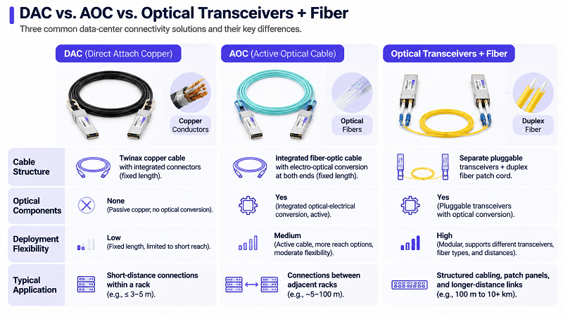
Within a row, the choice between copper and optics is a distance and cost decision.
Direct attach copper (DAC) is often the lowest-cost option for very short links, typically up to about 3 m for passive DAC and around 5 m for active DAC at 100G, depending on the product. It contains no optical components and does not require separate optical transceivers or optical-module burn-in. However, many DAC assemblies include EEPROM identification, and some platforms apply vendor-compatibility checks to cables as well.
DAC is also thick and inflexible, which matters in dense racks.
Active optical cables (AOC) are fiber with fixed ends. They reach further than DAC (commonly 20 to 100 m at 100G), bend more easily, and are immune to EMI. AOC costs more than DAC and less than a pair of modules plus a patch cord at short distances.
Modules plus fiber are the flexible option and the right answer once you cross into structured cabling, patch panels, or any link you might repatch. They cost the most per link at short distances and the least per link once you are sharing trunk fiber across many ports.
The crossover isn’t a fixed number, because it depends on your fiber plant and whether the module is coded. As a working rule, DAC wins inside a rack, AOC wins between adjacent racks up to about 30 m, and modules win beyond that or wherever you need structured cabling. The DAC and AOC category lists reach and gauge for each cable.
Breakout and fiber budget
High-speed ports can sometimes be split into lower-speed links. For example, a supported 400G port may be configured as 4×100G using a compatible breakout cable or breakout module. This is useful for connecting a high-density leaf port to four 100G servers. The NIC, switch, firmware, driver, transceiver, and cable must all support the intended breakout mode and lane mapping.
Breakout changes the cabling plan. A 400G DR4 optical interface uses four 100G optical lanes and eight active fibers in an MPO-12 connector. A compatible breakout harness maps those fibers into four duplex pairs. The total active fiber count remains eight, but the connector layout, patch-panel mapping, and polarity plan change. MPO polarity errors—where transmit and receive paths are not mapped correctly end to end—are a common cause of physical-link failures in new builds.
Warning: Confirm polarity method (A, B, or C) for every MPO run before ordering trunk cables. A polarity mismatch produces the same symptom as a dead module and is harder to diagnose.
Ethernet, InfiniBand, SmartNIC, and DPU
Four card families appear in server specifications, and they aren’t interchangeable.
- Ethernet NICs carry Ethernet traffic, including TCP/IP. When an application needs RDMA over Ethernet, RoCEv2 encapsulates RDMA transport over UDP/IP and Ethernet; it is not a separate physical fabric alongside Ethernet and InfiniBand. Most data-center servers use Ethernet NICs, and the selection logic above applies directly.
- InfiniBand host channel adapters communicate over an InfiniBand fabric rather than Ethernet. They are common in AI and HPC clusters where the fabric is dedicated to GPU-to-GPU or other high-performance traffic. A card marketed as “VPI” (virtual protocol interconnect) may support either Ethernet or InfiniBand mode, depending on the model and configuration. Our InfiniBand optics collection covers the matching cable and module side.
- SmartNICs add programmable or specialized processing that can offload work from the host CPU, such as virtual switching, encryption, or storage processing. The value depends on the workload. A general-purpose web server may not benefit unless it has a specific offload requirement; a telco NFV host or a hypervisor running dense virtual switching may benefit substantially.
- DPUs extend the SmartNIC concept with an onboard compute complex, memory, and software environment. NVIDIA’s BlueField-3 is one example, and the company’s DOCA documentation describes its programming model.
The selection question for a SmartNIC or DPU isn’t simply “is it faster?” It is “does the offload justify the added cost and operational complexity?” A DPU often costs more than a conventional NIC, adds a software stack to maintain, and needs a workload that can use its offload engines. For general-purpose servers, the benefit may be limited; for AI clusters, storage systems, or virtualized network functions with tight CPU budgets, it can be substantial.
If the boundary between these categories is unclear for your design, our SmartNIC vs NIC comparison walks through where the offload line sits.
How to Choose a Network Interface Card for a Server
Work the six steps in order. Each one constrains the next.
- Workload and protocol. Decide whether the fabric will use Ethernet or InfiniBand. If you choose Ethernet and need RDMA, determine whether RoCEv2 is required. Everything downstream depends on this.
- Port speed and count. Match the NIC speed to the switch ports, then determine how many links are required. Two ports are common for redundancy, but the right count depends on the workload and topology.
- PCIe budget. Add the aggregate one-direction bandwidth of the NIC ports, then compare it with the available PCIe bandwidth. Confirm the slot generation, width, and actual lane allocation.
- Cage and media. Confirm the NIC’s cage and supported link modes, then choose a compatible transceiver or cable for both ends. The two ends do not always need identical cages; a supported breakout configuration may connect one high-speed port to multiple lower-speed ports.
- Reach and fiber budget. Select the optical PMD based on measured link distance, fiber type, channel loss, and margin. Count the active fibers required by that PMD before sizing trunks and patch panels.
- Lifecycle. Confirm driver support for your operating system and hypervisor, firmware update path, platform compatibility, and warranty. A card without a supported driver can become a future outage risk.
That sequence front-loads the decisions that are expensive to reverse. Speed and protocol are hard to change later. Cage and reach are hard to change once cable is pulled.
Our full network adapter range is organized by speed, which maps to step 2. Every card undergoes its own test and validation process before shipping, and the optical transceiver range covers step 4.
Common NIC Selection Failures
These five account for most of the problems that reach a support queue.
- Unsupported transceiver or cable. The platform flags or rejects a third-party optic or DAC. Check the exact NIC, firmware, driver, and module/cable compatibility policy before ordering.
- Dual-100G card in a Gen3 x16 slot. The card may initialize normally, but the PCIe link’s available bandwidth (about 126 Gb/s per direction) is below the two ports’ 200 Gb/s aggregate line rate. Confirm the slot generation and lane width before ordering.
- OCP 3.0 module ordered for an incompatible chassis. OCP NIC 3.0 uses a dedicated connector and mechanical interface; the server must have a compatible OCP 3.0 bay. Some 1U servers support it and others do not, so confirm the exact chassis configuration.
- Incorrect MPO connector or polarity. For example, an MPO-12 trunk may not match a port designed for MPO-16, or the polarity mapping may be wrong. Match the PMD, connector type, fiber count, and polarity method at both ends.
- Thermal or airflow problems in a dense chassis. A high-power NIC or transceiver installed in a shallow chassis with poor airflow may trigger thermal protection or lose link. Check the adapter’s and transceiver’s separate power and airflow requirements against the server design.
FiberMall NIC Range at a Glance
Prices below were verified on the product pages on November 18, 2026. Cards from 100G upward are quoted per configuration.
| Speed / mode | Model | Ports / configuration | Cage | PCIe | Price (USD) |
| 1G | Intel I210-F1 | 1 | SFP | x1 v2.1 | $60 |
| 1G | Intel 82576-F2 | 2 | SFP | x4 v2.0 | $68 |
| 1G | Intel I350-F4 | 4 | SFP | x4 v2.1 | $180 |
| 10G | Intel 82599EN-SR1 | 1 | SFP+ | x8 v2.0 | $115 |
| 10G | Intel 82599ES-SR2 | 2 | SFP+ | x8 v2.0 | $159 |
| 10G | Intel X710-BM2 DA2 | 2 | SFP+ | x8 v3.0 | $179 |
| 10G | Intel XL710-BM1 DA4 | 4 | SFP+ | x8 v3.0 | $309 |
| 25G | Intel XXV710-DA2 | 2 | SFP28 | x8 v3.0 | $269 |
| 25G | Intel E810-XXVDA2 | 2 | SFP28 | x8 v4.0 | Quote |
| 25G | Intel E810-XXVDA4 | 4 | SFP28 | x16 v4.0 | Quote |
| 40G | Intel XL710-BM1 QDA1 | 1 | QSFP+ | x8 v3.0 | $309 |
| 40G | Intel XL710 QDA2 | 2 | QSFP+ | x8 v3.0 | Quote |
| 100G | Intel E810-CQDA1 | 1 | QSFP28 | x16 v4.0 | Quote |
| 100G | Intel E810-CQDA2 | 2 | QSFP28 | x16 v4.0 | Quote |
| 200G | Intel E830CCAM1 | 1 x 200G or 2 x 100G | QSFP56 | x8 v5.0 | Quote |
| 200G | NVIDIA ConnectX-6 MCX653105A-HDAT | 1 | QSFP56 | x16 v4.0 | Quote |
| 400G | NVIDIA ConnectX-7 MCX75310AAS-NEAT | 1 | OSFP | x16 v5.0 | Quote |
| 800G IB XDR / 2×400GbE | NVIDIA ConnectX-8 C8180 | 1×800G InfiniBand or 2×400GbE Ethernet | OSFP | x16 v6.0 | Quote |
Two notes on the range. The 10G and 25G cards share a category page because they share cages and use cases; the 10G/25G listing explains the 10G-to-25G step. The listed 400G and 800G ConnectX models use OSFP cages, so they cannot directly accept QSFP28 modules from a 100G deployment. The Intel E830-CCAM1 is a controller; the physical port and cage arrangement depends on the adapter-board implementation. For the ConnectX-8 C8180, 800Gb/s refers to the default InfiniBand XDR configuration; Ethernet operation supports two 400GbE ports when configured accordingly.
Frequently Asked Questions
What is a network interface card used for?
A network interface card connects a computer or server to a network and handles the conversion between the host’s internal data and the signals on the network medium. On a server it is the port your switch connects to.
Are NIC cards still used?
Yes, and they are more relevant on servers than on desktops, where the adapter is usually built into the motherboard. Server NICs are separate cards because they’re replaced and upgraded on a different schedule than the server itself.
What is the difference between a NIC and a network adapter?
They describe the same hardware. “Network adapter” is the broader term and includes USB and wireless adapters; “NIC” usually implies an internal card with a physical network port. In server specifications the two are used interchangeably.
Does a NIC have to be a PCIe card?
No. It can be a PCIe add-in card, an OCP 3.0 module, a mezzanine card, or a LAN-on-motherboard implementation. OCP 3.0 is common in some hyperscale and enterprise server designs, but the chassis must include the matching OCP connector and mechanical bay; some 1U servers support it and others do not.
What is the fastest NIC available?
The highest rate depends on the protocol and configuration. In FiberMall’s listed range, NVIDIA ConnectX-8 C8180 supports 800Gb/s InfiniBand XDR by default, or can be configured for two 400GbE Ethernet ports. It uses an OSFP cage and PCIe Gen6 x16; it is not a single-port 800GbE adapter. IEEE P802.3dj is progressing work on 1.6Tb/s Ethernet, but 1.6TbE is not yet a mainstream server NIC option.
How do I know which optic my NIC accepts?
Check three things in order: the cage standard (SFP28, QSFP28, OSFP), the module’s reach class (SR, LR, ER), and whether the card’s firmware accepts generic or only coded modules. The cage and reach are on the datasheet; the coding policy often requires asking the supplier.
Choosing the Right Card Starts at the Port
Four decisions set the outcome: port speed, port count, PCIe lane budget, and cage. Of these, the lane budget and physical interface are among the hardest to change after installation, yet product listings do not always explain them clearly.
Work them in order and most selection risk disappears. Confirm the slot generation before the card ships. Confirm the cage standard before the modules ship. Confirm fiber count per port before the trunk cables are ordered.
Each check takes minutes. Each one prevents a problem class that takes a maintenance window to correct.
The optical layer isn’t a separate purchase from the NIC. It’s the same decision, made twice. Treat it that way and the card you buy is the card that performs.
If you are specifying cards for a build, send us the chassis and switch port details and we will match the card, cage, and module together. Talk to our engineers or start from the network adapter range.
Related Products:
-
 NVIDIA B3220 BlueField-3 DPU, P-Series FHHL, 200GbE (Default Mode)/NDR200 lB, Dual-port QSFP112, PCle Gen5.0x16 with x 16 PCle Extension Option ,16 Arm Cores, 32GB Onboard DDR, Integrated BMC, Crypto Disabled, Tall Bracket
$4490.00
-
NVIDIA B3140H BlueField-3 8 Arm-Cores SuperNIC, E-series HHHL, 400GbE (Default Mode)/NDR IB, Single-port QSFP112, PCle Gen5.0 x16, 16GB Onboard DDR, Integrated BMC, Crypto Disabled
$4390.00
-
Intel® E830CCAM1 200G Ethernet Network Adapter Configurable as 1x200Gb or 2x100Gb connections,PCle5.0x8 or PCle 4.0x l6 Dual port QSFP56
$1250.00
-
NVIDIA NVIDIA(Mellanox) MCX653105A-HDAT-SP ConnectX-6 InfiniBand/VPI Adapter Card, HDR/200GbE, Single-Port QSFP56, PCIe3.0/4.0 x16, Tall Bracket
$1400.00
-
NVIDIA NVIDIA(Mellanox) MCX653106A-HDAT-SP ConnectX-6 InfiniBand/VPI Adapter Card, HDR/200GbE, Dual-Port QSFP56, PCIe3.0/4.0 x16, Tall Bracket
$1600.00
-
NVIDIA NVIDIA(Mellanox) MCX75510AAS-NEAT ConnectX-7 InfiniBand/VPI Adapter Card, NDR/400G, Single-port OSFP, PCIe 5.0x 16, Tall Bracket
$1650.00
-
NVIDIA NVIDIA(Mellanox) MCX75310AAS-NEAT ConnectX-7 InfiniBand/VPI Adapter Card, NDR/400G, Single-port OSFP, PCIe 5.0x 16, Tall Bracket
$2200.00
-
NVIDIA ConnectX-8 C8180 (900-9X81E-00EX-ST0) HHHL SuperNIC, 800Gbs XDR IB & Ethernet, Single-cage OSFP, PCIe 6 x16 with x16 PCIe Socket Direct,Tall bracket
$1980.00
-
NVIDIA MCX623106AN-CDAT SmartNIC ConnectX®-6 Dx EN Network Interface Card, 100GbE Dual-Port QSFP56, PCIe4.0 x 16, Tall&Short Bracket
$1200.00
-
NVIDIA NVIDIA(Mellanox) MCX653106A-ECAT-SP ConnectX-6 InfiniBand/VPI Adapter Card, HDR100/EDR/100G, Dual-Port QSFP56, PCIe3.0/4.0 x16, Tall Bracket
$1100.00
-
NVIDIA NVIDIA(Mellanox) MCX516A-CCAT SmartNIC ConnectX®-5 EN Network Interface Card, 100GbE Dual-Port QSFP28, PCIe3.0 x 16, Tall&Short Bracket
$985.00
-
NVIDIA NVIDIA(Mellanox) MCX653105A-ECAT-SP ConnectX-6 InfiniBand/VPI Adapter Card, HDR100/EDR/100G, Single-Port QSFP56, PCIe3.0/4.0 x16, Tall bracket
$965.00
-
Intel® E810-CQDA2 100G Ethernet Network Adapter PCIe v4.0 x16 Dual port QSFP28
$719.00
-
NVIDIA NVIDIA(Mellanox) MCX515A-CCAT SmartNIC ConnectX®-5 EN Network Interface Card, 100GbE Single-Port QSFP28, PCIe3.0 x 16, Tall&Short Bracket
$715.00