
As AI clusters expand from hundreds to thousands of GPUs, network performance has become a critical factor in distributed training efficiency. High-speed Ethernet networks must deliver more than raw bandwidth. They also need predictable latency, effective congestion control, and reliable transport for RDMA traffic.
Remote Direct Memory Access (RDMA) enables servers to transfer data directly between memory regions with minimal CPU involvement. When deployed over Converged Ethernet (RoCE), RDMA combines high-performance data movement with the scalability and interoperability of Ethernet infrastructure.
However, conventional Ethernet does not inherently guarantee lossless transmission. Bursty traffic, switch buffer congestion, and simultaneous GPU communication can cause packet loss, increasing recovery overhead and disrupting application performance.
A high-performance RoCE switch helps address these challenges through coordinated traffic classification, Priority Flow Control (PFC), intelligent buffer management, Explicit Congestion Notification (ECN), and endpoint-based congestion control algorithms such as DCQCN and RTT-based congestion control.
This article explains how these technologies work together to build an end-to-end, low-loss RDMA network for AI clusters and large-scale GPU training.
Why RDMA Needs a Lossless Network
Understanding RDMA and RoCE
RDMA allows a network adapter to transfer data directly between the memory of two servers without requiring the CPU to process every data transfer through the conventional operating-system networking stack.
Compared with traditional socket-based communication, RDMA can provide:
- Lower communication latency and CPU overhead.
- Higher throughput for large-scale data transfers.
- Efficient communication between distributed GPU servers.
- Better utilization of high-speed 100G, 200G, 400G, and 800G network infrastructure.
RoCE extends RDMA functionality to Ethernet networks. In particular, RoCEv2 uses UDP/IP encapsulation, allowing RDMA traffic to traverse Layer 3 IP networks where routing and congestion-control requirements are properly addressed.
Why Packet Loss Matters for RDMA
Traditional Ethernet networks are designed to tolerate packet loss, with protocols such as TCP providing retransmission and congestion recovery.
RoCE transport handles packet loss differently. Depending on the NIC, transport mode, and recovery capabilities, packet loss can trigger retransmissions, timeouts, and additional recovery overhead.
In distributed AI training, where GPUs frequently exchange gradients, parameters, and intermediate data, even a limited amount of packet loss can affect communication efficiency.
Three common network challenges are especially important:
Incast Congestion: Multiple GPU servers simultaneously transmit data toward a shared destination, creating sudden traffic bursts and queue buildup.
Buffer Overflow: When incoming traffic temporarily exceeds the available forwarding capacity, switch queues can fill and packets may be dropped.
Head-of-Line Blocking: Congestion affecting one traffic class or forwarding path can delay otherwise uncongested traffic when buffering and flow-control mechanisms are not properly designed.
A RoCE lossless network aims to minimize congestion-related packet loss while keeping latency and throughput predictable.
Importantly, lossless Ethernet is an engineered operating objective, not an unconditional guarantee of zero packet loss. Effective deployment requires coordination between NICs, switches, congestion-control mechanisms, and application traffic patterns.
Spine-Leaf RoCE Lossless Architecture
A Spine-Leaf architecture is widely used in modern AI data centers because it provides scalable bandwidth, predictable hop counts, and multiple forwarding paths between servers.
In a typical RoCEv2 network, GPU servers equipped with RDMA-capable NICs connect to Leaf switches, while Spine switches interconnect the Leaf layer.
How the Architecture Works
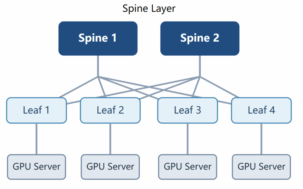
Each Leaf switch provides high-speed connectivity to GPU servers through Ethernet interfaces such as 100G, 200G, 400G, or 800G.
The Spine layer provides high-capacity interconnection between Leaf switches, enabling RDMA traffic to move between server groups.
A typical end-to-end data path follows:
GPU Server A → RoCE NIC → Leaf Switch A → Spine Switch → Leaf Switch B → RoCE NIC → GPU Server B
Every RoCE-capable forwarding point along this path must apply compatible traffic classification, queue management, and congestion-control policies.
Why End-to-End Coordination Matters
Lossless behavior cannot be achieved by enabling PFC on a single switch.
A properly designed RoCE network requires:
- Consistent traffic classification across NICs and switches.
- Correct priority-to-queue mappings on each forwarding device.
- Appropriate buffer allocation for burst absorption.
- ECN marking and supported endpoint congestion response.
- PFC configuration where required by the lossless design.
- Sufficient fabric bandwidth and traffic distribution across paths.
For high-performance GPU training, balanced or non-blocking Spine-Leaf designs can help limit persistent oversubscription, while ECMP and appropriate flow distribution improve path utilization.
Key takeaway: The goal is not simply to deploy high-speed RoCE switches, but to create a coordinated RDMA fabric from the transmitting NIC to the receiving NIC.
AI Server RoCE NIC: Traffic Classification
The foundation of an end-to-end lossless network begins at the server network interface card.
A RoCE NIC is responsible for generating RDMA traffic, applying traffic-class information, and implementing supported congestion-control behavior.
Separating RDMA Traffic from Regular Ethernet Traffic
Modern AI servers may generate several types of traffic simultaneously, including:
- RDMA data traffic for GPU communication.
- TCP/IP traffic for management and application services.
- Storage traffic.
- Congestion-control notification packets.
These traffic types may have different requirements for latency, throughput, and packet-loss tolerance.
A RoCE network therefore uses Quality of Service (QoS) classification to map traffic into appropriate switch priorities and hardware queues.
Two commonly used classification mechanisms are:
DSCP (Differentiated Services Code Point): A Layer 3 field in the IP header used to identify traffic classes across routed networks.
PCP (Priority Code Point): A three-bit priority field in an IEEE 802.1Q VLAN tag, commonly used for Layer 2 traffic prioritization.
Example Traffic Classification Policy
| Traffic Type | Example DSCP | Example Priority | Recommended Treatment |
| RoCE RDMA data | 24 | 3 | Dedicated lossless-capable class |
| Congestion Notification Packets (CNP) | 48 | 6 | High-priority control traffic |
| Regular TCP/IP | 0 | 0 | Best-effort or separately managed class |
These values illustrate one vendor-documented QoS design. They are not universal RoCE requirements and must be matched to the deployed NICs, switches, and QoS policies.
Why Consistent Classification Is Critical
Consider a GPU server transmitting RoCE traffic with DSCP 24.
The connected Leaf switch must correctly map that value to the intended RDMA queue. When the packet travels through a Spine switch and reaches another Leaf switch, the same QoS treatment must remain consistent.
If one switch maps the RDMA traffic into a best-effort queue, the packet may no longer receive the intended buffering, congestion marking, or flow-control behavior.
Therefore, end-to-end QoS consistency is a prerequisite for predictable RoCE network performance.
Switch Lossless Forwarding: PFC, Buffer Isolation, XOFF/XON, and Headroom
After RDMA packets enter the switch fabric, the forwarding hardware must absorb bursts and handle temporary congestion without allowing buffers to overflow unnecessarily.
This is where Priority Flow Control, buffer management, and headroom allocation become essential.
Priority Flow Control (PFC)
PFC, defined by IEEE 802.1Qbb, enables a switch to pause traffic on selected Ethernet priorities instead of stopping all traffic on a link.
Unlike traditional Ethernet PAUSE, which affects the entire link, PFC provides finer-grained flow control.
For example, if RDMA traffic uses priority 3, the switch can pause that priority while allowing other priorities to continue, subject to available resources and scheduling.
How PFC Works
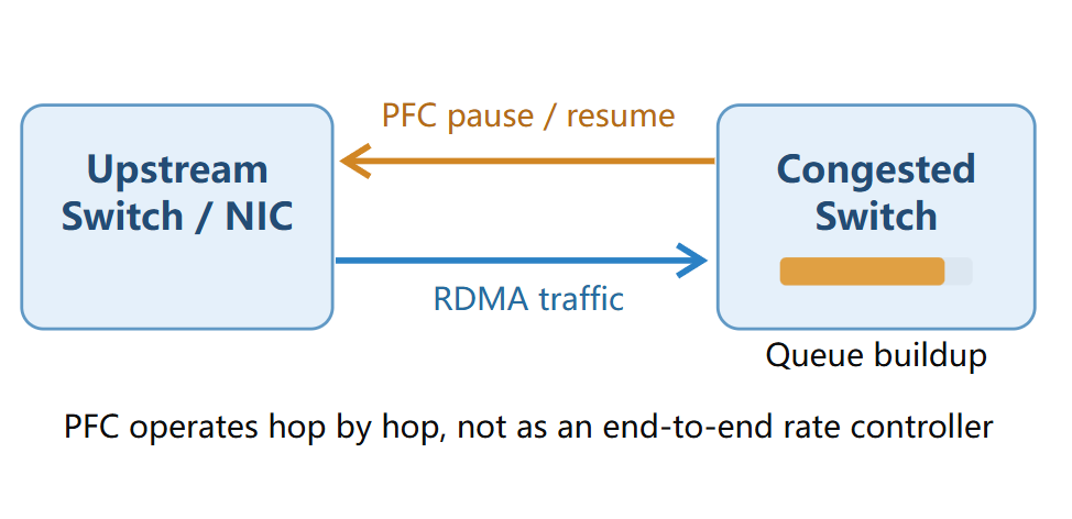
The basic sequence is:
- RDMA traffic enters a switch queue or priority group.
- Buffer occupancy increases as congestion develops.
- When a configured threshold is reached, the switch sends a PFC pause frame to its directly connected upstream neighbor.
- The upstream device temporarily stops transmitting traffic on the indicated priority.
- When buffer occupancy has sufficiently decreased, transmission can resume.
Because PFC operates between adjacent Ethernet devices, it does not directly regulate the original RDMA sender across an entire multi-hop fabric.
XOFF and XON Thresholds
Two concepts are commonly used to describe PFC buffer-control behavior:
XOFF Threshold: The buffer occupancy level at which a switch triggers PFC to pause traffic on the affected priority.
XON Threshold: The lower occupancy level at which the switch allows paused traffic to resume, commonly by transmitting a zero-quanta PFC frame or through expiration of the pause timer.
The difference between these thresholds provides hysteresis, helping prevent rapid oscillation between pause and resume states.
Correct threshold configuration is essential.
If XOFF is triggered too late, packets already in flight may exhaust the remaining buffer space. If it is triggered too early, the network may experience unnecessary pauses and reduced utilization.
Buffer Isolation and Shared Buffer Management
RoCE switches commonly use configurable buffer pools, priority groups, and traffic-class queues to manage different traffic types.
For example, the network may allocate:
- A lossless-capable buffer pool for RDMA traffic.
- Separate lossy or best-effort resources for conventional Ethernet traffic.
- Appropriate queue scheduling for congestion-control packets.
Buffer isolation helps prevent unrelated traffic from consuming all the resources needed to support the RDMA class.
However, dedicated buffer space does not eliminate congestion. Excessive bursts or sustained oversubscription can still overwhelm available resources.
Why Headroom Matters
Headroom is additional buffer capacity reserved to absorb packets that continue arriving after a PFC pause request is triggered.
A PFC pause frame cannot stop upstream traffic instantaneously. Propagation delay, device processing time, and data already in flight must all be considered.
A simplified engineering model is:
H_min ≈ R × T_response + H_margin
Where:
- H_min = Minimum estimated headroom in bytes.
- R = Incoming traffic rate in bytes per second.
- T_response = Effective time before the upstream flow is stopped.
- H_margin = Additional allowance for packet size, bursts, and implementation-specific behavior.
Actual headroom sizing depends on the switch architecture, cable distance, link speed, traffic patterns, and vendor-specific buffering model.
At 400G or 800G, even very short reaction delays can translate into significant amounts of data in flight.
Limitations of PFC
Although PFC helps protect RDMA traffic against packet loss, excessive use can introduce performance problems, including pause propagation, head-of-line blocking, and possible deadlock under unfavorable conditions.
Therefore, a robust RoCE architecture should use PFC as a protective mechanism rather than its primary approach to controlling persistent congestion.
The preferred engineering objective is to minimize unnecessary PFC activation through effective end-to-end congestion control.
Congestion Detection: ECN and DCQCN
PFC protects against buffer overflow by temporarily stopping traffic on a specific priority. However, repeatedly pausing traffic can increase latency and reduce network efficiency.
To manage congestion more effectively, RoCE networks commonly combine Explicit Congestion Notification (ECN) with Data Center Quantized Congestion Notification (DCQCN).
Together, these mechanisms allow the network to provide congestion feedback and enable the transmitting RDMA NIC to adjust its sending rate.
How ECN Detects Congestion
ECN is an IP-layer mechanism that signals congestion without necessarily dropping packets.
An ECN-capable RoCE switch monitors queue occupancy or other supported congestion metrics. When congestion exceeds configured marking thresholds, the switch can mark eligible packets with the ECN Congestion Experienced (CE) codepoint.
Instead of immediately discarding packets, the switch forwards the marked packets toward their destination, provided adequate buffer space remains.
This gives the endpoint an opportunity to react to congestion before it develops into severe queue buildup or packet loss.
How DCQCN Controls the Sending Rate
DCQCN is a congestion-control algorithm commonly implemented in RDMA-capable NICs.
It uses feedback from congestion-aware switches and receiving NICs to regulate the transmitting NIC’s sending rate.
A simplified DCQCN feedback loop includes three functional roles:
- Congestion Point (CP): A switch detecting congestion and marking eligible RoCEv2 packets with ECN.
- Notification Point (NP): The receiving RoCE NIC that detects ECN-marked traffic and generates Congestion Notification Packets (CNPs).
- Reaction Point (RP): The transmitting RoCE NIC that adjusts its injection rate after receiving CNP feedback.
ECN + DCQCN Workflow
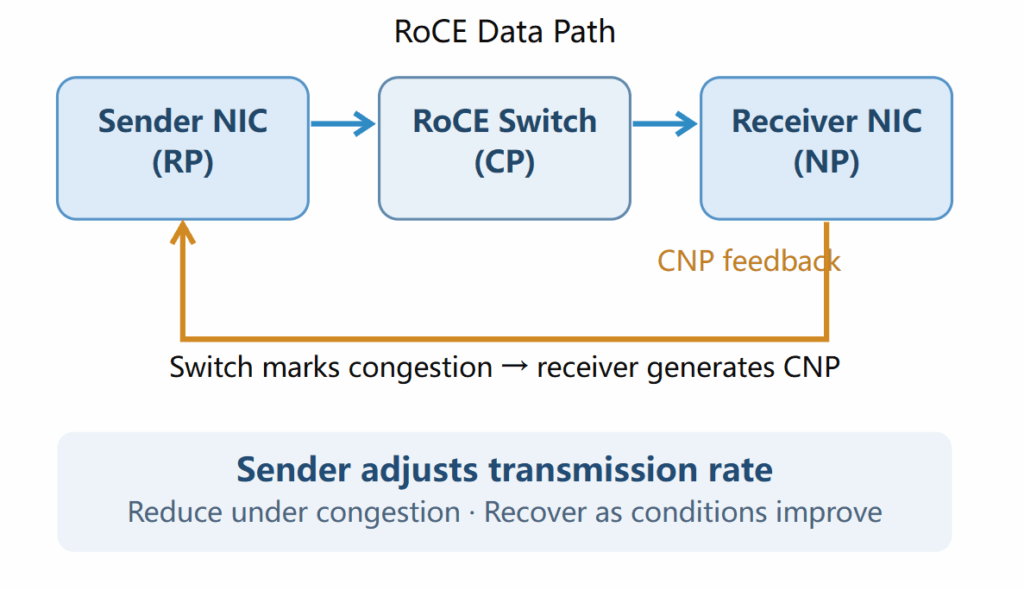
The congestion-control process works as follows:
Step 1: Traffic enters the network. The transmitting NIC sends RoCEv2 traffic toward the destination server through the Spine-Leaf fabric.
Step 2: Congestion develops. A switch detects increasing queue occupancy caused by competing flows or temporary traffic bursts.
Step 3: ECN marks packets. The switch marks eligible packets with the CE codepoint according to its configured ECN policy.
Step 4: The receiver generates CNP feedback. The receiving NIC recognizes congestion-marked packets and sends a CNP to the transmitting NIC.
Step 5: The sender adjusts its rate. The transmitting NIC uses its DCQCN algorithm to reduce its sending rate and then recover transmission capacity as congestion subsides.
The objective is to reduce queue buildup while maintaining high throughput and avoiding repeated PFC activation.
Why ECN and PFC Work Together
ECN and PFC address different stages of congestion.
| Mechanism | PFC | ECN + DCQCN |
| Primary purpose | Protect buffers from overflow | Regulate congestion at the source |
| Operating scope | Hop-by-hop Ethernet link | End-to-end congestion feedback |
| Trigger | PFC buffer thresholds | ECN congestion-marking policy |
| Response | Pause selected priority | Adjust RDMA sending rate |
| Main benefit | Reduce congestion-related packet drops | Reduce persistent congestion and queue buildup |
| Main limitation | Pause propagation and blocking | Feedback delay and tuning complexity |
In a well-tuned RoCE network, ECN-based congestion control should typically act before congestion becomes severe enough to require sustained PFC intervention.
The ECN marking policy must therefore be coordinated with buffer allocation, PFC thresholds, and NIC rate-control parameters.
Simply enabling PFC and ECN independently does not guarantee the intended behavior.
RTT-Based Proactive Congestion Control
Traditional DCQCN primarily relies on congestion signals generated after a switch detects queue buildup.
For large-scale AI fabrics, bursty collective communication can cause congestion conditions to change rapidly. Depending on traffic patterns and configuration, ECN feedback may arrive after queues have already grown substantially.
RTT-based congestion control (RTT-CC) provides another way to detect emerging congestion by measuring changes in packet round-trip time.
How RTT-Based Congestion Detection Works
Round-trip time represents the time required for a measurement or exchange to travel from a sender to a receiver and back.
In a relatively stable data center network, increases in measured RTT may indicate additional network queuing or other sources of delay.
An RTT-based controller can estimate a baseline delay and monitor deviations from that baseline.
Conceptually:
ΔRTT = RTT(measured) − RTT(baseline)
A sustained increase in ΔRTT may indicate developing congestion, allowing a supported NIC algorithm to adjust its transmission rate.
The exact response depends on the algorithm, including its measurement method, filtering logic, thresholds, and rate-adjustment policy.
Proactive vs. Reactive Congestion Control
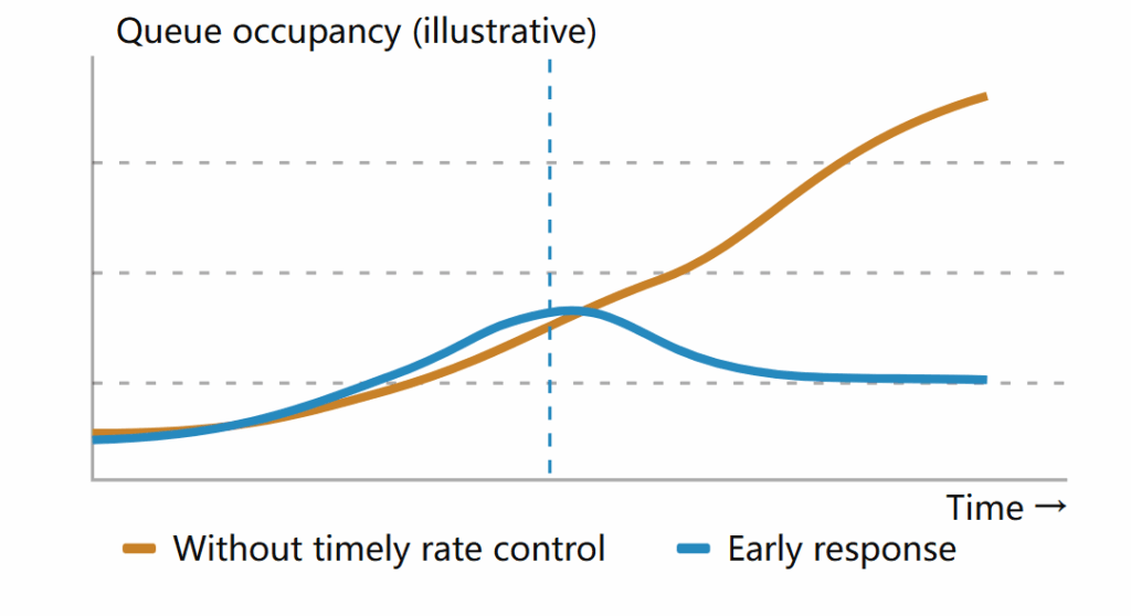
Traditional ECN-based DCQCN and RTT-based algorithms use different sources of congestion information.
ECN/DCQCN:
- Depends on congestion signals marked by ECN-enabled switches.
- Uses receiver-generated CNP feedback.
- Adjusts the sender’s rate based on the congestion-control algorithm.
- Requires coordinated switch marking and endpoint configuration.
RTT-Based Congestion Control:
- Uses latency measurements to detect changes in network conditions.
- Can identify queue growth through increasing measured delay.
- May reduce reliance on switch-generated ECN feedback, depending on implementation.
- Requires compatible endpoint hardware, firmware, and congestion-control support.
RTT measurements are not perfectly equivalent to queue occupancy. They can also be influenced by route changes, reverse-path behavior, and measurement noise. Consequently, reliable RTT-based control requires suitable filtering and calibration.
RTT-Based Congestion Control in Modern RoCE Fabrics
For example, NVIDIA documents a hardware-assisted RTT-based congestion-control mechanism called ZTR-RTT CC.
This implementation uses timestamped RTT measurements to make rate-control decisions and can operate without specialized switch-side ECN configuration. Its availability depends on supported hardware, firmware, and successful endpoint negotiation.
NVIDIA also documents deployments in which supported endpoints can negotiate DCQCN and ZTR-RTT CC capabilities. This does not mean that every RoCE NIC or switch automatically supports both mechanisms.
Why RTT-Based Control Matters for GPU Training
Distributed GPU workloads generate complex communication patterns, including All-Reduce, All-to-All, and other collective operations.
These workloads can create rapid bandwidth demand changes as many GPUs begin sending data simultaneously.
Under appropriate conditions, RTT-based congestion control can help:
- Detect increasing network delay before severe congestion develops.
- Respond more quickly to emerging traffic contention.
- Reduce sustained queue buildup.
- Limit unnecessary PFC pauses.
- Support more predictable communication latency.
However, RTT-based congestion control does not independently guarantee lossless forwarding or eliminate the need for appropriate fabric capacity, traffic engineering, and endpoint compatibility.
For AI clusters, the best congestion-control strategy depends on the switch architecture, NIC capabilities, software stack, and actual communication workload.
FAQ: RoCE Switches and Lossless RDMA Networks
What is a RoCE switch?
A RoCE switch is an Ethernet switch designed or configured to support RDMA over Converged Ethernet traffic. RoCE-capable switches typically provide high-speed forwarding, QoS classification, congestion-aware buffering, ECN marking, and optional PFC support. These features help deliver low-latency, low-loss communication for AI training, storage, and other RDMA workloads.
Does RoCE require a completely lossless network?
Not always. RoCE deployments have traditionally used lossless Ethernet mechanisms such as PFC to reduce packet loss. However, some modern RoCE NICs support enhanced packet-loss recovery and operation over lossy networks.
The appropriate design depends on the NIC capabilities, congestion-control implementation, application requirements, and acceptable performance characteristics.
What is the difference between PFC and ECN in RoCE?
PFC is a hop-by-hop flow-control mechanism that pauses selected Ethernet priorities when buffers approach configured thresholds. ECN marks congestion in eligible IP packets, allowing compatible endpoints to adjust their sending rates.
PFC focuses on protecting buffers against overflow, while ECN-based congestion control aims to prevent persistent queue buildup.
Why is DCQCN important for RDMA networking?
DCQCN enables RDMA NICs to respond to network congestion through ECN and CNP feedback. By dynamically adjusting transmission rates, it helps improve bandwidth utilization, reduce queue buildup, and limit unnecessary PFC activity.
Can 400G and 800G Ethernet switches support RoCE?
Yes, provided the switches offer the necessary forwarding, QoS, buffer-management, and congestion-control features for the intended RDMA deployment.
Port speed alone does not determine RoCE suitability. Network architects should also evaluate ECN capabilities, PFC support, buffer architecture, telemetry, latency, and compatibility with the deployed RDMA NICs.
Why is Spine-Leaf architecture suitable for AI cluster networking?
Spine-Leaf architecture provides scalable connectivity, predictable network hop counts, and multiple paths between GPU servers. With appropriate link capacity, path distribution, and congestion management, it can support high-throughput east-west RDMA communication in large AI clusters.
What is the difference between DCQCN and RTT-based congestion control?
DCQCN primarily uses ECN feedback from congested switches to regulate the transmitting NIC’s rate. RTT-based algorithms use measured communication delay as a congestion signal and may detect emerging queue growth without relying solely on switch ECN markings.
Both mechanisms aim to reduce congestion, but their implementation requirements, response behavior, and deployment compatibility differ.
Is enabling PFC enough to build a lossless RoCE network?
No. Enabling PFC alone does not provide complete end-to-end congestion management. A robust RoCE fabric also requires consistent traffic classification, adequate buffers and headroom, correct ECN and NIC congestion-control settings, appropriate bandwidth provisioning, and continuous monitoring.
Conclusion
Building an end-to-end lossless RDMA network requires more than high-bandwidth Ethernet switches.
A reliable RoCE fabric must coordinate congestion management across the entire communication path, beginning with traffic classification at the server NIC and continuing through every Leaf and Spine switch.
PFC provides hop-by-hop protection against buffer overflow. Buffer isolation and headroom help absorb transient bursts. ECN and DCQCN enable end-to-end congestion feedback and sender-rate adjustment, while RTT-based congestion control introduces latency-aware mechanisms that can improve congestion responsiveness in supported deployments.
For large-scale AI clusters, these technologies work alongside Spine-Leaf network design, high-speed Ethernet connectivity, and appropriate capacity planning to reduce packet loss, limit latency variation, and support more efficient GPU communication.
FiberMall provides high-speed optical interconnect solutions for 100G, 200G, 400G, and 800G data center networks, supporting the physical connectivity requirements of modern Spine-Leaf Ethernet fabrics and AI infrastructure.
By combining reliable optical connectivity with properly engineered RoCE switching and congestion-control mechanisms, organizations can build scalable RDMA networks capable of supporting increasingly demanding AI and high-performance computing workloads.
Related Products:
-
 NVIDIA MMS4X00-NM-T Compatible 800GBASE 2 x DR4/DR8 OSFP IHS/Closed Finned Top PAM4 1310nm 500m DOM Dual MTP/MPO-12 SMF Optical Transceiver Module
$600.00
-
NVIDIA MMS4X00-NM16 Compatible OSFP 8x100G DR PAM4 1310nm MPO-16 500m SMF DDM Optical Transceiver Module
$800.00
-
NVIDIA MMS4C11 (980-9IAU1-00XM01) Compatible 1.6T 2 x DR4/DR8 OSFP224 PAM4 1311nm 500m IHS/Finned Top Dual MPO-12 SMF Optical Transceiver Module
$1500.00
-
NVIDIA MMS4C11 (980-9IAU1-00XM00) Compatible 1.6T 2 x DR4/DR8 OSFP224 PAM4 1311nm 500m RHS/Flat Top Dual MPO-12 SMF Optical Transceiver Module
$1500.00