

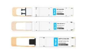
What will Happen if I Plug in 100G QSFP Transceivers that Consume Greater than 3.5W?

Picture of Harry Collins

Harry Collins

Answered on 6:18 am

It depends on the type and model of the device that you are using to plug in the 100G QSFP transceivers. Different devices may have different power budgets and limitations for their QSFP ports. You should always check the device specifications and compatibility matrix before plugging in any transceiver module.

Some possible scenarios that may happen if you plug in 100G QSFP transceivers that consume greater than 3.5W are:

  • The device may not recognize or support the transceiver module, and display an error message or warning.
  • The device may recognize and support the transceiver module, but limit its performance or functionality due to insufficient power supply.
  • The device may overheat or damage its components due to excessive power consumption by the transceiver module.

People Also Ask

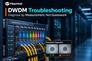
DWDM Troubleshooting: Diagnose by Measurement, Not Guesswork

A link runs clean for two years. Then one Tuesday, two edge channels start throwing errors while the other thirty-eight remain healthy. The amplifier raises an alarm, so someone replaces it. The errors return a week later because the amplifier was never the problem. That sequence is common enough to

400G per Lane: The Next Optical Signaling Generation, Explained

400G per lane refers to a nominal data rate of 400 gigabits per second (Gb/s) carried by a single electrical lane or optical data channel, depending on the interface being discussed. It represents the next step beyond the 200G-per-lane signaling used in 1.6T-class modules. For electrical interfaces, the industry often

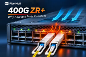
400G ZR+ Coherent Transceivers: Why They Overheat Adjacent Ports — and How to Fix It

400G ZR+ coherent transceivers are changing how operators build high-capacity optical networks. By integrating coherent signal processing into compact QSFP-DD and OSFP modules, they enable long-distance 400G connectivity directly from compatible switches and routers, reducing dependence on separate optical transport equipment. But this integration creates a thermal challenge. A conventional

USFP Connector Explained: The 2D Array and Two-Step Insertion

The USFP connector is the electrical interface that connects a USFP optical module to the host system in a switch or SuperNIC. It uses a two-dimensional (2D) array connector with a two-step insertion design, in which high-speed contacts engage after the module is inserted. The biggest challenge in scaling pluggable

NVIDIA H200 Burn-In Test and Maintenance: A Complete Delivery Checklist

An H200 burn-in test is essential for validating GPU stability, memory integrity, interconnect performance, and cooling behavior before an NVIDIA H200 server enters production. The NVIDIA H200 Tensor Core GPU features 141 GB of HBM3e memory and up to 4.8 TB/s of memory bandwidth. H200 SXM configurations support up to

ROADM Architecture: Degrees, CDC, and WSS Explained

A 20-degree ROADM site can consume three equipment cabinets, more than a hundred circuit boards, and around 400 fibers inside the building. The wavelengths move in software. The hardware does not. In one engineering example documented by ZTE, a node of this scale requires substantial cabinet space, board capacity, and

Related Articles

800g sr8 and 400g sr4

800G SR8 and 400G SR4 Optical Transceiver Modules Compatibility and Interconnection Test Report

Version Change Log Writer V0 Sample Test Cassie Test Purpose Test Objects:800G OSFP SR8/400G OSFP SR4/400G Q112 SR4. By conducting corresponding tests, the test parameters meet the relevant industry standards, and the test modules can be normally used for Nvidia (Mellanox) MQM9790 switch, Nvidia (Mellanox) ConnectX-7 network card and Nvidia (Mellanox) BlueField-3, laying a foundation for
Read More »
DWDM troubleshooting

DWDM Troubleshooting: Diagnose by Measurement, Not Guesswork

A link runs clean for two years. Then one Tuesday, two edge channels start throwing errors while the other thirty-eight remain healthy. The amplifier raises an alarm, so someone replaces it. The errors return a week later because the amplifier was never the problem. That sequence is common enough to

Read More »
400G per lane

400G per Lane: The Next Optical Signaling Generation, Explained

400G per lane refers to a nominal data rate of 400 gigabits per second (Gb/s) carried by a single electrical lane or optical data channel, depending on the interface being discussed. It represents the next step beyond the 200G-per-lane signaling used in 1.6T-class modules. For electrical interfaces, the industry often
Read More »
400G ZR+

400G ZR+ Coherent Transceivers: Why They Overheat Adjacent Ports — and How to Fix It

400G ZR+ coherent transceivers are changing how operators build high-capacity optical networks. By integrating coherent signal processing into compact QSFP-DD and OSFP modules, they enable long-distance 400G connectivity directly from compatible switches and routers, reducing dependence on separate optical transport equipment. But this integration creates a thermal challenge. A conventional

Read More »
USFP Connector

USFP Connector Explained: The 2D Array and Two-Step Insertion

The USFP connector is the electrical interface that connects a USFP optical module to the host system in a switch or SuperNIC. It uses a two-dimensional (2D) array connector with a two-step insertion design, in which high-speed contacts engage after the module is inserted. The biggest challenge in scaling pluggable

Read More »
ROADM

ROADM Architecture: Degrees, CDC, and WSS Explained

A 20-degree ROADM site can consume three equipment cabinets, more than a hundred circuit boards, and around 400 fibers inside the building. The wavelengths move in software. The hardware does not. In one engineering example documented by ZTE, a node of this scale requires substantial cabinet space, board capacity, and

Read More »
Scroll to Top