A hyperscale data center recently faced a crisis. The facility needed to connect 10000 new servers to the network, but only 40 percent of the planned fiber pathway capacity remained operational. The existing ceiling structure prevented operators from installing extra cable trays. The solution required not additional space but MPO connectors. The team used a single connector that consolidated 24 fibers into a smaller-than-thumb-size connector to connect the entire deployment without needing to access the pathways. Installation time decreased by 80 percent.
This is the power of Multi-fiber Push-On connectivity.
Data centers are currently transitioning from 100G to 400G and 800G, which has established MPO connectors as the standard interface for high-speed parallel optical systems. Network engineers need to master MPO technology.
This guide contains all necessary information about MPO fiber connector systems, including technical specifications, polarity methods with decision frameworks, guidance for selecting cable types, and procedures to clean and maintain the equipment. It provides essential knowledge for both new projects and troubleshooting existing systems.
FiberMall provides data centers around the globe with MPO connectivity solutions. Our engineering teams managed MPO deployments that range from 40G to 800G. The guide presents our acquired technical standards together with our field experience, which we collected through our work with network engineers and data center architects.

What Is an MPO Connector?
The MPO connector is a high-density fiber optic connector that terminates multiple fibers in a single precision-molded MT ferrule made of glass-filled polymer. Its space-saving rectangular design allows connections of 8 to 72 fibers, far exceeding traditional LC and SC connectors that support only 1 or 2 fibers.
The connector follows international standards IEC 61754-7 and TIA-604-5 (FOCIS 5), ensuring interoperability between manufacturers. This standardization makes MPO the backbone of modern high-density fiber infrastructure.
Key Technical Specifications
| Specification | Details |
| Fiber Capacity | 8, 12, 16, 24, 32, 48, or 72 fibers |
| Common Types | MPO-8, MPO-12, MPO-16, MPO-24 |
| Ferrule Material | Precision-molded ceramic MT ferrule |
| Connector Gender | Male (with guide pins) and Female (with pin holes) |
| Polish Types | UPC (Ultra Physical Contact) and APC (Angled Physical Contact) |
| Insertion Loss | ≤0.20–0.75 dB depending on grade |
| Operating Temperature | -40°C to +85°C |
Connector Components
Ferrule: The MT (Mechanical Transfer) ferrule, manufactured through precision molding, holds multiple fibers in a straight line. The standard MPO-12 ferrule arranges 12 fibers in a single row with precise spacing.
Guide Pins: Male connectors feature two metal alignment pins that extend from the front of the ferrule. Female connectors have matching holes. These pins ensure accurate fiber alignment during mating, which is essential for optical performance.
Keying Mechanism: The housing contains a raised plastic component that allows users to insert the device correctly while preventing them from making wrong insertions. The fiber mapping and polarity of the device depend on the user selecting either the “key up” or “key down” position.
White Dot Indicator: A marking on the connector body denotes fiber position #1, which is vital for managing polarity and solving problems.
For additional technical details on MPO fiber infrastructure, see our MPO connector type guide.

MPO vs MTP: Understanding the Difference
MPO and MTP are often used interchangeably, but important distinctions exist. Understanding these differences helps you choose the right connector for your specific performance requirements and budget.
The Core Difference
MPO (Multi-fiber Push-On): The generic industry standard defined by IEC 61754-7. Any manufacturer can produce MPO connectors meeting these specifications.
MTP (Multi-fiber Termination Push-on): A trademarked enhanced version manufactured exclusively by US Conec. MTP connectors exceed standard MPO specifications with tighter tolerances and additional features.
Key Point: All MTP connectors function as MPO connectors, but not all MPO connectors meet MTP performance requirements.
Side-by-Side Performance Comparison
| Feature | Standard MPO | MTP (Enhanced) |
| Insertion Loss | 0.35–0.75 dB typical | 0.15–0.35 dB typical |
| Elite Grade Loss | Not available | <0.20 dB |
| Durability | ~500 mating cycles | ~600+ mating cycles |
| Guide Pins | Standard metal | Elliptical stainless steel |
| Ferrule Design | Fixed | Floating ferrule |
| Pin Clamp | Plastic | Metal |
| Housing | Fixed molded | Removable for cleaning |
| Spring Design | Standard round | Elliptical for ribbon clearance |
When to Choose Standard MPO
Standard MPO connectors make sense for:
- Cost-sensitive deployments where budget constraints matter
- Enterprise networks with moderate density requirements
- Applications with relaxed insertion loss budgets
- Installations where the connector mating cycles remain low
- MDF to IDF connections and campus backbones
When to Choose MTP
MTP connectors are worth the premium for:
- Hyperscale data centers with strict loss budgets
- High-speed parallel optics (100G, 400G, 800G)
- Environments requiring frequent reconfiguration
- Links where every decibel of loss matters
- Long-term infrastructure where reliability is paramount
The decision ultimately depends on your link budget calculations. In a complex data center fabric with multiple patch points, premium MTP connectors preserve signal strength and reduce troubleshooting.
Learn more about MPO vs MTP, see our MPO vs MTP comparison guide.
MPO Connector Types and Configurations
MPO connectors come in several configurations. Selecting the right type ensures compatibility with your transceivers, switches, and cabling infrastructure.
Fiber Count Variants
| Type | Fiber Count | Typical Applications |
| MPO-8 | 8 fibers | 40G/100G SR4, 200G, 400G breakout |
| MPO-12 | 12 fibers | Universal data center, 40G/100G/400G |
| MPO-16 | 16 fibers | 400G SR8, 800G SR8 applications |
| MPO-24 | 24 fibers | High-density aggregation, 100G SR10 |
| MPO-32+ | 32-72 fibers | Hyperscale, specialized applications |
MPO-8: Uses 8 fibers (4 transmit, 4 receive) for 40G/100G SR4 applications. The 8-fiber configuration uses outer positions on a 12-fiber ferrule, leaving middle fibers unused.
MPO-12: The most versatile configuration supporting multiple applications. Standard for 40G/100G SR4 and widely used for trunk cabling. The extra 4 fibers (positions 5-8 in a 12-fiber layout) remain unused for SR4 but enable migration flexibility.
MPO-16: Emerging as the standard for 400G SR8 and 800G SR8 applications. Native 16 fibers (8 Tx, 8 Rx) at 50G or 100G per lane. This configuration eliminates wasted fibers compared to using MPO-24 for 8-lane applications.
MPO-24: Two rows of 12 fibers providing maximum density. Supports 100G SR10 (10 lanes), 120G applications, or three simultaneous 40G links. High-density trunk cables frequently use this method to maintain future adaptability.

Gender and Keying
Male Connectors: Feature two guide pins that extend from the ferrule face. Used primarily for cable-to-cable connections and trunk extensions.
Female Connectors: Feature two holes that allow the reception of guide pins. Required for connecting to equipment ports, transceivers, and cassettes.
Critical Rule: Equipment ports that include switches and transceivers function as male connectors. Cables that connect directly to equipment must use female connectors.
Key Orientation:
- Key Up: Key positioned at the top when viewing the connector face
- Key Down: Key positioned at the bottom
Key orientation affects fiber mapping and must be consistent within your polarity scheme. Click here to learn more about MPO polarity.
Polish Types
UPC (Ultra Physical Contact): Slightly curved 0° polish used for multimode fiber (OM3/OM4/OM5). Standard for 40G/100G/400G SR applications.
APC (Angled Physical Contact): 8° angled polish required for single-mode fiber. Minimizes back-reflection to ≥60 dB. Essential for 400G/800G DR/FR/LR applications over single-mode.
Compatibility Warning: Never mix APC and UPC connectors. The angled ferrule of APC will damage UPC connectors and create high loss.
For high-speed transceiver connections, MPO connectors interface directly with OSFP transceivers for 800G applications.
MPO Polarity Methods Explained
The system establishes correct connections between transmit (Tx) fibers and receive (Rx) fibers through polarity management. The most frequent problem with MPO deployment happens when operators establish incorrect polarity because it prevents link activation.
MPO systems use three standardized polarity methods defined by TIA-568.3-D. The way each method functions needs to show proper installation procedures because it helps avoid expensive installation mistakes.
Type A Polarity — Straight-Through
Configuration: Fiber position 1 connects to 1, 2 to 2, through 12 to 12. No fiber crossing occurs.
Adapter Orientation: Key-up to key-down flips the connector, maintaining straight-through mapping.
Best Applications:
- Modular MPO cassette deployments
- Migration systems (10G → 40G → 100G)
- Simple point-to-point links
- Environments requiring maximum flexibility
Advantages: Simplest trunk manufacturing, widely supported, easiest for long-term infrastructure evolution.
Type B Polarity — Reversed/Flipped
Configuration: Fiber position 1 connects to 12, 2 connects to 11, completely reversing the fiber array.
Adapter Orientation: Key-up to key-up (no flip) with the reversed mapping ensuring Tx connects to Rx.
Best Applications:
- Direct parallel optic connections (40G/100G/400G/800G SR/DR)
- Spine-leaf data center fabrics
- High-speed transceiver-to-transceiver links
- Standard for modern data center deployment
Critical Importance: Type B polarity is essential for parallel optics. QSFP+/QSFP28/QSFP-DD/OSFP transceivers expect this polarity. Using Type A for parallel optics results in Tx-to-Tx connections that won’t link.

Type C Polarity — Pairwise Swapped
Configuration: Adjacent fiber pairs swap positions (1↔2, 3↔4, 5↔6, etc.).
Adapter Orientation: Key-up to key-down with pairwise swapping.
Best Applications:
- MPO-to-LC duplex breakout systems
- Specific legacy duplex applications
- Rarely used for modern parallel optics
Polarity Selection Matrix
| Application | Recommended Polarity | Rationale |
| 40G SR4 | Type B | Standard parallel optic requirement |
| 100G SR4 | Type B | Standard parallel optic requirement |
| 200G SR4 | Type B | Standard parallel optic requirement |
| 400G SR8 | Type B | Standard parallel optic requirement |
| 400G DR4 | Type B | Standard parallel optic requirement |
| 800G SR8 | Type B | Standard parallel optic requirement |
| Cassette-based migration | Type A | Flexibility for speed changes |
| MPO-LC breakout | Type C or A | Depends on patch cable polarity |
During the hyperscale deployment, senior network engineer Marcus Chen described his polarity challenge: “The team installed 500 MPO trunks using Type A polarity, but later discovered that our 100G SR4 transceivers required Type B. The complete installation required reconfiguration. Now we standardize on Type B for all parallel optic applications and document everything meticulously.”
Best Practices
Golden Rule: Choose one polarity method and enforce it across your entire site. Mixing A, B, and C creates chaos and link failures.
Documentation: Label every cable end with polarity type, fiber count, and direction. Future maintenance depends on clear documentation.
Testing: Always verify polarity with a light source or OLTS before declaring links complete. Don’t assume—verify.
MPO Cable Types and Applications
MPO cables come in several types designed for specific deployment scenarios. Understanding these differences ensures you select the right cable for your architecture.
Trunk Cables
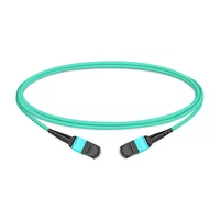
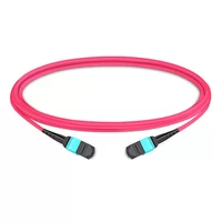
Description: Multi-fiber cables with MPO connectors on both ends. Available in 8, 12, 16, 24, or 48 fiber configurations.
Applications:
- Backbone connections between distribution areas
- Main distribution frame (MDF) to intermediate distribution frame (IDF) links
- Inter-row connections in data centers
- Campus backbone cabling
Advantages:
- High fiber count in single cable reduces pathway congestion
- Pre-terminated for rapid deployment
- Factory-polished for consistent quality
Specifications to Consider:
- Plenum vs. LSZH jacket ratings
- Single-mode (OS2) vs. multimode (OM4/OM5)
- Pulling eye options for installation
Breakout/Fanout Cables
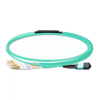
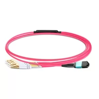
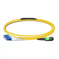
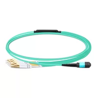
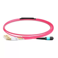
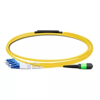
Description: MPO connector on one end, fanning out to individual connectors (typically LC duplex) on the other.
Common Configurations:
- MPO-8 to 4×LC duplex (for 40G to 4×10G)
- MPO-12 to 6×LC duplex (for 100G to 6×10G or 3×40G)
- MPO-24 to 12×LC duplex (high-density server connections)
Applications:
- Connecting high-speed switch ports to lower-speed servers
- Breaking out 100G to 25G server connections
- Transitioning from MPO infrastructure to LC-based equipment
Key Consideration: Breakout cable polarity must match your infrastructure polarity (typically Type B).

Harness Cables
Description: Short MPO-to-MPO cables for equipment interconnection within racks.
Applications:
- Switch-to-switch connections in spine-leaf topologies
- Equipment interconnection within the same rack
- Patch field connections
Length: Typically 1-5 meters, optimized for rack-level connectivity.
Data Center Architecture Applications
Spine-Leaf Topology:
MPO trunk cables create the spine layer that links leaf switches between different racks. MPO-24 trunks serve to connect multiple spine links using 100G and 400G bandwidth between network points.
Top-of-Rack (ToR) Deployment:
MPO harness cables connect ToR switches to spine switches. The short lengths of 1-3m cables create fewer cable congestion problems.
End-of-Row (EoR) Deployment:
MPO trunks extend from EoR switches to patch panels in server racks and split into LC connections for each server.
Migration Strategy:
MPO infrastructure enables speed upgrades without recabling. The same MPO-12 trunk that carries 40G today can support 100G, 400G, or 800G with transceiver upgrades.
MPO for High-Speed Transceivers
MPO connectors serve as the physical interface for parallel optical transceivers from 40G through 800G and beyond. Understanding these connections helps you design scalable infrastructure.
40G Applications
40GBASE-SR4: Uses 8 fibers (4 Tx, 4 Rx) at 10 Gbps per lane. Connects via MPO-8 or MPO-12 (using outer 8 positions).
Deployment Notes: MPO-12 infrastructure supports 40G SR4 while preserving 4 spare fibers for future use.
100G Applications
100GBASE-SR4: 8 fibers at 25 Gbps per lane. MPO-8 or MPO-12 compatible.
100GBASE-SR10: 20 fibers at 10 Gbps per lane. Requires MPO-24 configuration.
100GBASE-DR4: Single-mode 500m reach. Uses MPO-12 with APC polish.
400G Applications
400GBASE-SR8: 16 fibers at 50 Gbps per lane. Native MPO-16 connector or dual MPO-12 (8 fibers each).
400GBASE-DR4: 8 fibers at 100 Gbps per lane. Single-mode with MPO-12 APC.
400GBASE-SR16: 16 fibers at 25 Gbps per lane. MPO-16 configuration.
Critical Decision: For new 400G deployments, specify MPO-16 rather than dual MPO-12. MPO-16 eliminates the 4-fiber waste of using MPO-12 for 8-lane applications.
800G Applications
800GBASE-SR8: 16 fibers at 100 Gbps per lane. Requires MPO-16 configuration.
800GBASE-DR8: 16 fibers at 100 Gbps per lane over single-mode. MPO-16 APC.
Infrastructure Impact: 800G switches require MPO-16 ports or MPO-24 with lane aggregation. Plan new installations with MPO-16 or MPO-24 to support 800G migration.
1.6T and Beyond
Emerging 1.6T standards will use 16 fibers at 200 Gbps per lane or 32 fibers at 100 Gbps per lane. MPO-24 and emerging MPO-32 configurations will support these speeds.
Strategic Implication: Installing MPO-24 infrastructure today provides a path to 1.6T without recabling.
OSFP and MPO Integration
OSFP (Octal Small Form-factor Pluggable) transceivers for 800G and 1.6T applications use MPO connectors as their standard interface:
- 800G OSFP: MPO-16 configuration
- 1.6T OSFP: MPO-16 (200G/lane) or MPO-32 (100G/lane)
This connection between MPO infrastructure and next-generation transceivers makes MPO expertise essential for modern network architects.
For detailed information on OSFP transceivers and their MPO requirements, see our complete OSFP guide.
A major cloud provider recently deployed 800G OSFP switches, which operate through MPO-16 links. Their infrastructure team reported that they achieved 40% cabling reduction through their transition from a dual MPO-12 to a single MPO-16 system, which also eliminated one connection point per link.
MPO Cleaning and Maintenance
MPO connectors require proper cleaning and maintenance. With 12, 16, or 24 fibers in one connector, contamination affects multiple channels simultaneously.
Cleaning Procedures
Dry Cleaning (Recommended for 16+ fiber MPOs):
- Use cassette-style cleaners designed for MPO (Optipop or equivalent)
- For male connectors: Insert into cleaner with pins aligned to grooves
- Draw through slowly with consistent pressure
- Make two passes at slight angles
- Inspect before connecting
Wet Cleaning (For heavy contamination):
- Use isopropyl alcohol (99% purity) with lint-free wipes
- Apply minimal alcohol—saturated wipes that leave residue
- Clean in one direction, do not scrub
- Follow with dry cleaning to remove residue
- Allow complete drying before inspection
Tools Required:
- Optipop cassette cleaners (male and female versions)
- Fiber inspection microscope (200-400x magnification)
- Lint-free cleaning wipes
- Isopropyl alcohol (99%)
Inspection Standards
IEC 61300-3-35 defines cleanliness standards for fiber endfaces:
| Defect Type | Zone 1 (Core) | Zone 2 (Cladding) | Zone 3 (Adhesive) |
| Scratches | None >3μm | None >5μm | None >5μm |
| Particles | None >5μm | None >10μm | None >25μm |
| Liquid | None | None visible | None visible |
Inspection Procedure:
- Inspect before every connection
- Use a fiber microscope with an MPO adapter
- Check all fibers in the array
- Clean if any fiber exceeds standards
- Re-inspect after cleaning
Common Issues and Solutions
High Insertion Loss:
- Cause: Contamination on the endface
- Solution: Clean and re-inspect
Intermittent Connections:
- Cause: Damaged guide pins (male) or worn holes (female)
- Solution: Replace the connector or cable
Polarity Mismatches:
- Cause: Wrong polarity type for the application
- Solution: Verify with light source, replace if necessary
Gender Mismatches:
- Cause: Male-male or female-female attempt
- Solution: Use a gender changer adapter or replace cable
Preventive Maintenance
Monthly: Spot-check critical links with an inspection microscope
Quarterly: Clean all patch panel connections
Annually: Full infrastructure inspection and documentation update
Best Practices:
- Keep dust caps on unused connectors
- Clean before every mating
- Document cleaning procedures for your team
- Train technicians on proper technique
FAQ
What is the difference between MPO and MTP?
MPO is the generic industry standard for a basic interconnection system. MTP is a trademarked product developed by US Conec as an advanced connector design that provides better performance through improved durability, reduced insertion loss, and precise manufacturing specifications. MTP connectors comply with MPO standards, while not all MPO connectors fulfill MTP design requirements.
What polarity method should I apply to 100G SR4?
Use Type B polarity for all parallel optic applications, including 100G SR4. The Type B system uses a fiber array, which connects transmit fibers with receive fibers through the fiber array setup that connects fiber 1 to fiber 12 while fiber 2 connects to fiber 11. Type A will cause Tx-to-Tx connections that won’t link.
What steps should I follow to clean MPO connectors?
Use a cassette-style dry cleaner system. For male connectors, align pins to grooves and draw through slowly. Perform two passes at multiple angles. Inspect the fiber endface through a microscope before making a connection. For severe contamination, use minimal isopropyl alcohol followed by dry cleaning.
Can MPO-12 connect to MPO-24?
MPO-12 and MPO-24 connectors are not compatible because their ferrule sizes and pin distances differ. Use breakout cables or cassettes for fiber count transitions.
What is the purpose of using MPO-16?
MPO-16 provides native support for both 400G SR8 and 800G SR8 applications. It uses 16 fibers (8 transmitting and 8 receiving) and avoids the fiber waste that occurs when using MPO-12 for 8-lane applications. MPO-16 has become the standard deployment method for 800G systems.
Conclusion
MPO connectors have become essential infrastructure for modern data centers. These high-density connectors, which operate from 40G up to 800G and higher, deliver the necessary bandwidth for cloud computing, AI clusters, and hyperscale networks.
The key takeaways for your deployments:
- Standardize on Type B polarity for parallel optic applications—it’s the industry standard for 40G through 800G
- Choose fiber count based on roadmap—MPO-16 for 400G/800G, MPO-24 for maximum flexibility
- Match gender to application—female for equipment connections, male for trunk extensions
- Clean before every connection—contamination is the leading cause of MPO link failures
- Document everything—clear labeling prevents future troubleshooting headaches
Whether you’re upgrading existing infrastructure or building new facilities, MPO connectivity provides the density and scalability modern networks demand.
Ready to deploy MPO in your data center? Explore FiberMall’s MPO cable solutions or request a quote for your specific requirements. Our engineering team has supported MPO deployments worldwide and can help you design infrastructure that scales from 100G through 800G and beyond.
Related Products:
-
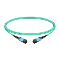
 1m (3ft) 12 Fibers Female to Female MPO Trunk Cable Polarity B LSZH OM3 50/125 Multimode Fiber
$20.00
1m (3ft) 12 Fibers Female to Female MPO Trunk Cable Polarity B LSZH OM3 50/125 Multimode Fiber
$20.00
-
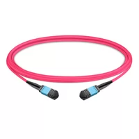
1m (3ft) 12 Fibers Female to Female MPO Trunk Cable Polarity B LSZH Multimode OM4 50/125
$21.00
-
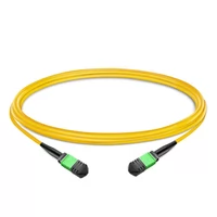
1m (3ft) 12 Fibers Female to Female MPO Trunk Cable Polarity B LSZH OS2 9/125 Single Mode
$26.00
-
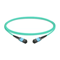
1m (3ft) 12 Fibers Low Insertion Loss Female to Female MPO Trunk Cable Polarity B LSZH OM3 50/125 Multimode Fiber
$32.00
-
1m (3ft) 12 Fibers Female to Female Elite MTP Trunk Cable Polarity B LSZH OM3 50/125 Multimode Fiber
$35.00
-
1m (3ft) 12 Fibers Female to Female Elite MTP Trunk Cable Polarity B LSZH Multimode OM4 50/125
$36.00
-
1m (3ft) MPO UPC Female to 4 LC UPC Duplex OM3 50/125 Multimode Fiber Breakout Cable, 8 Fibers, Type B, LSZH, Aqua
$20.00
-
1m (3ft) MPO UPC Female to 4 LC UPC Duplex OM4 50/125 Multimode Fiber Breakout Cable, 8 Fibers Type B, LSZH, Aqua/Violet
$23.00
-
1m (3ft) MPO APC Female to 4 LC UPC Duplex OS2 9/125 Single Mode Fiber Breakout Cable, 8 Fibers Type B, LSZH, Yellow
$24.00
-
1m (3ft) MTP Female to 4 LC UPC Duplex OM3 50/125 Multimode Fiber Breakout Cable, 8 Fibers, Type B, Elite, Plenum (OFNP), Aqua
$28.00
-
1m (3ft) MTP Female to 4 LC UPC Duplex OM4 50/125 Multimode Fiber Breakout Cable, 8 Fibers, Type B, Elite, Plenum (OFNP), Aqua/Violet
$30.00
-
1m (3ft) MTP APC Female to 4 LC UPC Duplex OS2 9/125 Single Mode Fiber Breakout Cable, 8 Fibers, Type B, Elite, Plenum (OFNP), Yellow
$32.00