
Consider an illustrative 640 km regional route between two carrier hotels. Rafael’s team needs a fourfold capacity increase, and a proposal promises that moving from 400G to 800G per wavelength will deliver it.
The optical modules may be capable of 800G, but the grid tells a different story. Under the proposed channel plan, the theoretical fiber capacity rises by only about one-third—not fourfold. The optics are not the problem; the spectrum allocation is.
That gap is where many coherent DWDM projects go wrong. Coherent detection enables 400G and 800G transmission on a single optical carrier. But total capacity does not scale with the number printed on the module. It depends on bits per hertz, which are governed by channel width, modulation, and the usable spectrum.
This guide covers coherent DWDM at the layer where decisions get made: how the technology works, how modulation trades rate against optical margin, how much capacity a given grid can deliver, and how to budget OSNR across amplified spans and ROADM cascades. If you’re sizing a route now, send the span count and target rate to FiberMall’s optical transport engineers, and we’ll help review the plan before you commit to hardware.
What Is Coherent DWDM?
Coherent DWDM combines dense wavelength division multiplexing with coherent optical detection. DWDM carries many wavelength channels over the same fiber; coherent modulation and detection allow each wavelength to carry multiple bits per symbol. Depending on the equipment, modulation, and line system, coherent solutions can support approximately 100G to 1.2T or more per wavelength across distances ranging from metro links to thousands of kilometers.
Those are two separate choices, and the separation matters. DWDM determines how many wavelength channels share the fiber. Coherent modulation and detection help determine the capacity and achievable reach of each channel. You can run direct-detect DWDM at 10G per channel or use coherent transmission over a single unmultiplexed wavelength. A coherent DWDM system combines both technologies.
A direct-detect receiver primarily detects optical intensity, often using NRZ or PAM4 modulation. It is not limited to 25G per wavelength: single-wavelength 100G PAM4 DWDM direct-detection systems have also been demonstrated and deployed for suitable links. A coherent receiver mixes the received signal with a local oscillator and recovers its in-phase and quadrature components on two polarizations. This supports higher-order modulation, greater spectral efficiency, and improved tolerance to chromatic dispersion over long routes.
If you’re new to the multiplexing layer, the DWDM complete guide covers channels, components, and topologies. For detection-scheme physics, our coherent vs direct detection comparison covers receiver design and short-reach applications. This article stays focused on the optical line.
Coherent DWDM vs Direct-Detect DWDM
| Property | Direct-detect DWDM | Coherent DWDM |
| Rate per wavelength | Commonly 10G/25G; 100G PAM4 is also available in certain implementations | Commonly 100G to 800G; higher-rate systems are available |
| Typical reach | Metro/access to some regional links, depending on rate and dispersion management | Metro to several thousand kilometers, depending on rate and line design |
| Required OSNR | Format-, receiver-, and FEC-dependent; not directly comparable across technologies | Modulation-, baud-rate-, and FEC-dependent; confirm against the selected mode |
| Channel width | Often 50 or 100 GHz; implementation-dependent | Commonly 50, 75, 100, or 150 GHz, depending on signal and filters |
| Dispersion compensation | May use external DCMs or electronic equalization, depending on the system | Primarily handled by receiver DSP, within specified limits |
| Power per module | Usually lower, but varies with speed and technology | Generally higher; power and host-cage requirements vary considerably |
| Cost per module | Often lower at comparable lower rates | Higher complexity, with cost per bit generally improving over time |
Direct detection remains attractive for cost-sensitive metro access and shorter links. Coherent transmission becomes increasingly valuable as spectral-efficiency, distance, and high-per-wavelength-capacity requirements rise. The choice is not determined by a universal 25G threshold.
How Coherent DWDM Works
Follow one wavelength end to end. A client signal arrives at a transponder card or a coherent router/switch port and is encoded onto an optical carrier generated by a tunable laser, commonly in the C-band. The channel enters a mux, joins other wavelengths on one fiber, may pass a booster amplifier, crosses amplified spans, may traverse ROADMs, and is ultimately demultiplexed or optically routed to a coherent receiver.
The line optics themselves—fixed versus tunable wavelengths and how ITU channels map to mux ports—are covered in the DWDM transceiver guide.
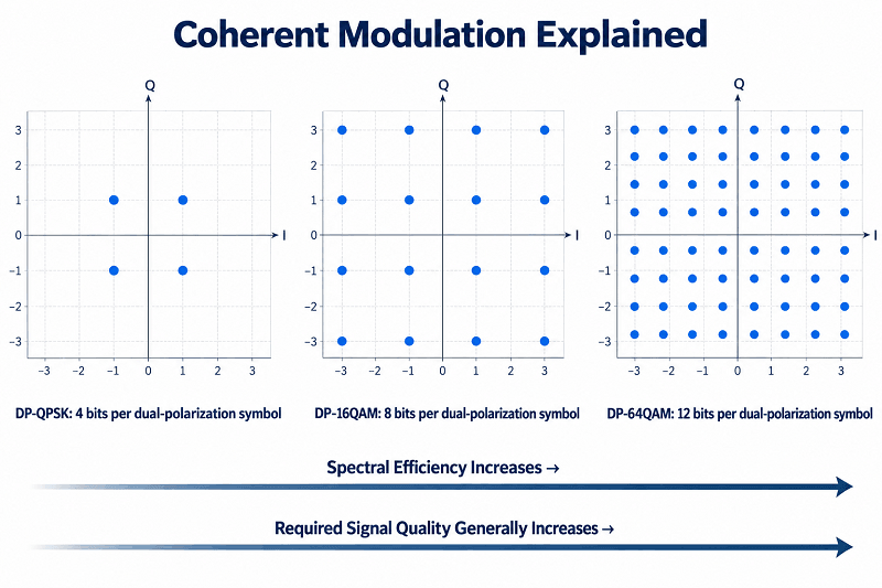
Inside the receiver, coherent detection mixes the incoming signal with a local oscillator laser. Optical hybrids and balanced photodetectors recover the in-phase and quadrature components on each of two polarizations. These four electrical signal components allow multiple information bits to be conveyed per dual-polarization symbol. DP-QPSK carries 4 uncoded bits per dual-polarization symbol, DP-16QAM carries 8, and DP-64QAM carries 12 before coding or constellation shaping.
What the DSP Removes
The digital signal processor (DSP) compensates for impairments that historically required separate optical components. Chromatic dispersion can be corrected electronically within the DSP’s supported range, so coherent long-haul networks generally do not need inline dispersion compensation modules. The DSP also tracks polarization changes, compensates for polarization-mode dispersion within its tolerance, and recovers carrier phase and frequency.
Forward error correction (FEC) further improves receiver performance, but coding gain is not the same as available link margin. Different coherent systems use different schemes—for example, C-FEC in OIF 400ZR and OFEC in OIF 800ZR—with distinct overhead, performance, and interoperability requirements. Modern coherent modules also provide signal-quality telemetry such as pre-FEC BER, estimated SNR/OSNR, and margin indicators, depending on the implementation. Our coherent optical module guide covers module families; this article assumes you have selected a candidate and now need to design the line.
Modulation, Baud Rate, and the OSNR Trade-off
Here is the relationship that drives coherent DWDM design decisions: carrying more information per symbol can increase capacity, but generally demands better signal quality. The exact OSNR penalty is not a universal 3 dB for every added bit; it depends on constellation geometry, baud rate, FEC, DSP generation, and operating conditions.
Moving from QPSK to 16QAM, or from 16QAM to 64QAM, typically raises the required SNR at a comparable symbol rate and error-performance target. That penalty can be the difference between a route that closes and one that needs a lower-rate mode, improved amplification, or regeneration.
| Format | Uncoded bits per dual-pol symbol | Illustrative rate / baud | OSNR guidance (0.1 nm reference) | Reach guidance |
| DP-QPSK | 4 | 100G at ~32 Gbaud | Often in the low-to-mid teens of dB, depending on FEC | May support thousands of kilometers on engineered systems |
| DP-8QAM | 6 | 150G at ~32 Gbaud | System- and FEC-dependent | Long-haul capability depends on the platform |
| DP-16QAM | 8 | 200G at ~32–40 Gbaud | System- and FEC-dependent | Hundreds to thousands of kilometers in suitable modes |
| DP-16QAM | 8 | 400G at ~60 Gbaud | OIF 400ZR receiver OSNR tolerance: 26 dB maximum; other 400G modes differ | OIF 400ZR: up to ~120 km amplified; optimized 400G transport/ZR+ systems may go farther |
| DP-64QAM | 12 | 600G at ~64 Gbaud (illustrative) | Higher OSNR is generally required; confirm exact mode | Usually shorter than lower-order modes under comparable conditions |
| DP-16QAM | 8 | 800G at ~118.2 Gbaud | OIF 800ZR receiver OSNR tolerance: 27 dB maximum | OIF 800ZR: 80–120 km, amplified, point-to-point |
| DP-64QAM with PCS | Variable; less than 12 for shaped constellations | 1.2T at ~130 Gbaud (implementation-specific) | Vendor- and operating-mode-dependent | Requires a product-specific reach/OSNR assessment |
These figures are illustrations, not interchangeable transceiver specifications. In particular, OIF 400ZR and 800ZR OSNR tolerances are specified for defined back-to-back reference conditions and do not automatically include real-world penalties from multiple spans, ROADMs, nonlinearities, or filtering. The required OSNR of a proprietary long-haul 400G system may differ considerably from that of a standardized 400ZR module. Comparing modules without matching their FEC mode, line rate, reference bandwidth, and test conditions is a costly mistake. The OIF 400ZR and OIF 800ZR implementation agreements define the relevant interoperable interfaces.
Channel Width Follows Baud Rate
An optical signal occupies a bandwidth related to its baud rate and pulse-shaping roll-off. Channel width is therefore not a free choice: it must accommodate the signal spectrum and the filter characteristics of the optical line system.
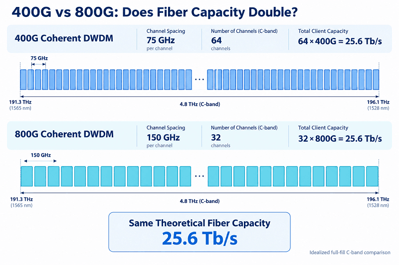
A ~32 Gbaud coherent signal may fit within a 50 GHz slot. A ~60 Gbaud 400G signal can use a 75 GHz channel with suitable filtering, or a 100 GHz channel in compatible networks. OIF 800ZR uses ~118.2 Gbaud and specifies 150 GHz channel spacing, which is why it cannot simply be inserted into an unchanged legacy 100 GHz filter plan. Higher-rate 800G ZR+ modes may have different line-system requirements.
This is where upgrade plans quietly fall apart. ITU-T G.694.1 defines fixed-grid frequencies and a flexible grid with 6.25 GHz center-frequency granularity and 12.5 GHz slot-width increments. Flex-grid equipment can allocate a 75 GHz slot instead of a 100 GHz slot where the hardware and system plan support it. Fixed 100 GHz filters do not automatically become flex-grid-capable through software. Our DWDM channels guide works through the grid arithmetic.
Probabilistic Constellation Shaping
Probabilistic constellation shaping (PCS) changes the probability distribution of transmitted constellation points to better match channel conditions. Rather than using every point equally often, it typically favors lower-energy points, improving the balance between achievable information rate and noise tolerance.
Depending on the implementation and comparison conditions, shaping can provide a meaningful SNR benefit, sometimes around 1 dB or more. Its more practical value is flexibility: on supported coherent platforms, operators can trade information rate for reach through selectable modulation and shaping modes. Such changes require the relevant DSP capabilities and supported operating profiles; they are not guaranteed to be software-only upgrades on every module.
Spectral Efficiency: What Coherent DWDM Does to Fiber Capacity
Now for the arithmetic the marketing number can hide.
Theoretical capacity equals spectral efficiency, measured in bits per second per hertz, multiplied by usable optical bandwidth. For uniformly spaced channels, nominal spectral efficiency is the client data rate divided by the allocated channel width. That calculation reveals why a higher line rate does not necessarily double total fiber capacity.
| Configuration | Channel width | Channels in ~4.8 THz C-band | Nominal spectral efficiency | Theoretical fiber capacity |
| 100G DP-QPSK | 50 GHz | 96 | 2.0 bit/s/Hz | ~9.6 Tb/s |
| 400G DP-16QAM | 75 GHz | 64 | 5.3 bit/s/Hz | ~25.6 Tb/s |
| 800G DP-16QAM | 150 GHz | 32 | 5.3 bit/s/Hz | ~25.6 Tb/s |
| 600G DP-64QAM | 100 GHz | 48 | 6.0 bit/s/Hz | ~28.8 Tb/s |
| 800G DP-16QAM, C+L | 150 GHz | ~64 across two bands | 5.3 bit/s/Hz | ~51.2 Tb/s |
These are simplified, full-fill theoretical examples, not deployment guarantees. Actual capacity depends on the usable amplified spectrum, channel alignment, filter passbands, guard requirements, line-system support, and achievable transmission performance. The 600G and C+L configurations also require suitable commercial operating modes and equipment.
A 400G coherent DWDM channel occupying 75 GHz and an 800G channel occupying 150 GHz provide the same nominal spectral efficiency: about 5.3 bit/s/Hz. Under the simplified full-fill model, both yield about 25.6 Tb/s per C-band fiber direction. What 800G can buy is fewer ports, fewer wavelengths to manage, and potentially lower cost per transported bit. What it does not automatically buy is twice the total fiber capacity.
That is Rafael’s illustrative route in one table. The proposal moves from 400G channels on a 100 GHz plan to 800G channels on a 150 GHz plan. Channel count falls from 48 to 32, while the rate per channel doubles. Total theoretical capacity rises from 19.2 Tb/s (48 × 400G) to 25.6 Tb/s (32 × 800G)—an increase of 33.3%, not fourfold. Even retaining all 48 original channels at 800G would only double capacity, and the proposed 150 GHz channel width prevents that channel count within the same ~4.8 THz spectrum.
C-Band, L-Band, and C+L
The commonly used extended C-band covers approximately 191.3–196.1 THz, providing roughly 4.8 THz of potential optical bandwidth, depending on the equipment. That gives an idealized 96 channels at 50 GHz or 48 at 100 GHz, subject to the actual operating range and filter plan.
Adding the L-band can approximately double usable optical spectrum where both bands are fully supported. It requires compatible L-band tunable optics, amplification, wavelength-selective switching, and optical line-system design. L-band 800G-capable coherent pluggables are available from some vendors, but product support, tuning range, and deployed capacity vary. C+L can be a substantial capacity upgrade, though it is a hardware and network-engineering project rather than a simple configuration change.
The ordering rule that saves money is to evaluate spectral efficiency before buying more spectrum. PCS and a tighter grid can be valuable, but only when supported by existing DSPs, filters, ROADMs, and management software. L-band expansion typically means additional optics and photonic-line equipment.
The Coherent DWDM Link Budget
Power budgets get considerable attention. In amplified coherent DWDM networks, OSNR is often the critical budget—but receive power, accumulated dispersion, filtering, nonlinear impairments, and FEC margin also matter.
For a simplified chain of identical EDFA-amplified spans, with equal per-channel power and gain approximately matching span loss, an ASE-limited estimate is:
OSNR (dB/0.1 nm) ≈ per-channel power at amplifier input (dBm) − amplifier noise figure (dB) − 10·log₁₀(number of amplifiers) + 58
The constant of approximately 58 applies near 1550 nm for a 0.1 nm (approximately 12.5 GHz) reference bandwidth and the assumptions of this simplified model. This formula is useful for a first check—not a substitute for a full end-to-end link simulation.
A Worked Example
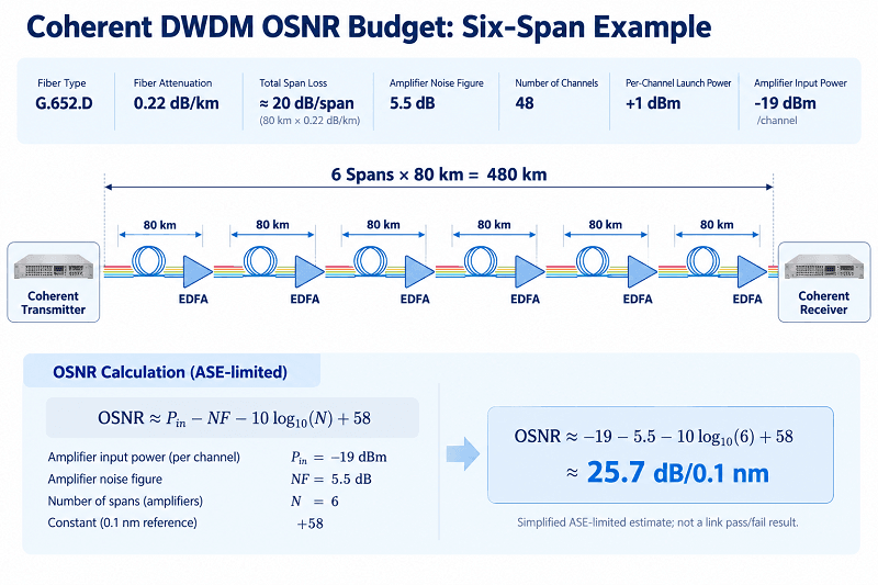
Take a six-span route. Each span has 80 km of G.652.D fiber at approximately 0.22 dB/km, plus 2 dB for splices and connectors. That is roughly 20 dB of span loss.
Assume each span amplifier supplies approximately 20 dB of gain with a 5.5 dB noise figure. The system carries 48 channels at approximately +17.8 dBm total launch power, equivalent to about +1 dBm per channel. This is a hypothetical operating point; a real design must validate the nonlinear optimum and equipment power limits.
After the 20 dB span loss, per-channel power at the next amplifier input is about +1 − 20 = −19 dBm. Into the simplified formula:
−19 − 5.5 − 10·log₁₀(6) + 58 ≈ 25.7 dB/0.1 nm
That result is only an estimated ASE-limited OSNR, not a pass/fail verdict. For example, it is below the 26 dB back-to-back OSNR tolerance limit of OIF 400ZR, even before other path penalties are included. Moreover, standard OIF 400ZR is intended for single-span DCI and cannot be assumed suitable for a six-span, 480 km route. A long-reach 400G transport transponder or an appropriately rated ZR+ mode may have a different OSNR requirement and much greater chromatic-dispersion tolerance. Whether any particular 400G, 600G, or 800G mode closes must be checked against the selected product specifications and the complete path penalties.
The engineering options remain familiar: reduce span loss, improve amplifier noise performance, optimize launch power and channel loading, select a lower-rate or more robust modulation mode, add Raman assistance where appropriate, or introduce regeneration. Reducing channel count can allow more power per channel within a fixed aggregate-power limit, but nonlinear penalties and amplifier behavior still need to be modeled.
Ready to check your own numbers? Send FiberMall the span count, fiber type, and target rate, and our engineers can review the OSNR budget against the modules and line system you’re considering. Request a line review.
Launch Power and Nonlinearity
Total launch power into a span cannot be increased indefinitely. The practical optimum depends on fiber type, effective area, channel count, baud rate, dispersion, and amplifier configuration; some dense C-band systems operate with aggregate launch power on the order of +17 to +21 dBm, but that range is not a universal limit. Above the optimum, extra launch power can cause more nonlinear distortion than useful OSNR improvement.
With a fixed total launch-power allowance, more channels generally mean less power per channel. Capacity and reach therefore compete for the same optical resources. Long-haul systems may use large-effective-area fibers such as G.654.E to reduce nonlinear penalties, although the best launch power and actual improvement still depend on the route and equipment.
ROADM Cascades and Passband Narrowing
Every ROADM or wavelength-selective switch (WSS) adds insertion loss that must be managed by the amplification plan. Cascaded WSS filtering can also narrow or distort the effective optical passband. High-baud signals are often more sensitive to inadequate passband width and filter misalignment than lower-baud signals.
Consider another illustrative metro-mesh case. Anika’s 400G design looks feasible for a 600 km point-to-point route, but the path actually crosses seven ROADM nodes. A simple fiber-and-amplifier calculation may miss cumulative WSS filtering penalties. Even with acceptable span losses and amplifier settings, the effective passband can become too restrictive for the chosen ~60 Gbaud signal.
Do not assume a fixed 0.5–1 dB OSNR-equivalent penalty for every ROADM hop. Penalties depend on WSS design, filter alignment, baud rate, channel slot width, crosstalk, and cascade depth. Use vendor filter data or end-to-end engineering simulations, and check the cumulative passband before committing to a high-baud configuration. Our DWDM OADM guide covers intermediate-node filtering, while EDFA in DWDM covers amplifier placement.
Transponder vs Coherent Pluggable (IPoDWDM)
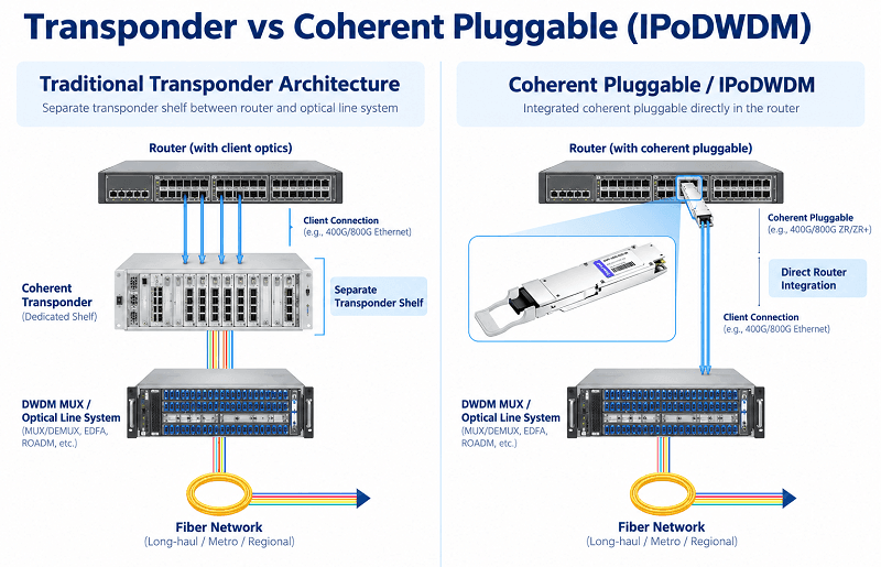
There are two common ways to put a coherent wavelength onto the line, and the choice depends as much on operational needs as on optical physics. A dedicated coherent DWDM transponder and a coherent pluggable provide similar line-side functions but integrate them into different parts of the network.
In the transponder model, client optics feed a transponder or muxponder card that performs optical-electrical-optical conversion and emits a DWDM wavelength. Depending on the platform and configuration, it may offer OTN framing, detailed performance monitoring, protection features, and multiservice aggregation. It also adds an optical shelf, power draw, and rack-space requirements.
In the IPoDWDM model, a compatible router or switch generates the coherent DWDM wavelength directly using a 400ZR, OpenZR+, 800ZR, or supported 800G ZR+ pluggable. A separate transponder shelf may no longer be necessary, though mux/demux units, amplifiers, ROADMs, and optical supervisory/management functions may still be required. In particular, OIF 800ZR targets approximately 80–120 km single-span amplified DCI, while some vendor-specific 800G ZR+ modes support longer metro and regional routes, in selected cases beyond 1,000 km.
Module-level detail, including form factors, power classes, and vendor compatibility, is covered in the 400G ZR QSFP-DD guide and the 800G ZR guide.
| Capability | Transponder | Coherent pluggable (IPoDWDM) |
| Reach | Metro, long-haul, or ultra-long-haul, depending on platform | 400ZR/800ZR: short DCI; ZR+ modes can extend to metro/regional and sometimes longer routes |
| OTN performance monitoring | Often extensive on OTN-capable platforms | Optical/FEC telemetry is common; OTN functions are implementation-dependent |
| Standardized protection | Available on suitably equipped systems | Usually provided by the host or network architecture; implementation-dependent |
| Multi-service aggregation | Often supported by muxponder/OTN platforms | Some coherent pluggables support multiple Ethernet clients; service aggregation is more limited |
| Footprint | Dedicated shelf or chassis capacity | Module in a compatible router/switch/transponder cage |
| Power | Includes the transponder shelf and associated overhead | Module power can be substantial, especially at 800G; verify host-cage support |
| Best fit | Complex, protected, multiservice, or demanding long-haul networks | DCI and IP-over-DWDM networks where router integration and host compatibility are suitable |
A pluggable is not simply a transponder in a smaller box. You may lose some OTN-centric management and protection functions, depending on the selected architecture, and must accommodate a high-power module inside a compatible host cage. In return, you may reduce footprint, system power, and the number of management domains.
Market researchers also expect continued growth. In its June 2026 forecast update, Dell’Oro Group projected the IPoDWDM market to grow at approximately 27% CAGR over the next five years and exceed $7 billion by 2030. Cignal AI has forecast more than 200,000 800ZR/ZR+ pluggable shipments in 2026. These are forecasts, not final shipment counts. Pluggables are becoming central to metro and regional transport, while dedicated transponder systems remain important for complex and demanding long-haul applications.
Mixing Coherent and Direct-Detect Channels
Many installed DWDM networks carry both types of traffic: legacy 10G direct-detect wavelengths and newer 400G coherent channels sharing fiber infrastructure and, where compatible, line-system amplification.
Filter width comes first. Legacy 10G wavelengths often operate comfortably on a 100 GHz plan. Some 400G coherent modes fit 75 GHz slots but can also operate in suitable 100 GHz channels, while standardized 800ZR needs 150 GHz spacing. A fixed 100 GHz mux/ROADM plan cannot automatically accommodate every 800G line signal or deliver flex-grid efficiency.
Launch power is second. Direct-detect and coherent channels may require different per-channel power targets, so power equalization and amplifier settings need to accommodate both signal types without excessive nonlinear penalties or insufficient receive margin.
OSNR is third—and often the most surprising. A 10G wavelength that has operated reliably for years may share a route that cannot support a particular 400G coherent mode, because the newer mode has different noise, dispersion, and filtering requirements. There is no universal 7 dB OSNR difference; compare the actual specifications and test conditions. The link may not have degraded, but the performance requirement has changed.
Plan the coherent spectrum and line-system requirements first, then place the legacy channels where both technologies can operate safely together.
Designing a Coherent DWDM Link
Seven steps, in order.
- Fix the endpoints and required capacity per wavelength.
- Measure or model span loss and span count, and identify the fiber type.
- Select the modulation and rate using the actual product mode specifications, not the marketing headline rate or a generic reach table.
- Calculate worst-case end-to-end OSNR and allow for nonlinear, filtering, and ROADM penalties.
- Check required channel width against the grid, mux/ROADM filters, and cumulative passband.
- Choose a transponder or coherent pluggable based on reach, host compatibility, protection, and monitoring needs.
- Verify amplifier gain range, gain flatness, receive-power limits, total launch power, and operating margins.
Then commission the link. Measure per-channel launch power into the first span and verify received OSNR against the engineered budget using an appropriate measurement method. Read pre-FEC BER, SNR, and available margin indicators from the coherent DSP, and confirm post-FEC error performance. Inspect the optical spectrum with an OSA to identify channel presence and tilt. Check the expected filter passband through each ROADM path, then document the as-built channel plan.
FiberMall supplies DWDM mux/demux units, including 50 GHz 96-channel configurations, OADMs, amplifiers, and tunable DWDM transceivers. Sourcing compatible elements together helps align the channel plan, connector interfaces, power budgets, and operational requirements—but complete end-to-end interoperability must still be verified.
The mistakes that cost the most are assuming that 800G automatically doubles fiber capacity, trying to place an 800ZR signal into an incompatible fixed 100 GHz filter plan, budgeting only for amplifier ASE while ignoring ROADM and nonlinear penalties, and comparing module OSNR values without matching the FEC mode and test conditions.
FAQ
What is coherent DWDM?
Coherent DWDM combines dense wavelength division multiplexing with coherent modulation and detection. DWDM carries multiple wavelength channels over the same fiber, while coherent processing supports multiple information bits per symbol on each wavelength. Depending on the system, this enables rates from approximately 100G to 1.2T or more per wavelength.
How far can coherent DWDM transmit?
Reach depends on the bit rate, modulation, FEC, DSP, fiber plant, and optical line system. Some 100G DP-QPSK systems can operate over thousands of kilometers. OIF 400ZR and 800ZR target up to approximately 120 km amplified point-to-point DCI, while selected 400G and 800G ZR+ or transponder modes can support much longer routes.
What OSNR does coherent DWDM need?
There is no single coherent DWDM OSNR requirement. As standardized examples, the OIF 400ZR receiver OSNR tolerance limit is 26 dB/0.1 nm, while the OIF 800ZR limit is 27 dB/0.1 nm under their specified reference conditions. Other formats and FEC modes may have different thresholds. Always confirm the relevant product mode and include system penalties and design margin.
Does coherent DWDM need dispersion compensation?
Usually not through separate optical DCMs. Coherent DSPs electronically compensate chromatic dispersion and track polarization-related impairments, within their specified limits. Very long or unusual routes still require validation against the transceiver’s supported dispersion range.
Can coherent and 10G DWDM channels share the same fiber?
Yes, provided the optical line system supports both types of signals. Check filter widths, frequency allocation, per-channel launch power, OSNR, amplifier gain flatness, and any additional crosstalk or nonlinear penalties.
Conclusion
Coherent DWDM changes what each wavelength can carry without removing the need for careful DWDM channel planning. Three things follow.
Total capacity depends on bits per hertz, not just bits per wavelength. In a simplified full-fill comparison, 400G in 75 GHz and 800G in 150 GHz deliver approximately the same fiber capacity, so channel planning matters as much as the module. OSNR is central to determining whether an amplified route can work, but it must be evaluated alongside receiver power, nonlinear effects, chromatic dispersion, filtering, and FEC performance. And a coherent pluggable is not always a drop-in replacement for a fully featured transponder platform.
For Rafael’s illustrative 640 km route, replacing the original capacity assumption with a defensible spectrum plan reveals the actual limit before equipment is ordered. The next step is to validate the selected 400G or 800G transport mode against the complete link budget—not to assume that a higher rate printed on the module guarantees the result.
Send FiberMall your span count, fiber type, channel plan, and target rate, and our optical transport engineers can review the design against real module specifications before you commit. Request a coherent DWDM line review.
Related Products:
-
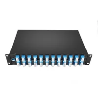
 DWDM MUX DEMUX 50GHZ 96CH (C15-C62) LC/UPC Dual Fiber 2U Rack
$6000.00
-
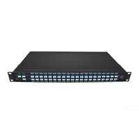
DWDM MUX DEMUX 40CH (C21-C60) LC/UPC Dual Fiber 1U Rack
$1100.00
-
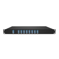
DWDM MUX DEMUX 16CH (C21-C36) with Monitor Port LC/UPC Dual Fiber 1U Rack
$800.00
-
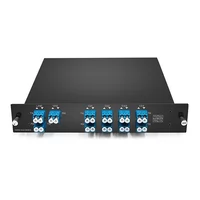
DWDM MUX DEMUX 8CH (C21-C28) with Express Port LC/UPC Dual Fiber LGX BOX
$500.00
-
DWDM MUX 8CH 16 Wavlengths (TX: C43/C45/C47/C49/C51/C53/C55/C57 RX: C44/C46/C48/C50/C52/C54/C56/C58) with MON Port LC/UPC Single Fiber LGX BOX
$450.00
-
SFP-DW10G17-40C 10G DWDM SFP+ C17 100GHz 1563.86nm 40km LC SMF DDM Transceiver Module
$155.00
-
SFP-DW10G17-80C 10G DWDM SFP+ C17 100GHz 1563.86nm 80km LC SMF DDM Transceiver Module
$175.00
-
SFP-DW10G17-100C 10G DWDM SFP+ C17 100GHz 1563.86nm 100km LC SMF DDM Transceiver Module
$235.00
-
SFP-DW10GTU-40C 10G DWDM Tunable SFP+ 50GHz 1529.55nm~1561.83nm 40km LC SMF DDM Transceiver Module
$550.00
-
SFP-DW10GTU-80C 10G DWDM Tunable SFP+ 50GHz 1529.55nm~1561.83nm 80km LC SMF DDM Transceiver Module
$750.00
-
OSFP-400G-DCO-ZR 400G Coherent OSFP-DCO ZR C-band Tunable Optical Transceiver Module
$7000.00
-
OSFP-400G-DCO-ZR+ 400G Coherent OSFP-DCO ZR+ C-band Tunable Optical Transceiver Module
$7000.00
-
OSFP-800G-DCO-ZR+-HTx 800G Coherent High TX Power OSFP DCO ZR+ C-band Tunable Optical Transceiver Module
$12000.00
-
OSFP-800G-DCO-ZR-HTx 800G Coherent High TX Power OSFP DCO ZR C-band Tunable Optical Transceiver Module
$11000.00
-
QSFP-DD-400G-DCO-ZR 400G Coherent QSFP-DD DCO C-band Tunable Optical Transceiver Module
$4550.00
-
QSFP-DD-400G-DCO-ZR+ 400G Coherent QSFP-DD DCO C-band Tunable Optical Transceiver Module
$4680.00
-
QSFP-DD-400G-DCO-ZR+-HTx 400G Coherent High TX Power QSFP-DD DCO OpenZR+ C-band Tunable Optical Transceiver Module
$5500.00
-
QSFP-DD-400G-DCO-ZR-HTx 400G Coherent High TX Power QSFP-DD DCO ZR C-band Tunable Optical Transceiver Module
$5200.00