
Consider an illustrative scenario: a nine-building hospital campus has one spare fiber pair, and a new imaging center is opening in six weeks. Installing additional duct would take eight months. Daniel, the network engineer on the project, needs nine 10G services running over the fiber pair the hospital already owns.
Most engineers in that position look at WDM first. Then they compare the cost and complexity of DWDM and look for a simpler option. CWDM can be the practical middle ground. It carries enough channels for many campus or metro links, uses passive mux/demux hardware that requires no local power, and can cost less to deploy than a comparable DWDM system. The endpoint transceivers still require power.
This guide covers how CWDM works, the 18-channel ITU wavelength grid, mux/demux insertion loss, reach limits, and when CWDM stops making sense. It also includes an illustrative link budget and a hardware checklist you can use when requesting a quote.
What Is CWDM?
CWDM, or coarse wavelength division multiplexing, combines multiple optical signals at different wavelengths on the same fiber. ITU-T G.694.2 defines 18 nominal center wavelengths, spaced 20 nm apart from 1271 to 1611 nm. The current G.695 (05/2025) Recommendation specifies standardized CWDM applications with up to 16 channels. Wide spacing relaxes laser and filter requirements, so CWDM commonly uses uncooled lasers and passive thin-film filters.
That definition is worth unpacking, because the word “coarse” explains almost every trade-off that follows.
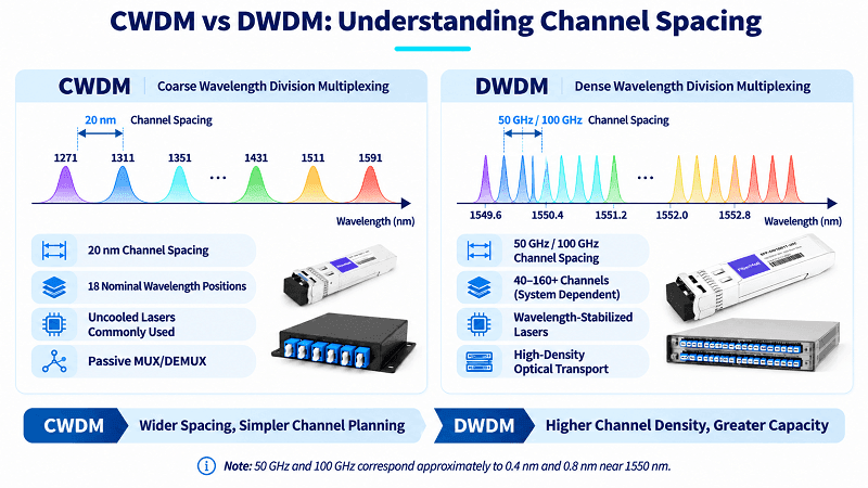
WDM is a family, not a single standard. A simple WDM arrangement may combine two wavelengths, such as 1310 and 1550 nm, on one fiber pair. CWDM extends this approach across up to 18 nominal wavelengths. DWDM packs many more channels into the same fiber using tighter spacing, commonly 50 or 100 GHz (about 0.4 or 0.8 nm near 1550 nm).
CWDM sits between simple two-wavelength WDM and high-density DWDM in capacity and complexity. It is often less expensive and simpler to deploy, although total cost depends on transceiver prices, channel count, reach, and amplification. Its capacity may suit campus, metro access, and selected 5G fronthaul links.
The technology exists for one reason: fiber is expensive and slow to install. Lighting a new strand can cost more than every piece of electronics on the link. CWDM lets you use existing fiber strands more efficiently.
If you are sizing a link right now, send the span length and channel count to our optical engineers. They will check the budget before you buy anything. Request a CWDM design review.
How CWDM Works: Uncooled Lasers and Thin-Film Filters
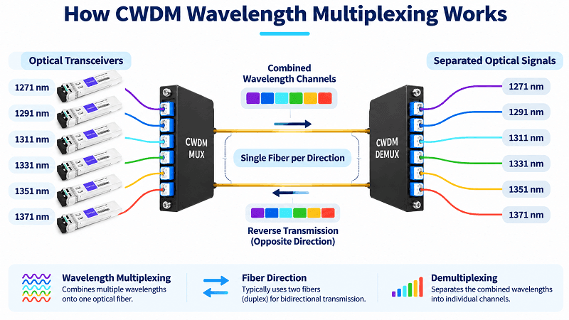
Each optical channel uses a transceiver tuned to a specific wavelength. At the transmitting end, a multiplexer combines the wavelengths onto one fiber. At the receiving end, a demultiplexer separates them into individual output ports. In a typical dual-fiber arrangement, one fiber carries each transmission direction.
Inside the mux, thin-film optical filters perform the wavelength selection. Each filter passes its assigned wavelength band and reflects or directs other wavelengths along the optical path. The resulting mux/demux module is passive: it has no power supply, firmware, or management interface. The endpoint transceivers, however, are active devices and require power. This simplicity can make CWDM useful in remote cabinets.
The lasers are the other half of the story. CWDM transceivers commonly use uncooled lasers. Their center wavelength shifts with temperature; the amount depends on the laser design and operating range. For some devices, about 0.1 nm per degree Celsius is a rough illustrative value, not a universal specification.
A 70 °C temperature change could therefore correspond to roughly 7 nm of drift in that example. The 20 nm spacing gives CWDM more tolerance than a dense grid, but the actual transmitter wavelength range must still remain within the mux’s specified passband.
DWDM channels sit 0.4 or 0.8 nm apart on the ITU-T G.694.1 grid. Such drift would be problematic on a dense grid, so many DWDM transceivers use cooled lasers or other wavelength-stabilization methods to maintain the required frequency accuracy. The exact implementation depends on the transceiver and application, and it can add cost, power consumption, and complexity.
FiberMall’s listed CWDM mux/demux products specify an ITU ±6.5 nm channel passband. This is a product-specific filter specification, not a universal tolerance for every CWDM device. Check the transmitter’s wavelength range over temperature against the passband of the exact mux/demux model.
Then there is amplification. Many passive CWDM links are designed without in-line optical amplifiers. Erbium-doped fiber amplifiers (EDFAs) commonly operate in the C-band, roughly 1530 to 1565 nm.
A C-band EDFA can amplify compatible CWDM channels within its gain band, including some channels near 1531 nm and 1551 nm, but it cannot amplify the full 1271–1611 nm grid. Check its gain range, flatness, power limits, and channel plan; wider coverage requires specialized solutions. The mux/demux path may be passive, but endpoint transceivers still require power.
CWDM vs DWDM: The 20 nm Difference That Decides Everything
The comparison comes down to spacing, and spacing drives everything else.
| Parameter | CWDM | DWDM |
| Channel spacing | 20 nm | 0.4 or 0.8 nm (50 or 100 GHz) |
| Channels per fiber pair | 18 nominal wavelength positions; G.695 applications cover up to 16 | 40 to 160+, depending on grid and band |
| Wavelength range | 1271 to 1611 nm | C-band, plus L-band |
| Laser type | Uncooled lasers are common | Wavelength-stabilized; cooling is common where required |
| Amplification | Often unamplified; selected C-band channels can use compatible EDFAs | EDFA widely used across the C-band |
| Typical reach at 10G | 80 km-class options are available; reach depends on the transceiver and link budget | Hundreds of km may be possible with suitable amplification and system design |
| System cost | Lower | Higher |
| Typical use | Metro, campus, 5G fronthaul | Long-haul, backbone, DCI |
One number surprises people: depending on product category, data rate, reach, and volume, a DWDM transceiver can cost less per module than a CWDM transceiver. That does not automatically make a DWDM system cheaper for a short link. Add the mux/demux, amplifiers, cooling, and engineering, and the total cost may favor CWDM. WWT’s decision guide discusses the choice from an integrator’s perspective.
For a full decision framework, including cost per usable channel and hybrid deployments, see our DWDM vs CWDM comparison. The dense side is covered in the DWDM complete guide.
The ITU-T G.694.2 Grid: All 18 CWDM Channels
ITU-T G.694.2 defines the CWDM grid. It sets 18 nominal center wavelengths, 20 nm apart, from 1271 to 1611 nm. Vendors often round the range to 1270-1610 nm. Same grid, rounded edges.
| Channel | Wavelength | Band | Notes |
| 1 | 1271 nm | O | Used in some 5G fronthaul designs |
| 2 | 1291 nm | O | Used in some 5G fronthaul designs |
| 3 | 1311 nm | O | Used in some 5G fronthaul designs |
| 4 | 1331 nm | O | Used in some 5G fronthaul designs |
| 5 | 1351 nm | O | Near O/E boundary |
| 6 | 1371 nm | E | Close to water peak |
| 7 | 1391 nm | E | Close to water peak |
| 8 | 1411 nm | E | |
| 9 | 1431 nm | E | |
| 10 | 1451 nm | E | |
| 11 | 1471 nm | S | Common metro channel |
| 12 | 1491 nm | S | |
| 13 | 1511 nm | S | |
| 14 | 1531 nm | C | Near the lower edge of the C-band |
| 15 | 1551 nm | C | Common metro channel |
| 16 | 1571 nm | L | Near the C/L-band boundary |
| 17 | 1591 nm | L | |
| 18 | 1611 nm | L |
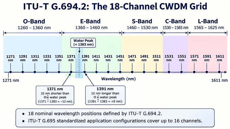
The 1371 nm and 1391 nm channels are nearest the water-peak region around 1383 nm, where hydroxyl-ion absorption can increase attenuation in older fiber. Low-water-peak fiber, such as G.652.C/D, significantly reduces this issue. Actual loss depends on fiber category and condition.
If the fiber type is unknown and the loss margin is tight, verify its attenuation profile before using these channels. Avoiding them may reduce risk on legacy fiber, but also reduces available capacity.
Many deployments use 4, 8, or 16 channels, depending on capacity and link budget. Metro and enterprise designs may use 1471–1611 nm, while selected 5G fronthaul designs use O-band wavelengths such as 1271–1331 nm, where dispersion is relatively low for 25G links. For the dense equivalent, see the DWDM channel plan and ITU grid.
CWDM Mux/Demux: Channel Counts, Insertion Loss, and Packaging
Choose a CWDM mux/demux by channel count, because insertion loss consumes the link budget at both ends. If the mux and demux have similar specifications, their combined loss is approximately twice the per-device value.
FiberMall specifies up to 1.2 dB insertion loss for its standard 4-channel module, up to 1.5 dB for certain 4-channel versions with a 1310 nm window, and up to 2.4 dB per unit for the listed 8-channel model. Some 18-channel designs can reach 5 dB per unit. These values are model-specific, not universal limits.
These figures are product-specific, not universal thin-film filter limits. They also show why a bigger mux isn’t automatically better.
| Spec | 4-channel | 8-channel |
| Insertion loss | ≤1.2 dB standard; up to ≤1.5 dB with a 1310 nm window, depending on model | ≤2.4 dB for the listed 8-channel model |
| Adjacent isolation | ≥30 dB | ≥30 dB |
| Non-adjacent isolation | ≥40 dB | ≥40 dB |
| Return loss | ≥45 dB | ≥45 dB |
| PDL | ≤0.2 dB | ≤0.2 dB |
| Max optical power | 500 mW | 500 mW |
| Operating temperature | -20 to +70 °C | -20 to +70 °C |
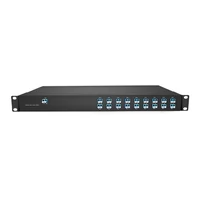
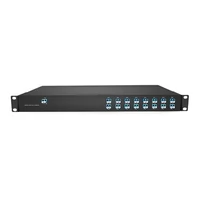
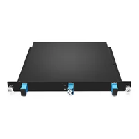
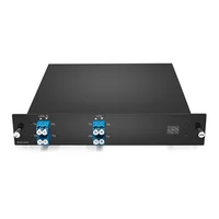
Packaging also matters. LGX boxes fit into standard rack shelves and are common in enterprise and metro installations. ABS box modules may be a lower-cost option, although they can be less convenient to integrate into a standardized rack. A 1U chassis makes sense when you need many ports in one place.
Watch for monitor and expansion ports. A monitor port taps a small fraction of the signal for testing, often specified as 1–5% or by coupling loss. Check its effect on the main path. An expansion port can add channels later, but verify its wavelength range, insertion loss, and compatibility before deployment.
In an illustrative example, Priya, a network engineer at a regional ISP, plans a 40 km metro ring. She specifies an 18-channel mux to leave room for growth. The selected unit has up to 5 dB of insertion loss per device, consuming much of the link budget and leaving two spans with less than 1 dB of margin.
Switching to an 8-channel module with an expansion port reduces loss to 2.4 dB per unit, or about 4.8 dB for the pair before connector losses. The revised design preserves a growth path and recovers optical margin.
FiberMall’s 4-channel LGX and 8-channel modules with a 1310 nm window are dual-fiber passive CWDM products with LC/UPC ports. Check each SKU’s specifications because loss and wavelength options differ.
CWDM Transceivers: Matching Colored SFPs at Both Ends
These transceivers are available in SFP, SFP+, and SFP28 form factors. Their key difference is that the laser is tuned to a specific ITU channel. A 10G CWDM SFP+ for channel 11 at 1471 nm must be paired with a compatible 1471 nm module in a typical dual-fiber link.
Pair transceivers by wavelength, data rate, fiber arrangement, and optical specifications—not part number alone. Dual-fiber links normally use the same wavelength at both ends; single-fiber BiDi links require complementary Tx/Rx wavelengths. Mixing reach grades may work if both modules meet the link budget and dispersion requirements, but can complicate support and spares.
Reach codes vary by data rate and model. 1.25G modules may offer 40, 80, or 120 km grades; 80 km-class 10G modules and 10–15 km O-band 25G modules are also available. These are product examples, not universal limits. Check the link budget and dispersion tolerance.
Compatibility is mostly about coding. Most vendors code modules for Cisco, Juniper, Arista, or generic MSA. Buy the right code or expect a port that refuses to come up. The same rule applies to any SFP or QSFP port on a switch.
For critical links, keep a compatible spare for each active wavelength or establish a tested replacement plan. A failed 1551 nm module cannot be replaced directly by a 1471 nm unit because the wavelength does not match.
Passive CWDM vs Active CWDM
The terms are not used consistently across the industry, so it helps to define them.
Passive CWDM uses unpowered optical components such as muxes, demuxes, and OADMs; endpoint transceivers still need power. “Active CWDM” is not a consistently standardized term and may refer to powered transponders, OEO regenerators, managed equipment, or amplification. A C-band EDFA can amplify selected C-band CWDM channels, not the entire grid, so check what a vendor means by “active”.
Passive CWDM is suitable when the optical budget closes without in-line regeneration or active optical-layer management. Network protection at the optical, Layer 2, or Layer 3 level is a separate design choice. Active equipment is needed for signal regeneration, protocol conversion, or remote optical-layer management.
A passive node has no local power supply or software to maintain, reducing powered components at remote sites. Passive devices can still fail, so connectors and fiber remain important inspection and troubleshooting points.
CWDM OADM: Adding and Dropping Channels Mid-Route
An optical add-drop multiplexer adds or drops selected channels at an intermediate site while the rest pass through. In a ring, each node might drop two channels and add two, while the others continue around the ring.
Single-fiber bidirectional OADMs use one strand for both directions, with separate wavelength groups for each direction. Dual-fiber OADMs use one strand per direction and can be easier to troubleshoot. The choice depends on fiber availability and protection design.
Fixed OADMs are passive and channel-specific. Reconfigurable equipment, such as a ROADM using wavelength-selective switching, costs more and requires power and control. Fixed OADMs are sufficient for many metro and access rings.
Reach and Link Budget: Why 80 km Is a Common 10G Design Reference
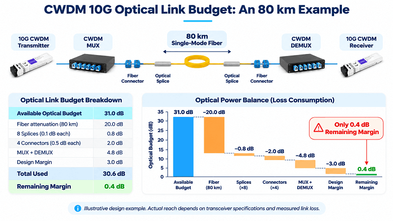
Here is an illustrative 10G, 80 km link budget with an 8-channel mux at each end. The transceiver values are assumptions; use the exact module’s minimum transmitter power, receiver sensitivity, overload limit, and dispersion tolerance for a real design.
| Item | Loss or margin |
| Assumed minimum transmitter launch power | +3 dBm |
| Assumed receiver sensitivity | -28 dBm |
| Total budget | 31.0 dB |
| Fiber, 80 km at 0.25 dB/km | 20.0 dB |
| Splices, 8 at 0.1 dB | 0.8 dB |
| Connectors, 4 at 0.5 dB | 2.0 dB |
| Mux plus demux, 2.4 dB per unit | 4.8 dB |
| Design margin | 3.0 dB |
| Total loss and design margin | 30.6 dB |
| Remaining margin | 0.4 dB |
A 0.4 dB margin is tight, not a universal value for an 80 km CWDM link. An extra splice, degraded connector, or unexpected loss could make this link marginal.
Dispersion can also limit 10G reach. Standard single-mode fiber has about 17 ps/nm/km of chromatic dispersion near 1550 nm, or roughly 1,360 ps/nm over 80 km. Acceptability depends on the transceiver’s dispersion tolerance and modulation format; some 10G optics may need a shorter span or dispersion compensation. Lower-rate links generally tolerate more dispersion, and some 1.25G products support 120 km or longer when the optical budget closes.
There is no universal amplifier solution for the full CWDM grid. If the budget does not close, shorten the span, use lower-loss components, add OEO regeneration, or choose an appropriate amplified transport design. DWDM may be more practical for long-distance, high-capacity links; specialized solutions can amplify selected CWDM bands.
CWDM Network Design: Metro, Campus, and DCI Edge
Start with the fiber you have, not the fiber you wish you had. Count strands, measure span loss, and identify the fiber type. Then count services and estimate growth.
Topology comes next. Point-to-point fits two sites. Linear fits a chain of buildings or huts. A ring gives you protection and is the usual choice for metro.
Channel planning saves money later. Assign wavelengths according to the service plan, check the fiber’s attenuation profile, and reserve unused channels for growth. If 5G fronthaul is planned, O-band wavelengths may be suitable when supported by the optics and fiber. Documenting the channel plan before deployment helps prevent field conflicts.
Growth needs a number, not a feeling. Choose an expansion port or a higher channel count only if the loss budget allows. An 18-channel mux on an 80 km span is often a design mistake disguised as future-proofing.
Hybrid CWDM/DWDM is another option. CWDM channels can use non-overlapping bands such as O- or E-band while DWDM uses the C-band, with suitable band filters combining them. Avoid spectral conflicts: CWDM channels at 1531 nm and 1551 nm also fall in the C-band and cannot simply share the same spectrum with C-band DWDM channels. Check filter passbands, isolation, amplifier coverage, and the link budget.
In an illustrative university deployment, Elena uses four CWDM channels across three buildings and a data center. A planned band-filter arrangement leaves room for a DWDM overlay in a non-overlapping band as research-computing demand grows, avoiding a second fiber build.
CWDM in 5G Fronthaul
5G fronthaul is one CWDM application. In some architectures, a distributed unit (DU) serves multiple remote radio units (RUs), and WDM assigns a wavelength to each RU or fronthaul link. The channel count depends on the DU/RU design and topology.
O-band channels from 1271 to 1331 nm are used in some fronthaul designs. Relatively low dispersion in this band can help 25G eCPRI links over single-mode fiber. These links are often 10 km or less, but reach must be checked against the optical-interface specifications and link budget.
Protection schemes vary by operator. Some use passive WDM add/drop nodes with redundant fiber paths; others use dual-star topologies. The goal is to prevent a single fiber cut or equipment fault from disrupting multiple radio connections. Fiber routing and protection design determine resilience.
CCWDM and Compact CWDM
CCWDM stands for compact CWDM. These modules reduce the size of the optical assembly and may use free-space optics or other compact filter arrangements instead of a conventional chain of fiber-coupled filters. Some designs also offer lower insertion loss, but the improvement depends on channel count, architecture, and connectorization.
The trade-offs may include cost per port, fewer channel options in some designs, and less familiarity among field technicians. For a space-constrained cabinet or a link with a tight loss budget, a compact module may be worthwhile. For a standard 1U rack, a conventional LGX module may be the simpler choice.
Deployment, Testing, and Troubleshooting
Commissioning a CWDM link requires a stabilized light source, calibrated power meter, connector inspection and cleaning kit, and documented link budget. An OSA is useful for channel-level analysis.
- Verify the fiber type and measure end-to-end loss with a stabilized light source and power meter or OLTS. Use an OTDR to locate splices, bends, and other loss events.
- Inspect and clean every connector, including the mux/demux ports. Dirty or damaged connectors are common causes of excessive loss and intermittent performance.
- Measure each channel at the mux output and demux output with a wavelength-selective power meter or OSA.
- Compare the measured values with the expected channel power and the calculated link budget.
- Use an OSA if one channel is low or distorted while the others are normal; this can help identify wavelength, filter, or isolation problems.
The usual faults are predictable: the wrong wavelength at one end, a dirty connector, swapped mux/demux ports, a damaged fiber, or a receiver overloaded by excessive optical power. Receiver overload can be easy to miss because the link may come up but produce errors under traffic.
If power is low at the mux output, check the transmitter and mux port. If it is normal there but low after the far-end demux, inspect the fiber, connectors, intermediate OADMs, and demux path. Use defined reference points to isolate the loss.
Choosing CWDM Hardware
A practical checklist for a quote request:
- Channel count today, plus the growth you can actually budget for
- Insertion loss at that channel count
- Packaging: LGX, 1U, or ABS
- Connector type and polish
- Fiber type, especially G.652 versus G.652.C/D
- Monitor and expansion ports
- Operating temperature for the enclosure
- Coding for your switch vendor
FiberMall offers CWDM mux/demux modules in 4-, 8-, and 16-channel configurations, with custom wavelength options and 1310 nm or 1550 nm windows on selected models. A 4-channel unit can suit a small campus link, while an 8-channel unit can cover many metro and enterprise builds. The right choice depends on the channel plan and available optical margin, not channel count alone.
If you are unsure which configuration fits your span, send the design to our engineers. They will model the budget and recommend a module rather than the largest one on the shelf. Talk to FiberMall.
FAQ
What is the difference between CWDM and DWDM?
CWDM uses a 20 nm grid with up to 18 nominal wavelength positions; standardized applications in the current ITU-T G.695 cover up to 16 channels. Many links operate without in-line amplification, although compatible C-band channels can use suitable EDFAs. DWDM uses tighter spacing, supports higher channel counts, and is widely used with optical amplification for long-haul systems.
How many channels does CWDM support?
G.694.2 defines 18 nominal wavelengths from 1271 to 1611 nm; standardized G.695 applications cover up to 16 channels. Commercial products may offer 4-, 8-, 16-, or 18-channel configurations. The practical limit depends on equipment, fiber, insertion loss, and link budget.
How far can CWDM transmit?
There is no single CWDM distance limit. Some 10G modules support up to about 80 km when fiber loss, mux/demux loss, receiver sensitivity, and dispersion tolerance allow it. Some 1.25G products support 120 km or longer. These distances are product- and link-dependent, so calculate the budget using the exact module specifications.
Can CWDM be amplified?
Yes. A compatible C-band EDFA can amplify selected CWDM channels, such as 1531 nm or 1551 nm, if they fall within its specified gain range. It cannot amplify the entire 1271–1611 nm grid; wider coverage requires specialized equipment. Many CWDM links remain passive because their budgets do not require in-line amplification.
Is CWDM4 the same as CWDM?
No. CWDM4 is a 100G data-center optical interface using four wavelengths—1271, 1291, 1311, and 1331 nm—with four 25-Gb/s-class optical lanes to carry an aggregate 100G signal over about 2 km of duplex single-mode fiber. It uses the CWDM grid but is a transceiver interface, not a multi-channel CWDM transport system. For the module side, see the QSFP28 module types guide in our QSFP28 cluster.
Is CWDM still used?
Yes. CWDM is still used in metro access, campus networks, and selected mobile fronthaul deployments where existing fiber must carry multiple services cost-effectively. Suitability depends on channel count, reach, and optical budget. 25G CWDM optics and hybrid CWDM/DWDM designs are used in some deployments.
The Short Version
CWDM is not a compromise technology. It is the correct answer for a large share of short-reach links, and the 20 nm grid is the reason.
Four things decide whether it fits your project. The span must close within the available optical budget, with any planned amplification included. The channel count must fit both the mux configuration and the insertion-loss budget.
The fiber’s attenuation must support the selected wavelengths, especially around the water-peak region. And the growth plan has to be real, not aspirational.
Get those factors right and CWDM can be simple, passive at the wavelength-multiplexing layer, and cost-effective to operate. Get them wrong and spare modules alone will not solve the link problem.
If you are planning a deployment, send us the span length, fiber type, channel count, and service mix. Our engineers will check the budget and put together a module list that fits. Request a CWDM design review.
Related Products:
-
 Passive CWDM Double Fiber Mux & Demux Module 18 CH (1270-1610nm) LC/UPC 1U Rack
$630.00
-
Passive CWDM Double Fiber Mux & Demux Module 16 CH (1310-1610nm) 1U Rack
$570.00
-
CWDM MUX 8CH 16 Wavelengths (TX: 1310/1330/1390/1410/1470/1490/1550/1570nm RX: 1350/1370/1430/1450/1510/1530/1590/1610nm) LC/UPC Single Fiber 1U Rack
$320.00
-
Passive CWDM Double Fiber Mux & Demux Module 8CH (1470-1610nm) LC/UPC LGX BOX
$280.00
-
CWDM MUX 4CH 8 Wavelengths (TX: 1470/1490/1510/1530nm RX: 1550/1570/1590/1610nm) with Express Port LC/UPC Single Fiber LGX BOX
$150.00
-
Passive CWDM Double Fiber Mux & Demux Module 4 CH (1470-1530nm) LC/UPC LGX BOX
$150.00
-
Passive CWDM Single Fiber 1 Channel OADM LGX BOX
$70.00
-
Passive CWDM Double Fiber 2 Channels OADM LGX BOX
$130.00
-
Passive CWDM Double Fiber 4 Channels OADM LGX BOX
$250.00
-
SFP-CW10G27-40C 10G CWDM SFP+ 1270nm 40km LC SMF DDM Transceiver Module
$95.00
-
SFP-CW10G27-10C 10G CWDM SFP+ 1270nm 10km LC SMF DDM Transceiver Module
$60.00
-
SFP-CW10G59-05C 10G CWDM SFP+ 1590nm 5km LC SMF DDM Transceiver Module
$60.00
-
SFP-CW10G27-20C 10G CWDM SFP+ 1270nm 20km LC SMF DDM Transceiver Module
$75.00
-
SFP-CW10G47-100C 10G CWDM SFP+ 1470nm 100km LC SMF DDM Transceiver Module
$280.00