

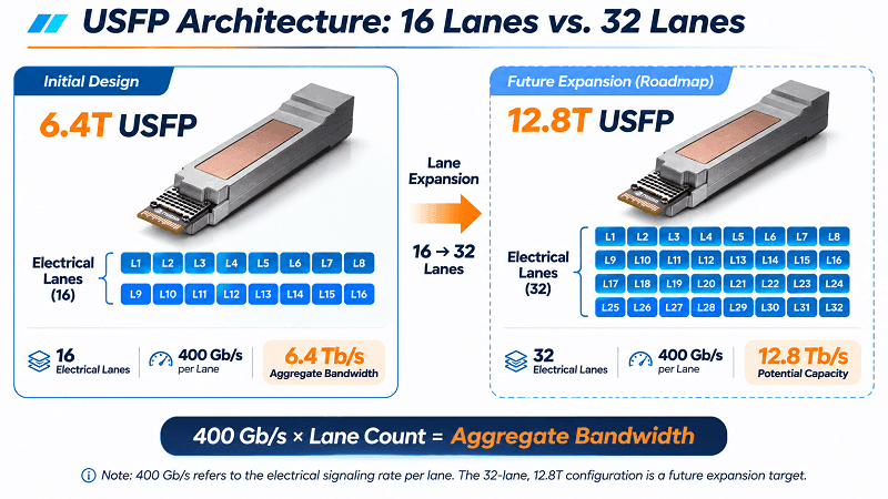
USFP is designed to scale from 6.4T to 12.8T by increasing its electrical lane count while supporting 400 Gb/s per lane. Its first planned transceivers use 16 full-duplex lanes, delivering 6.4 Tb/s of aggregate capacity. The connector architecture is designed to support future expansion to 32 lanes, potentially enabling 12.8 Tb/s. Announced by NVIDIA and Cisco at OCP Global Summit 2026, USFP is the first planned pluggable optical form factor designed to support 400 Gb/s-per-lane electrical signaling.
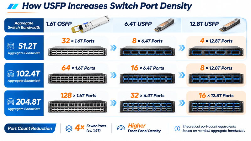
Here’s an important challenge facing AI fabrics: as switch ASIC bandwidth increases, front-panel density becomes an increasingly important constraint. A 51.2T switch could theoretically deliver its full aggregate port bandwidth through 32 separate 1.6T OSFP ports. An equivalent 6.4T USFP configuration would require just 8 ports. That means fewer switch-side cages and module interfaces, potentially simplifying cabling and front-panel management. Actual cable counts and network architecture will still depend on the optical design and system implementation.
What Is USFP Capacity?
USFP capacity refers to the aggregate bandwidth supported by a single Ultra-Dense Small Form Factor Pluggable module architecture. Its initial design uses 16 full-duplex electrical lanes operating at 400 Gb/s each, delivering 6.4 Tb/s. The connector architecture is designed to scale to 32 full-duplex lanes, potentially increasing aggregate capacity to 12.8 Tb/s.
The initial 16-lane design uses an OSFP-sized footprint. The 32-lane configuration represents a future expansion target rather than a currently finalized, commercially available module.
That’s the core concept in one sentence. For a deeper explanation of what USFP is, including its connector architecture, thermal design, and MSA development status, see our USFP Optical Module explainer and NAND Research’s technical breakdown of the technology.
The Lane Math: How USFP Reaches 6.4T and 12.8T
USFP’s capacity comes down to two factors: the number of electrical lanes and the data rate supported by each lane.
- 16 lanes × 400 Gb/s = 6,400 Gb/s = 6.4 Tb/s
- 32 lanes × 400 Gb/s = 12,800 Gb/s = 12.8 Tb/s
The second figure represents the longer-term scaling potential of the architecture. USFP is designed around 400 Gb/s-per-lane electrical signaling, while mainstream current-generation pluggable platforms are generally based on electrical interfaces of up to 200 Gb/s per lane.
For comparison, a 1.6T OSFP architecture uses 8 electrical lanes operating at 200 Gb/s each to deliver 1.6 Tb/s.
Why does the per-lane rate matter so much? Increasing the electrical signaling rate from 200 Gb/s to 400 Gb/s doubles the bandwidth available per lane. Combined with a higher lane count, this allows USFP to deliver substantially greater capacity within a compact pluggable architecture.
NVIDIA and Cisco describe USFP as the first planned pluggable optical form factor designed to support 400 Gb/s-per-lane electrical signals through next-generation SerDes technology. This refers to the electrical interface between the host system and the optical module, not necessarily the data rate carried by each individual optical fiber.
USFP Capacity vs Today’s Pluggable Modules
Here’s how USFP fits into the broader progression of pluggable module bandwidth:
| Generation | Form Factor | Electrical Lanes | Per-Lane Rate | Aggregate Capacity |
| 800G | OSFP / QSFP-DD | 8 | 100G | 0.8T |
| 1.6T | OSFP | 8 | 200G | 1.6T |
| 3.2T | OSFP-XD | 16 | 200G | 3.2T |
| 6.4T | USFP | 16 | 400G | 6.4T |
| 12.8T | USFP | 32* | 400G | 12.8T |
Note: The 3.2T OSFP-XD row represents the lane architecture defined in the OSFP-XD specification. The 6.4T USFP row represents its initial planned design, while the 32-lane, 12.8T configuration is a future expansion target.
Two developments stand out. First, USFP increases both the per-lane signaling rate and the potential lane count, moving from 16 lanes in its initial design to 32 lanes in its future expansion architecture.
Second, NVIDIA and Cisco expect USFP to deliver approximately 4× the bandwidth density and 1.3× the power efficiency of 200 Gb/s-per-lane optical modules. These are vendor-stated design expectations, with actual results depending on system and module implementations.
USFP also introduces a new two-dimensional array connector with a two-step insertion mechanism. High-speed electrical contacts engage after the module is inserted, helping reduce contact wear, improve signal integrity, and make insertion force more predictable.
The design supports power dissipation of up to 100W without requiring a separate, dedicated embedded cooling circuit within the transceiver. However, appropriate heatsink design and system-level airflow remain essential for thermal management.
For a closer look at how the new form factor compares with existing modules, read how USFP compares to OSFP and QSFP-DD.
What 6.4T and 12.8T Buy You: Switch and GPU Port Counts
Raw Tb/s figures can feel abstract until you translate them into port counts. Here’s how the theoretical bandwidth scales across three switch-capacity examples.
Switch Radix Examples
The following table illustrates the number of ports required to provide equivalent aggregate bandwidth using different module capacities.
| Aggregate Switch Port Bandwidth | 1.6T OSFP Ports | 6.4T USFP Ports | 12.8T USFP Ports |
| 51.2T | 32 | 8 | 4 |
| 102.4T | 64 | 16 | 8 |
| 204.8T | 128 | 32 | 16 |
These figures are theoretical bandwidth equivalents, calculated by dividing the aggregate switch port bandwidth by the nominal capacity of each port. They do not represent confirmed switch configurations or guaranteed port breakout support. Actual implementations depend on switch ASIC capabilities, port mapping, and system architecture.
At the 204.8T level, a future 12.8T USFP configuration could reduce the required switch-side port count from 128 to 16 compared with 1.6T ports. This illustrates the potential for higher-radix AI networks with fewer physical port interfaces.
Aggregating 1.6T SuperNIC and GPU Connections
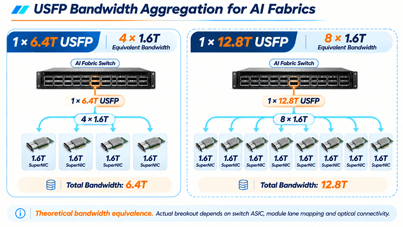
High-capacity switch ports are most useful when they can efficiently connect to downstream endpoints. From a bandwidth perspective, USFP offers substantial aggregation potential because its capacity scales in multiples of 1.6T:
- 1 × 6.4T USFP port = bandwidth equivalent to 4 × 1.6T connections
- 1 × 12.8T USFP port = bandwidth equivalent to 8 × 1.6T connections
This means a future 12.8T USFP port could provide aggregate bandwidth equivalent to eight 1.6T SuperNIC connections.
However, equivalent bandwidth does not automatically guarantee direct optical breakout. Actual configurations will depend on switch ASIC capabilities, module electrical lane mapping, optical connectivity, and endpoint interface specifications.
The potential benefit for AI clusters is clear: higher-capacity switch connections can help architects aggregate more accelerator-facing bandwidth while reducing the number of switch-side ports and simplifying network design.
Why Front-Panel Density Is the AI-Fabric Bottleneck
As AI workloads continue to grow, one of the key challenges in scaling AI fabrics is the physical density of network equipment. Switch ASICs continue to deliver higher bandwidth, but the front panel must also accommodate more high-speed connections within limited rack space.
Every additional 1.6T OSFP port requires physical space, power, a module interface, and an associated network connection.
Higher-capacity USFP ports can help address this challenge in several ways:
- Cabling: Fewer switch-side ports can simplify front-panel cabling and cable management. The actual number of cable assemblies and fiber connections depends on the optical architecture and breakout configuration.
- Failure Domains: Fewer switch-side cages and module interfaces can reduce the number of potential failure points at the switch front panel. End-to-end reliability still depends on the entire optical link.
- Switching Tiers: Higher port bandwidth and switch radix can potentially reduce the number of network tiers, although the actual topology depends on endpoint count, oversubscription ratio, and available ASIC capabilities.
- Power Efficiency: NVIDIA and Cisco expect approximately 1.3× better power efficiency compared with 200 Gb/s-per-lane optical solutions. Actual system-level power savings depend on module consumption, cooling requirements, and network implementation.
Reducing network tiers can eliminate an additional switching stage, lower associated equipment power consumption, and simplify network operations. However, this requires sufficient switch radix and appropriate network architecture.
USFP’s higher bandwidth density provides another path toward building more scalable AI fabrics without simply adding more switch ports and network layers.
The 12.8T Caveat: Capacity Ahead of the Silicon
There’s an important technical limitation to consider: publicly announced switch platforms have not yet demonstrated a production 400 Gb/s-per-lane SerDes interface specifically intended for USFP deployment.
Today’s high-end Ethernet switch ASICs use different SerDes generations. For example, Cisco’s Silicon One G302 is a 51.2T switching processor featuring 224G-generation SerDes technology. NVIDIA’s Spectrum-6 supports 102.4T switching capacity using 200 Gb/s PAM4 SerDes.
Neither of these published platform specifications identifies a 400 Gb/s-per-lane electrical interface for USFP.
USFP is designed to support the transition from 200G to 400G-per-lane electrical signaling. Cisco has also described a development path supporting both 200G and 400G SerDes-based systems and ASICs, potentially helping bridge current and next-generation Ethernet platforms.
Another important consideration is the specification’s development status. NVIDIA and Cisco have announced plans to establish an open industry specification through an upcoming community-led Multi-Source Agreement (MSA) project. However, a finalized public specification, sampling schedule, and commercial production timeline have not yet been announced.
In practical terms, the 6.4T and 12.8T figures describe the planned capacity of the USFP architecture, not currently shipping commercial transceiver products. The technology represents a roadmap that will require compatible switch silicon, optical modules, connectors, and system-level validation before large-scale deployment.
Planning Your Fabric Around USFP Capacity
If you’re building an AI fabric over the next 12 to 18 months, continue evaluating and deploying 800G and 1.6T modules where they meet your bandwidth and platform requirements. These technologies are more mature and have established deployment ecosystems, subject to platform compatibility.
Treat 6.4T and 12.8T USFP as design targets for the next generation of AI networking. It makes sense to consider higher port-density requirements in future rack layouts and network architectures, but avoid committing to unannounced USFP configurations before the specifications and compatible hardware become available.
Here are three important developments to watch:
- 400G-per-lane switch ASIC announcements: Compatible switch silicon will be essential for realizing the full potential of USFP.
- USFP MSA development: Watch for the publication of the open industry specification, including connector details, electrical interfaces, and lane mapping.
- Module sampling and commercial availability: Initial 6.4T USFP transceiver samples and subsequent production announcements will help determine the technology’s practical deployment timeline.
FiberMall supports the transition from the 200G-per-lane generation toward higher-speed AI networking. Today, that includes 400G and 800G optical modules, DAC and AOC cables for AI fabrics, and compatibility testing across major switch platforms.
As 400G-per-lane electrical interfaces move closer to commercial deployment, understanding the relationship between transceiver bandwidth, switch port density, and network architecture will become increasingly important.
For a broader view of the future bandwidth roadmap, see the 1.6T to 3.2T transceiver roadmap.
USFP Capacity: Frequently Asked Questions
What is USFP capacity?
USFP’s initial planned design supports 16 electrical lanes at 400 Gb/s each, delivering 6.4 Tb/s of aggregate capacity. Its connector architecture is designed to support future expansion to 32 lanes, potentially increasing capacity to 12.8 Tb/s.
How does USFP reach 12.8T?
USFP is designed to reach 12.8 Tb/s by expanding from 16 to 32 full-duplex electrical lanes while maintaining a signaling rate of 400 Gb/s per lane.
32 × 400 Gb/s = 12,800 Gb/s = 12.8 Tb/s.
This is a future expansion target rather than a currently shipping module configuration.
What is the difference between 6.4T and 12.8T USFP?
The main difference is the number of electrical lanes. The initial 6.4T design uses 16 lanes at 400 Gb/s each, while the future 12.8T architecture is designed to support 32 lanes at the same signaling rate.
The initial 16-lane design uses an OSFP-sized footprint. The detailed mechanical implementation of future 32-lane configurations has not yet been fully published.
How many lanes does USFP have?
The first planned USFP transceivers use 16 full-duplex electrical lanes, each supporting up to 400 Gb/s. The connector architecture is designed to scale to 32 lanes and potentially more in future configurations.
How does 400G per lane scale to 12.8T?
The scaling is based on multiplying the number of electrical lanes by the signaling rate per lane:
32 lanes × 400 Gb/s = 12.8 Tb/s.
The move from 200G to 400G-per-lane electrical signaling, combined with a higher lane count, enables substantially greater aggregate bandwidth.
How many 1.6T links is a USFP port equivalent to?
From a theoretical bandwidth perspective, a 6.4T USFP port provides the equivalent capacity of four 1.6T connections, while a future 12.8T configuration provides the equivalent capacity of eight 1.6T connections.
Actual optical breakout configurations will depend on switch ASIC support, module lane mapping, optical connectivity, and endpoint compatibility.