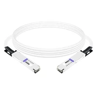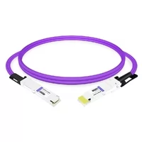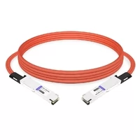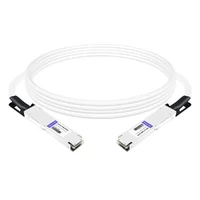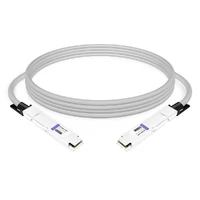

What Are DAC Cable Types?
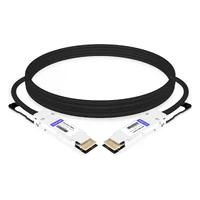
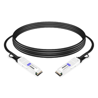
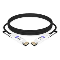
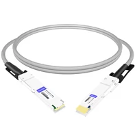
Direct Attach Copper (DAC) cables are commonly classified by four independent attributes: signal conditioning, connector form factor, connection topology, and application.
These attributes determine how a DAC cable connects to networking equipment, how it handles electrical signals, and which network environments it supports.
| Classification | Main Types | What It Defines |
| Signal conditioning | Passive, ACC, AEC | How electrical signals are transmitted and conditioned |
| Connector form factor | SFP+, SFP28, SFP-DD, QSFP28, QSFP-DD, OSFP, etc. | Physical interface and electrical lane architecture |
| Connection topology | Straight-through, Breakout | How ports are connected |
| Application | Ethernet, InfiniBand, Fibre Channel, AI fabrics | Network protocol and deployment environment |
A DAC cable’s data rate is determined by its electrical lane configuration and supported host interface. Speed is an important product specification, but it is not a separate physical cable type.
For example, two 400G DAC cables may use QSFP112, QSFP-DD, or OSFP connectors. Although they offer the same nominal aggregate data rate, their physical interfaces, lane configurations, and platform compatibility can differ.
Understanding these differences helps buyers select the correct cable for their switches, servers, and network adapters.
DAC Cable Types by Signal Conditioning: Passive, ACC, and AEC
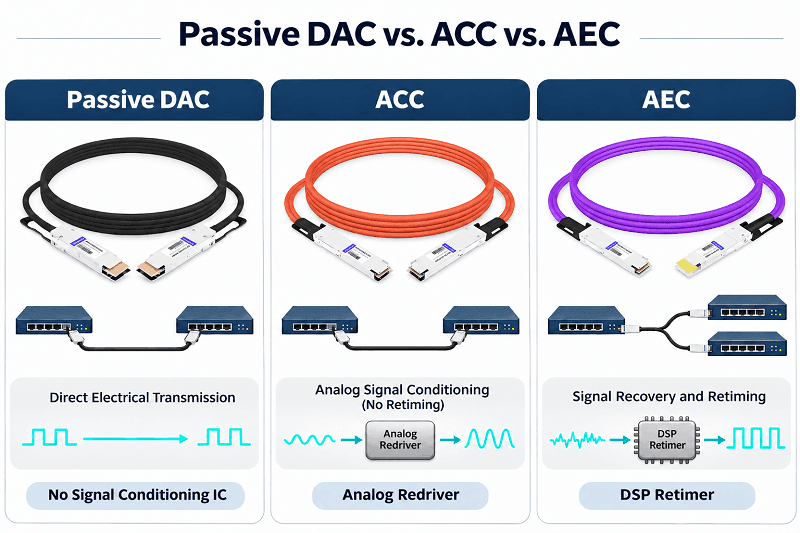
DAC cables are divided into three main categories based on how they handle electrical signals: passive DAC, Active Copper Cable (ACC), and Active Electrical Cable (AEC).
Passive DAC Cables
A passive DAC cable consists of twinaxial copper conductors and connectors at both ends, without active signal-conditioning components in the signal path.
The host device’s SerDes circuitry drives and receives the electrical signals, while its equalization capabilities compensate for channel losses.
Key characteristics include:
- No active redriver or retimer in the cable.
- Very low power consumption.
- Low latency.
- Lower cost than most active copper alternatives.
- Shorter transmission reach, particularly at higher data rates.
Passive DAC cables are commonly used for short connections between servers, switches, and storage devices within the same rack.
They are generally the preferred option when the cable length falls within the electrical channel budget of the host platform.
ACC: Active Copper Cables
An Active Copper Cable (ACC) incorporates analog signal-conditioning circuitry, typically using a redriver or linear equalizer.
The circuitry compensates for high-frequency signal attenuation and helps maintain signal integrity over longer copper connections.
Compared with passive DAC cables, ACC offers:
- Extended reach in supported configurations.
- Improved signal conditioning.
- Lower power consumption than many retimed AEC implementations.
- Moderate additional cost and power requirements.
However, a redriver does not retime the data. It cannot restore timing information in the same way as a retimer, and it may also amplify existing noise and jitter.
ACC is useful when a passive DAC cannot meet the required channel budget but an optical connection is not necessary.
AEC: Active Electrical Cables
An Active Electrical Cable (AEC) uses retiming circuitry to recover and retime electrical signals.
Unlike a redriver-based ACC, an AEC can restore signal timing through retiming, improving signal integrity over challenging copper channels.
Key characteristics include:
- Longer reach than many passive DAC implementations.
- Improved signal integrity through retiming.
- Higher power consumption.
- Higher cost than passive DAC cables.
- Additional thermal and power-management considerations.
AEC is increasingly used in high-speed data center networks, particularly for 400G and 800G connections where passive copper reach is limited.
Actual performance depends on the retimer chipset, cable construction, host interface, and product qualification.
Passive DAC vs. ACC vs. AEC
| Feature | Passive DAC | ACC | AEC |
| Signal-conditioning IC | None | Redriver / Equalizer | Retimer |
| Signal retiming | No | No | Yes |
| Power consumption | Very low | Low to moderate | Higher |
| Transmission reach | Short | Extended | Generally longer |
| Cost | Lowest | Moderate | Higher |
| Typical application | Short in-rack links | Extended copper links | High-speed copper interconnects |
Power consumption and maximum reach are product-specific. Always check the manufacturer’s datasheet rather than applying a universal value to an entire cable category.
Note: An Active Optical Cable (AOC) is different from an active DAC. An AOC uses optical fibers and integrated electro-optical conversion at both ends, rather than copper conductors.
DAC Cable Types by Form Factor and Speed (10G to 1.6T)
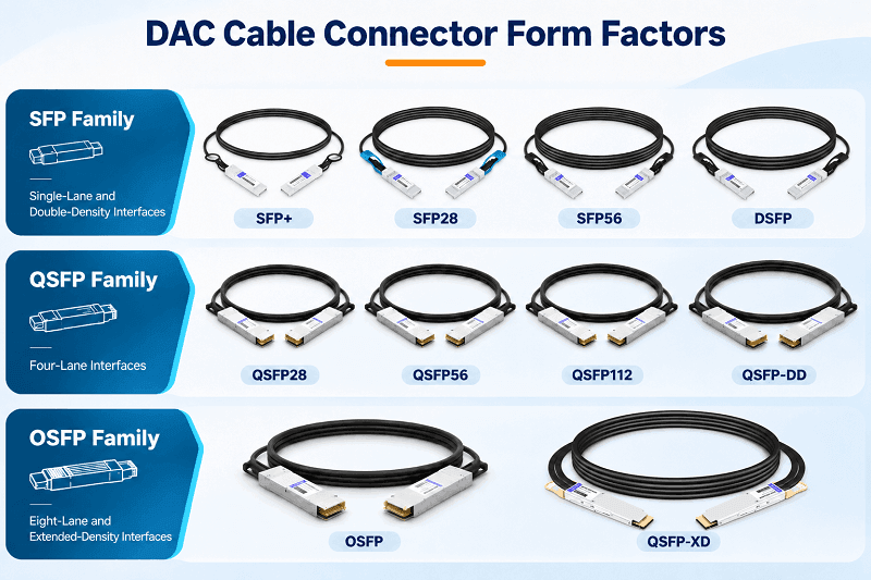
DAC cable form factors determine the physical connector design and the electrical interface architecture.
Different form factors support different numbers of electrical lanes and signaling rates.
The following table summarizes representative form factors and their common nominal data rates.
DAC Cable Form Factor and Speed Comparison
| Form Factor | Electrical Lanes | Gross Rate per Lane | Nominal Aggregate Rate | Modulation |
| SFP+ | 1 | 10.3125 Gb/s | 10G | NRZ |
| SFP28 | 1 | 25.78125 Gb/s | 25G | NRZ |
| SFP56 | 1 | 53.125 Gb/s | 50G | PAM4 |
| SFP112 | 1 | 106.25 Gb/s | 100G | PAM4 |
| SFP-DD | 2 | 53.125 Gb/s | 100G | PAM4 |
| DSFP | 2 | 53.125 Gb/s | 100G | PAM4 |
| SFP-DD112 | 2 | 106.25 Gb/s | 200G | PAM4 |
| QSFP+ | 4 | 10.3125 Gb/s | 40G | NRZ |
| QSFP28 | 4 | 25.78125 Gb/s | 100G | NRZ |
| QSFP56 | 4 | 53.125 Gb/s | 200G | PAM4 |
| QSFP112 | 4 | 106.25 Gb/s | 400G | PAM4 |
| QSFP-DD | 8 or 4 | 53.125 or 106.25 Gb/s | 400G | PAM4 |
| QSFP-DD800 | 8 | 106.25 Gb/s | 800G | PAM4 |
| QSFP-DD1600 | 8 | 212.5 Gb/s | 1.6T | PAM4 |
| OSFP | 8 | 53.125 Gb/s | 400G | PAM4 |
| OSFP800 | 8 | 106.25 Gb/s | 800G | PAM4 |
| OSFP1600 | 8 | 212.5 Gb/s | 1.6T | PAM4 |
| OSFP-XD | 16 | 106.25 or 212.5 Gb/s | 1.6T or 3.2T | PAM4 |
The figures represent common electrical interface configurations and nominal aggregate data rates. Not every MSA-defined configuration is necessarily available as a commercial passive DAC product.
Gross signaling rate per lane should also be distinguished from nominal aggregate data rate because encoding and transmission overhead affect the relationship between electrical signaling and usable data throughput.
SFP Family: Single-Lane and Double-Density Interfaces
The SFP family includes several generations of single-lane interfaces.
- SFP+: Commonly used for 10G Ethernet connections.
- SFP28: Supports 25G Ethernet connections.
- SFP56: Supports 50G PAM4 signaling over one electrical lane.
- SFP112: Supports 100G PAM4 signaling over one electrical lane.
SFP-DD and DSFP introduce two-lane architectures to increase port density.
Although both can support 100G configurations using two 50G lanes, they are different mechanical and electrical interface designs. Buyers should not assume that SFP-DD and DSFP assemblies are interchangeable.
SFP-DD112 extends the two-lane architecture to 200G using two 100G electrical lanes.
QSFP Family: Four-Lane Interfaces
The QSFP family uses four electrical lanes in its traditional configurations.
- QSFP+: Four 10G lanes for 40G.
- QSFP28: Four 25G NRZ lanes for 100G.
- QSFP56: Four 50G PAM4 lanes for 200G.
- QSFP112: Four 100G PAM4 lanes for 400G.
QSFP112 supports higher electrical lane rates while retaining a QSFP-style interface.
Its compatibility must be checked against the specific host port and supported electrical configuration.
Double-Density Interfaces: QSFP-DD and OSFP
QSFP-DD and OSFP were developed to support higher bandwidth through eight-lane electrical architectures.
Both support multiple generations of electrical signaling.
| Interface | Common Bandwidth | Electrical Architecture |
| QSFP-DD | 400G | 8 × 50G or supported 4 × 100G configurations |
| QSFP-DD800 | 800G | 8 × 100G |
| QSFP-DD1600 | 1.6T | 8 × 200G |
| OSFP | 400G | 8 × 50G |
| OSFP800 | 800G | 8 × 100G |
| OSFP1600 | 1.6T | 8 × 200G |
| OSFP-XD | 1.6T / 3.2T | 16 × 100G / 16 × 200G |
QSFP-DD maintains the QSFP-style mechanical footprint while adding a second row of electrical contacts.
Its MSA specifications provide backward compatibility with supported QSFP+ modules.
OSFP uses a different, larger physical design. Standard OSFP modules typically feature integrated heatsinks to manage thermal requirements. OSFP-RHS is an exception that requires a separate riding heatsink.
OSFP-XD is a separate extended-density interface with 16 electrical lanes. It is not mechanically interchangeable with standard OSFP.
Important: A 400G, 800G, or 1.6T label does not identify a unique connector type. Always confirm the form factor and electrical lane architecture before ordering.
Straight-Through vs. Breakout DAC Cables
DAC cables are also classified by connection topology.
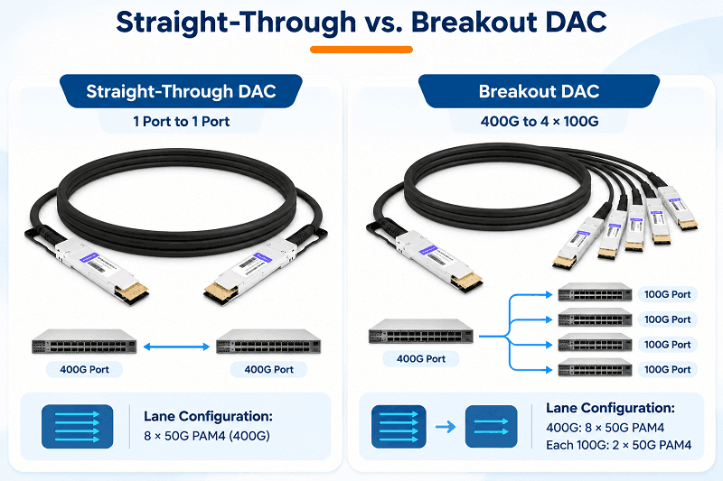
A straight-through DAC connects one networking port to another port.
A breakout DAC connects one high-speed port to multiple lower-speed ports by routing groups of electrical lanes to separate connectors.
Straight-Through DAC
A straight-through DAC has matching connector types and compatible electrical interfaces at both ends.
Typical applications include:
- Server-to-switch connections.
- Switch-to-switch connections.
- Storage-to-switch connections.
- Short-distance connections within a data center rack.
Examples include QSFP28-to-QSFP28 100G DAC and QSFP-DD-to-QSFP-DD 400G DAC.
Breakout DAC
A breakout DAC uses one high-density connector at one end and multiple connectors at the other end.
Common examples include:
| High-Speed Port | Example Breakout | Typical Application |
| 40G QSFP+ | 4 × 10G SFP+ | 10G server connections |
| 100G QSFP28 | 4 × 25G SFP28 | 25G server connections |
| 200G QSFP56 | 2 × 100G or 4 × 50G | Server and switch uplinks |
| 400G QSFP-DD / OSFP | 4 × 100G-2 or 2 × 200G-4 | Leaf-spine connections |
| 800G QSFP-DD800 / OSFP800 | 2 × 400G, 4 × 200G, or 8 × 100G | High-density AI and data center networks |
| 1.6T OSFP1600 / OSFP-XD | Platform-specific configurations | Emerging high-speed fabrics |
The breakout examples above are not universal interoperability guarantees. The exact electrical lane mapping and supported port modes depend on the switch, network adapter, cable assembly, and interface specifications.
For example, a 400G port configured as four 100G-2 interfaces uses two 50G PAM4 electrical lanes for each 100G branch. A compatible passive breakout cable can route these lanes to four supported 100G ports.
A passive breakout cable does not perform protocol conversion or independently change signal modulation.
If the source and destination interfaces require different electrical signaling, an appropriate active conversion or gearbox solution may be necessary.
Important Breakout Configuration Requirements
A breakout cable alone cannot split a high-speed port.
The switch must support the required breakout configuration, and the port must be configured accordingly.
Before ordering, verify:
- Whether the switch supports the required breakout mode.
- The number of electrical lanes available on the source port.
- The electrical signaling supported by each destination port.
- The required cable type and connector configuration.
- Whether the selected cable is qualified for the specific switch model.
DAC Cable Connector Compatibility: What Plugs Into What?
Connector compatibility is one of the most important considerations when purchasing DAC cables.
However, mechanical compatibility does not automatically guarantee electrical or operational compatibility.
The following rules provide a practical starting point.
| Module / Cable Interface | Host Port | Compatibility Considerations |
| SFP+ | SFP28 | Common backward-compatible combination; typically operates at 10G when supported |
| SFP28 | SFP+ | 25G operation is not supported by an SFP+ host; verify module and host compatibility |
| SFP112 | SFP28 / SFP+ | MSA provides lower-speed backward compatibility; host implementation must support it |
| SFP-DD | SFP-DD | Compatible matching interface required |
| DSFP | DSFP | Compatible matching interface required |
| SFP-DD | Standard SFP+ / SFP28 cage | Not mechanically interchangeable |
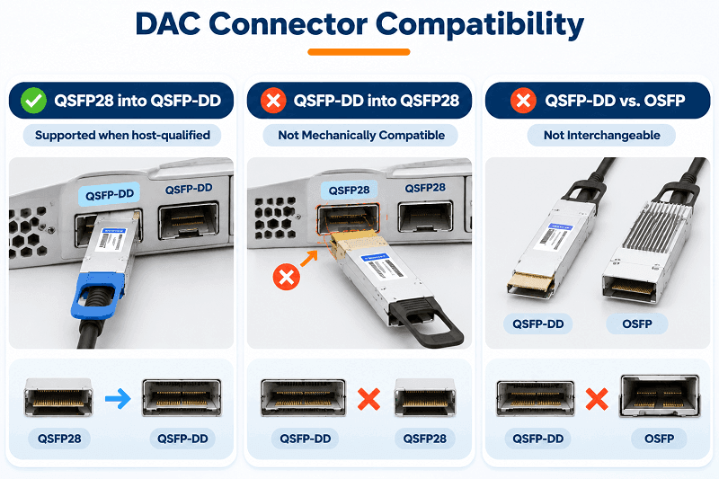
| QSFP28 | QSFP-DD | Backward-compatible physical interface; host configuration and module support still matter |
| QSFP-DD | QSFP28 | Not mechanically interchangeable |
| QSFP-DD | OSFP | Not mechanically interchangeable |
| OSFP | OSFP | Compatible matching interface required |
| OSFP | OSFP-XD | Not mechanically interchangeable |
SFP Compatibility
SFP+, SFP28, and SFP112 belong to related interface generations.
The SFP112 MSA specifies backward-compatibility provisions for supported SFP+ and SFP28 configurations.
However, compatibility must be checked in the correct direction. A newer module’s ability to operate in an older host at a lower rate does not mean every older host supports every newer module.
SFP-DD and DSFP should also be treated as distinct interfaces.
QSFP Compatibility
QSFP28 modules can be used in supported QSFP-DD cages because QSFP-DD was designed with backward compatibility for earlier QSFP modules.
The reverse is not true: a QSFP-DD module cannot be inserted into a standard QSFP28 cage.
QSFP-DD vs. OSFP
QSFP-DD and OSFP are different physical connector systems.
They are not interchangeable in either direction.
Although both support high-speed eight-lane electrical interfaces, their mechanical dimensions, cage designs, and thermal implementations differ.
OSFP vs. OSFP-XD
OSFP-XD uses a separate mechanical and electrical design with 16 electrical lanes.
Standard OSFP modules and OSFP-XD modules cannot be directly interchanged.
Mechanical Compatibility Is Only the First Step
Even when two connectors physically fit, several additional factors determine whether a DAC link will work:
- EEPROM identification and vendor coding.
- Host firmware and module support.
- Supported electrical signaling rates.
- SerDes capabilities and channel equalization.
- FEC configuration.
- Cable length and signal integrity.
Always check the switch or network adapter compatibility list before purchasing.
DAC Cable Types for Ethernet, InfiniBand, Storage, and AI
Different networking environments use DAC cables with different protocols, electrical requirements, and qualification processes.
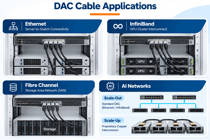
Ethernet DAC Cables
Ethernet DAC cables are widely used in data centers for server access, top-of-rack connections, and leaf-spine network architectures.
Common commercial product categories include:
- 10G DAC.
- 25G DAC.
- 40G DAC.
- 100G DAC.
- 200G DAC.
- 400G DAC.
- 800G DAC.
IEEE Ethernet copper PHY specifications use CR designations for different lane configurations.
Examples include:
- 25GBASE-CR.
- 40GBASE-CR4.
- 100GBASE-CR4 and 100GBASE-CR2.
- 200GBASE-CR4 and 200GBASE-CR2.
- 400GBASE-CR4.
- 800GBASE-CR8.
These designations describe standardized Ethernet physical-layer interfaces, rather than interchangeable commercial cable names.
The applicable IEEE standard determines the electrical interface requirements, lane rates, and channel budgets.
IEEE P802.3dj covers Ethernet technologies targeting 200G, 400G, 800G, and 1.6T. At the time of writing, November 2026, it remains a standards-development project rather than a published final IEEE standard.
InfiniBand DAC Cables
InfiniBand DAC cables are commonly used in high-performance computing (HPC), AI clusters, and GPU-based computing environments.
Common InfiniBand generations include:
| InfiniBand Generation | Nominal Port Bandwidth |
| FDR | 56 Gb/s |
| EDR | 100 Gb/s |
| HDR | 200 Gb/s |
| NDR | 400 Gb/s |
| XDR | 800 Gb/s |
XDR provides up to 800 Gb/s per port. Certain switch-to-switch configurations can support 1.6 Tb/s connectivity, depending on the architecture.
InfiniBand and Ethernet DAC cables may use similar physical connector families, but they are not necessarily interchangeable.
Their EEPROM attributes, protocol coding, host requirements, and platform qualification can differ.
For reliable operation, verify that the cable is designed and coded for the intended InfiniBand or Ethernet environment.
Fibre Channel and Storage Applications
DAC cables can also be used in supported Fibre Channel and storage networking environments.
Typical applications include:
- Storage array connections.
- SAN switch connections.
- Short-distance storage interconnects.
- Direct connections between compatible storage networking devices.
However, Fibre Channel compatibility is highly dependent on the switch and storage vendor.
A matching connector and nominal data rate do not guarantee that a DAC cable is supported.
Always consult the equipment manufacturer’s qualified cable list.
AI Networks: Scale-Up and Scale-Out Connections
AI infrastructure uses copper interconnects in two different networking environments.
Scale-out networking
Scale-out connections link servers, GPU nodes, and network switches.
They commonly use Ethernet or InfiniBand DAC cables, depending on the network architecture.
Scale-up networking
Scale-up connections link GPUs and other components within tightly integrated computing systems.
Some NVIDIA NVLink implementations use proprietary copper cable cartridges or backplane interconnects.
These are specialized interconnect solutions, not conventional pluggable SFP, QSFP, or OSFP DAC cables.
When selecting copper connectivity for AI systems, distinguish between standard Ethernet/InfiniBand DAC assemblies and proprietary scale-up interconnects.
DAC Cable Class, FEC, and Wire Gauge
Beyond connector type and data rate, cable classification, forward error correction, and wire gauge can affect the performance of high-speed copper links.
CA-N, CA-S, and CA-L Cable Classes
Some Ethernet platforms use cable classes to associate copper cable attenuation with appropriate FEC requirements.
NVIDIA documentation describes the following classifications for supported 25G, 50G, and 100G Ethernet DAC applications:
| Cable Class | FEC Requirement | General Characteristics |
| CA-N | FEC not required | Lower attenuation; FEC may be disabled where supported |
| CA-S | BASE-R FEC | Higher attenuation than CA-N |
| CA-L | RS-FEC | Designed for longer supported cable runs |
FEC is performed by the host switch or network adapter, not by the passive DAC cable itself.
The two ends of the link must use compatible FEC settings.
These cable classifications should not be applied universally to all DAC speeds or InfiniBand applications. In particular, they should not be assumed to cover 200G and 400G Ethernet DAC products.
Wire Gauge: 24 AWG to 32 AWG
DAC cables commonly use copper conductors with different American Wire Gauge (AWG) ratings.
AWG affects conductor thickness, cable diameter, attenuation, flexibility, and mechanical handling.
A lower AWG number indicates a thicker conductor.
| Wire Gauge | Relative Thickness | General Characteristics |
| 24 AWG | Thicker | Larger diameter and greater mechanical rigidity |
| 26 AWG | Thick | Commonly used in higher-performance copper assemblies |
| 28 AWG | Medium | Balances cable diameter and electrical performance |
| 30 AWG | Thin | More flexible and easier to route |
| 32 AWG | Very thin | Smaller cable diameter for dense installations |
Wire gauge alone does not determine the maximum transmission distance.
Cable construction, shielding, insertion loss, connector design, signaling rate, and host equalization all affect the final channel performance.
For high-density racks, cable diameter and bend radius are also important considerations.
How to Choose the Right DAC Cable Type
Selecting the correct DAC cable requires more than matching the nominal data rate.
The following five checks help avoid common purchasing and deployment problems.
Confirm the Connector Form Factor
Check the actual switch or network adapter port specification.
Confirm whether the port uses:
- SFP+.
- SFP28.
- SFP56.
- SFP112.
- SFP-DD or DSFP.
- QSFP28.
- QSFP56.
- QSFP112.
- QSFP-DD.
- OSFP.
Do not select a cable based only on its advertised speed.
Confirm the Data Rate and Lane Architecture
Check the supported speed and electrical lane configuration.
For example, 400G connectivity may use:
- QSFP112 with four 100G electrical lanes.
- QSFP-DD with eight 50G electrical lanes.
- OSFP with eight 50G electrical lanes.
These configurations provide the same nominal aggregate bandwidth but use different interfaces and lane architectures.
Determine the Connection Topology
Decide whether the deployment requires:
- Straight-through DAC.
- 2-way breakout.
- 4-way breakout.
- 8-way breakout.
For breakout connections, confirm the port configuration and the electrical interface supported by each destination device.
Measure the Actual Cable Route
Measure the cable path rather than relying only on the straight-line distance between devices.
Allow for:
- Cable routing through racks.
- Cable management panels.
- Service loops.
- Connector insertion length.
- Minimum bend radius.
Also check how the manufacturer defines cable length, since measurement conventions can differ between products.Confirm Cable Coding and Platform Compatibility
Before ordering, confirm:
- EEPROM identification.
- Vendor compatibility.
- Cable class, where applicable.
- FEC requirements.
- Passive, ACC, or AEC implementation.
- Maximum supported cable length.
- Switch and NIC qualification.
A cable that works in one switch model may not necessarily work in another, even when both devices use the same physical connector.
DAC Cable Selection by Deployment Scenario
| Deployment Scenario | Typical DAC Configuration | Selection Considerations |
| 10G / 25G server access | SFP+ / SFP28 passive DAC | Host compatibility and cable length |
| Top-of-rack connections | SFP28 / QSFP28 passive DAC | Port density and link speed |
| 100G leaf-spine | QSFP28 passive DAC | Host coding and channel budget |
| 200G / 400G networking | QSFP56 / QSFP112 / QSFP-DD / OSFP | Lane architecture and host qualification |
| 800G AI scale-out | QSFP-DD800 / OSFP800 | Very short passive links or qualified AEC |
| Storage and SAN | Vendor-qualified DAC | Storage equipment compatibility |
| AI scale-up | Proprietary copper interconnects or supported copper assemblies | Platform-specific interface requirements |
Common purchasing mistakes include matching the data rate but not the connector form factor, assuming QSFP-DD and OSFP are interchangeable, and selecting a cable that exceeds the host’s supported electrical channel budget.
Another frequent mistake is forgetting to configure breakout mode or overlooking EEPROM compatibility until the link fails to come up.
DAC Cable Types FAQ
What Are the Main Types of DAC Cables?
DAC cables can be classified by four attributes:
- Signal conditioning: passive DAC, ACC, and AEC.
- Connector form factor: SFP, QSFP, QSFP-DD, OSFP, and related variants.
- Connection topology: straight-through and breakout.
- Application: Ethernet, InfiniBand, Fibre Channel, and specialized AI interconnects.
These attributes combine to create different DAC cable configurations.
What Is the Difference Between Passive and Active DAC?
Passive DAC cables have no active signal-conditioning circuitry and rely on the host SerDes to drive and receive electrical signals.
Active DAC solutions incorporate signal-conditioning components. ACC uses redrivers, while AEC uses retiming circuitry.
Active copper cables can extend reach and improve signal integrity, but generally require more power and cost more than passive DAC cables.
What Is a Breakout DAC Cable?
A breakout DAC connects one high-speed port to multiple lower-speed ports.
For example, a supported 400G QSFP-DD connection can be configured as four 100G links using a compatible breakout DAC.
The switch must support and be configured for the required breakout mode.
How Many Types of DAC Cables Are There?
There is no fixed number of DAC cable types.
Different signal-conditioning technologies, connector form factors, electrical lane architectures, data rates, and breakout configurations create a large number of possible cable assemblies.
What Is the Fastest DAC Cable?
The 1.6T class includes OSFP1600 and QSFP-DD1600 configurations.
OSFP-XD specifications also define 1.6T and 3.2T electrical architectures.
However, MSA-defined interface capabilities should not be confused with the commercial availability of qualified passive DAC products. Actual product availability, reach, and platform support must be confirmed with the manufacturer.
Is QSFP-DD the Same as QSFP28?
No.
QSFP28 is a four-lane interface commonly used for 100G connections.
QSFP-DD is a double-density interface designed for higher bandwidth, including 400G and 800G generations.
QSFP-DD supports backward compatibility with supported QSFP modules, but a QSFP-DD module cannot be inserted into a standard QSFP28 cage.
Can I Use an SFP+ DAC in an SFP28 Port?
Generally, yes, when the host supports the module and the link is configured for 10G operation.
SFP+ and SFP28 share a related physical interface design.
However, always check the switch manufacturer’s compatibility guidance.
Can I Use a QSFP28 DAC in a QSFP-DD Port?
Yes, supported QSFP28 modules can be inserted into compatible QSFP-DD ports because the QSFP-DD interface provides backward compatibility with earlier QSFP modules.
The host must still support the module and its operating mode.
A QSFP-DD DAC cannot be inserted into a standard QSFP28 port.
What Should I Check Before Buying a DAC Cable?
Confirm the connector form factor, data rate, electrical lane configuration, cable length, breakout requirements, EEPROM coding, FEC settings, and host compatibility.
For high-speed applications, use the manufacturer’s qualified cable specifications rather than relying on connector shape or nominal bandwidth alone.
Related Products:
-
 QDD-200G-PC50CM 0.5m (1.6ft) 200G QSFP-DD to QSFP-DD Passive Direct Attach Copper Twinax Cable
$45.00
-
QSFP56-200G-PC50CM 0.5m (1.6ft) 200G QSFP56 to QSFP56 PAM4 Passive Direct Attach Copper Twinax Cable
$45.00
-
QSFPDD-400G-PC50CM 0.5m (1.6ft) 400G QSFP-DD to QSFP-DD PAM4 Passive Direct Attach Copper Twinax Cable
$70.00
-
QSFP-DD-400G-AC3M 3m (10ft) 400G QSFP-DD to QSFP-DD PAM4 Active Direct Attach Copper Twinax Cable
$350.00
-
QDD-OSFP-FLT-PC50CM 0.5m (1.6ft) 400G QSFP-DD to OSFP Flat Top PAM4 Passive Direct Attached Cable
$154.00
-
OSFP-FLT-400G-PC50CM 0.5m (1.6ft) 400G NDR OSFP to OSFP PAM4 Passive Direct Attached Cable, Flat top on one end and Flat top on other
$110.00
-
QDD-OSFP-FLT-AEC50CM 0.5m (1.6ft) 400G QSFP-DD to OSFP Flat Top PAM4 Active Electrical Copper Cable
$1200.00
-
OSFP-FLT-800G-AC3M 3m (10ft) 800G Twin-port 2x400G OSFP to 2x400G OSFP InfiniBand NDR Active Copper Cable, Flat top on one end and Flat top on the other
$600.00
-
OSFP-FLT-800G-PC2M 2m (7ft) 2x400G OSFP to 2x400G OSFP PAM4 InfiniBand NDR Passive Direct Attached Cable, Flat top on one end and Flat top on the other
$300.00
-
OSFP-800G-PC50CM 0.5m (1.6ft) 800G Twin-port 2x400G OSFP to 2x400G OSFP InfiniBand NDR Passive Direct Attach Copper Cable
$105.00