With the advent of the big data era and the rapid development of data centers, Direct Attach Cables (DAC), also known as direct attach cables or high-speed cables, have become increasingly popular in large-scale data centers due to their significant price advantage and fast, secure, and reliable transmission characteristics. They have taken a significant share in large-scale data centers. high-definition live streaming, AI, IoT, and other 5G network applications continue to develop rapidly, there is a growing demand for higher transmission speeds in large-scale data centers.
In data centers, routers and switches have interfaces on the I/O panel side, and the connections between network devices (interconnected through IO interfaces) mainly rely on two types of connections: copper cable connections and fiber optic connections. Due to the high cost of fiber optics, an ideal solution for short-distance transmission within or between cabinets is DAC (high-speed cables). Furthermore, as the single-link signal rate evolves from 56Gbps to 112Gbps, and I/O interfaces of network devices upgrade from 400G to 800G, a direct consequence is a sharp increase in link loss, resulting in shorter transmission distances for passive copper cable I/O modules.
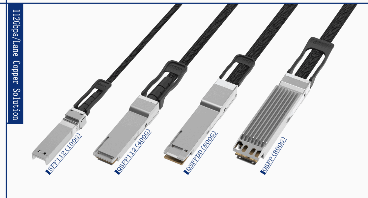
The four high-speed copper cable solutions mentioned above have the following characteristics:
- UsingFiberMall’s self-developed High Speed 112 series high-speed bare wire, which has excellent performance.
- The transmission encoding adopts PAM4-112G technology, supporting up to 40GHz pre-resonance (Suck-out), and is backward compatible with QSFP56 and QSFP28.
- The products comply with the IEEE 802.3ck specification, with a maximum transmission rate of 800Gbps and backward compatibility with 400G products.
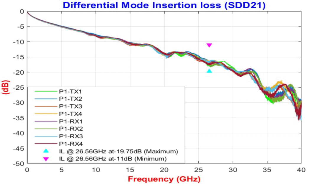
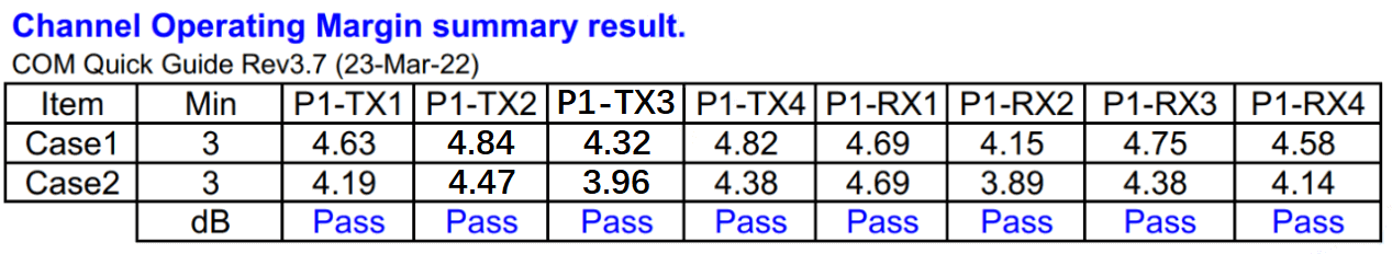
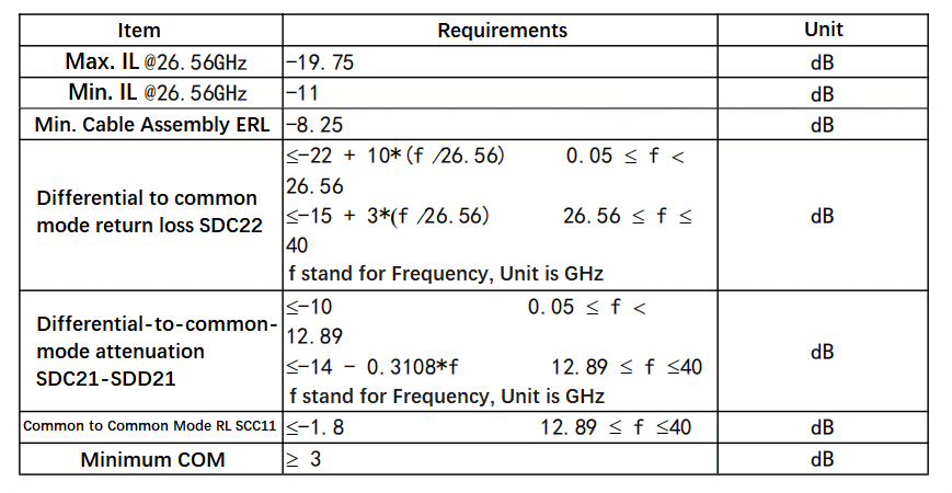
- The insertion loss is less than 19.75dB@26.56GHz, and under the condition of stacking 8 near-end crosstalk and 7 far-end crosstalk, the Channel Operating Margin (COM) is better than 4dB.
The specific DAC technical specifications include:
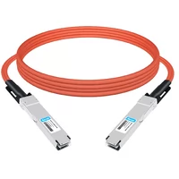
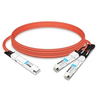
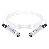
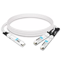
- SFP112 30AWG-1.5M / 28AWG-2.0M
- QSFP112 30AWG-1.5M / 28AWG-2.0M
- QSFP-DD800 30AWG-1.5M / 28AWG-1.5M
- OSFP 800 30AWG-1.5M / 28AWG-2.0M
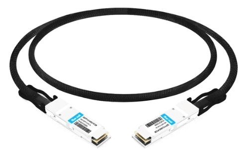
FiberMall QSFP112 26AWG 2M Product Test
112G High-Speed Interconnect Copper Cable Technology
Introduction of High-Speed Copper Cable
High-speed copper cable generally refers to DAC (Direct Attach Cable), which is a direct cable or direct copper cable. It uses silver-plated conduct and foamed insulation cores and adopts wire pair shielding and overall shielding to form a high-speed cable. Compared to optical modules, high-speed copper cables do not have expensive optical lasers and other electronic components, thus significantly saving costs and power consumption in short-distance applications. They serve as low-cost and efficient communication solutions that can replace optical modules.
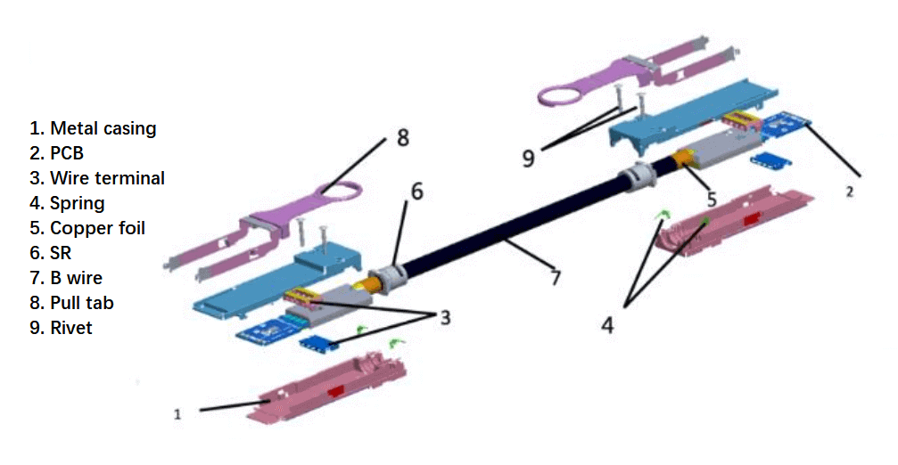
High-Speed DAC Main Components
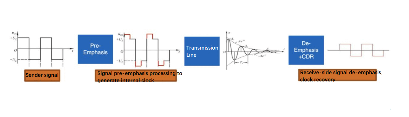
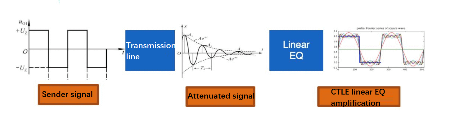
However, with the increase in transmission rates, the overall link imposes stricter requirements on cable loss. Conventional copper cables are no longer able to cover long-distance applications within data center cabinets. This has led to the emergence of active copper cables with linear gain, such as Active Copper Cable (ACC), and even more powerful active copper cables with CDR (Clock Data Recovery) called Active Electric Cable (AEC). The principle of ACC is to add linear compensation (CTLE) to the receiving end of the cable through analog means to compensate for high-loss situations in copper cable applications and meet the link requirements of the system. The principle of AEC is to add CDR or more complex digital signal processing (DSP) algorithms at both ends of the cable. It performs pre-emphasis, de-emphasis, recompilation, and re-driving of the input and output signals, effectively isolating jitter and noise, and achieving higher signal-to-no ratio (SNR) transmission.
ACC Signal Transmission Principle with Linear Gain
AEC (CDR or CDR+DSP Active Copper Cable Signal Transmission Principle)
Application Overview of High-Speed Copper Cable
70% of the internet traffic occurs within data centers, so the interconnection technology within data centers needs to keep up with the increasing data flow. Large-scale internet data centers have been the fastest-growing market in terms of interconnection and the field with the most rapid technological innovation in recent years. In the current popular CLOS data center network architecture, the proportion of links using short-to-long-distance optical modules between the Leaf and Sp layers is approximately one-third of the total number of links between access layer switches and servers. For servers and TOR switches, which account for the majority of interconnection usage, high-speed copper cables (DAC/ACC/AEC) and active optical cables (AOC) can be used for interconnection, covering distances of up to 20 meters. Passive copper cables (DAC) have natural advantages over active optical cables (AOC) in terms of low failure rate, low power consumption, and low cost. With the current requirement for “carbon neutrality,” the Power Usage Effectiveness (PUE) of data centers has become a key metric for measuring data center operational efficiency. In recent years, with the construction and establishment of large-scale/ultra-large-scale data centers, advanced integrated design has significantly increased the power capacity of individual server cabinets, thereby effectively reducing the vertical cabling distance for server access (by adjusting the deployment location of TOR switches). With the deployment of white-box network devices and custom computing nodes, DAC or DAC+ACC solutions have been widely used for server network access links within cabinets, meeting the requirements of high reliability, low cost, and low power consumption for data center construction.
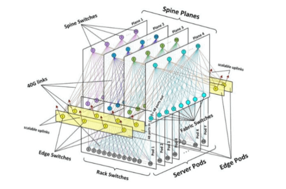
Typical Data Center Network Architecture 1
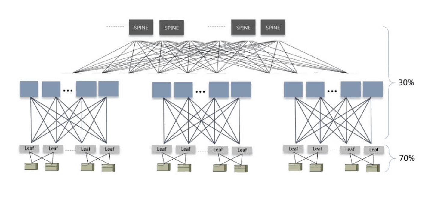
Typical Data Center Network Architecture 2
The diverse range of high-speed copper cable interface types in the 112G series provides a variety of options for different architectural levels and application scenarios. Based on years of market experience and analysis of the design characteristics of various high-speed copper cable interfaces, the mainstream high-speed copper cable interfaces in the 112G PAM4 generation are based on 400G, QSFP-DD 800G, and OSFP 800G. Additionally, there are parallel iterations of SFP112G/SFP-DD112G/DSFP112G.
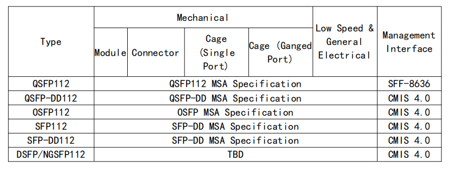
Interface industry-standard reference
High-Speed Copper Cable Design
The highly compatible iterative upgrade of the 112G PAM4 high-speed copper cable solution ensures a stable migration of the new generation of external high-speed copper cable technology. The new solution is designed based on the requirements of the existing product family, combined with the existing structural characteristics for upgrading and evolution. While improving the speed, it also ensures the continuity of management interfaces and pin definitions.
Copper Cable Structural Design
Based on different application environments, various forms of OSFP and QSFP-DD products have been derived. The design of multiple forms is based on the consideration of the module’s heat dissipation requirements. Considering that the power consumption of passive copper cables is very low (milliwatts level) and taking into account the normalization of product forms promotes the healthy development of products and the market, QSFP-DD Type1 and OSFP Open Top are generally preferred models for passive copper cables (taking QSFP112G as an example).
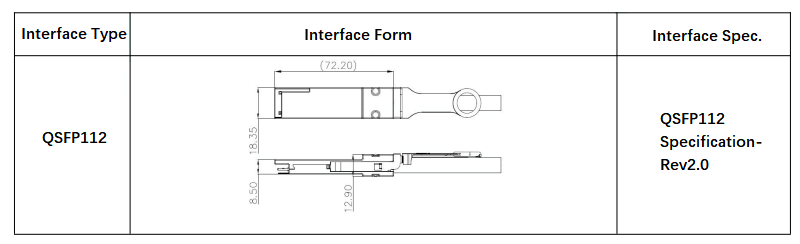
QSFP112 Dimension Reference
Copper Circuit Design
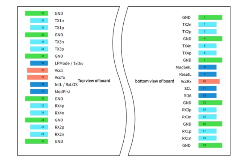
QSFP112 Pin definition
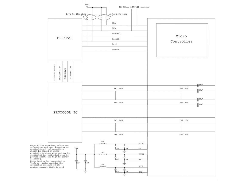
Example QSFP112 Host Board Schematic for Passive Copper Cables
Management Interface Standard
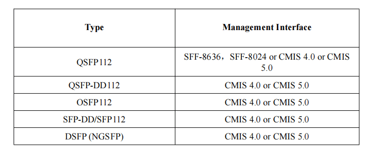
EEPROM Map Reference Specifications
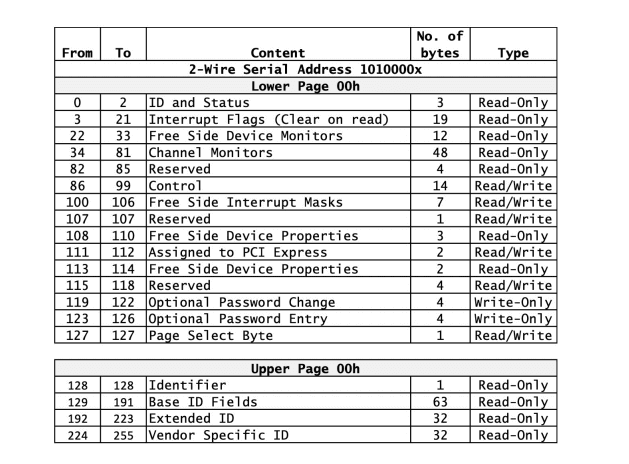
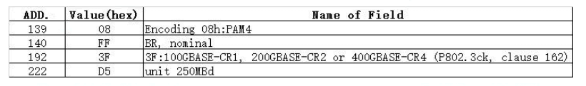
For the above, refer to SFF-8636 Management Interface for Cabled Environments Rev 2.9.
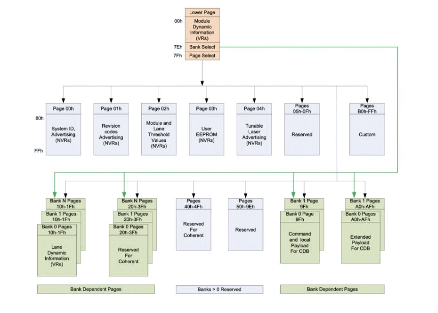
CMIS Module Memory Map
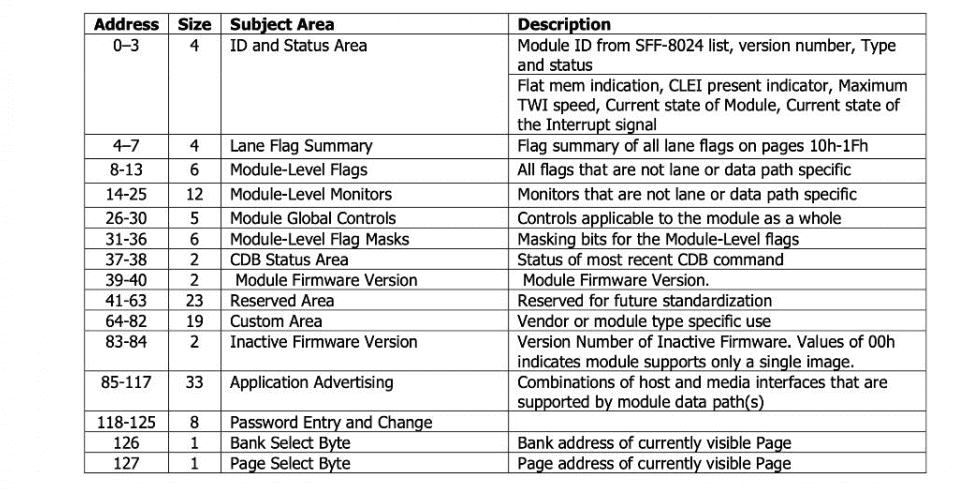
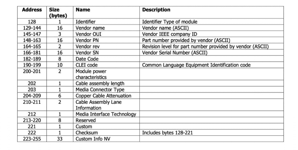
For the above, refer to Common Management Interface Specification Rev 4.0.
Testing and Certification of High-speed Copper Cables
In order to ensure the unity and standardization of the certification process of high-speed cables, based on the premise of EIA-364 test standard requirements, combined with the design and application characteristics of external high-speed copper cables, the electrical, mechanical, and environmental reliability requirements.
- Signal Integrity Test Item Requirements and Methods
The following items are the test data of TP1-TP4, including MCB PCB alignment and connector, as shown in the following figure:
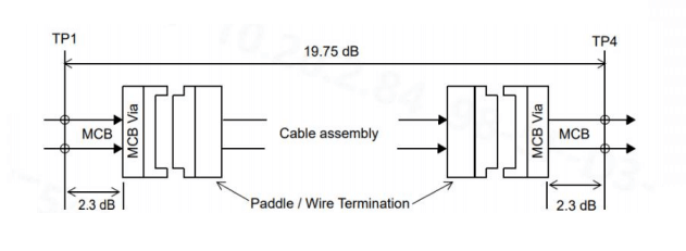
Test specifications:
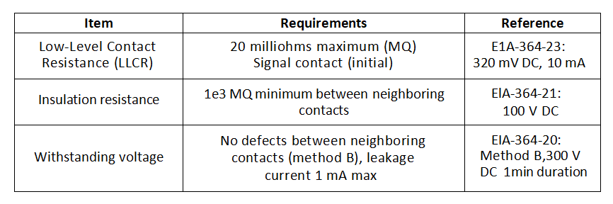
- Electrical Reliability Test Requirements
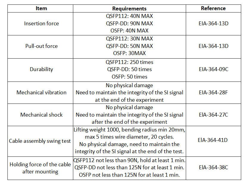
- Mechanical Reliability Test Requirements
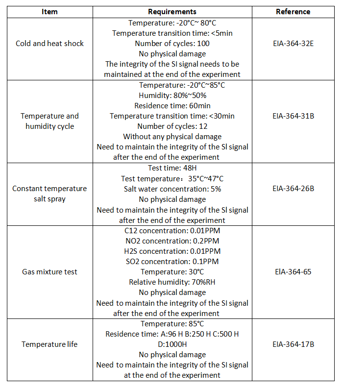
- Environmental reliability test requirements
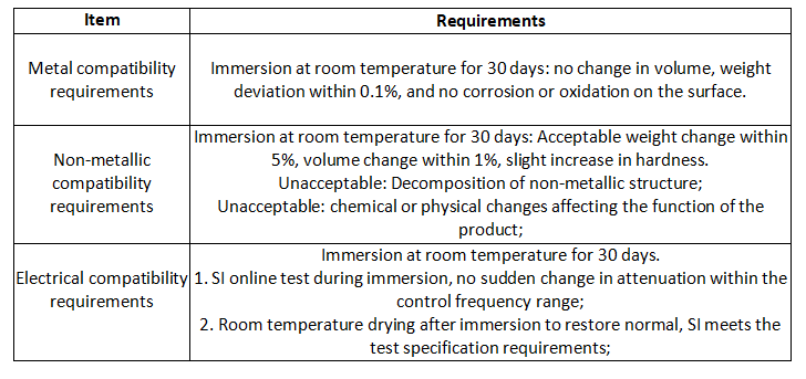
- Liquid-cooled compatibility test requirements
Related Products:
-
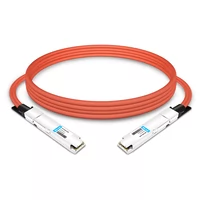
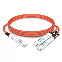
 NVIDIA MCA4J80-N003-FLT Compatible 3m (10ft) 800G Twin-port 2x400G OSFP to 2x400G OSFP InfiniBand NDR Active Copper Cable, Flat top on one end and Flat top on the other
$600.00
NVIDIA MCA4J80-N003-FLT Compatible 3m (10ft) 800G Twin-port 2x400G OSFP to 2x400G OSFP InfiniBand NDR Active Copper Cable, Flat top on one end and Flat top on the other
$600.00
-
NVIDIA MCA7J65-N004 Compatible 4m (13ft) 800G Twin-port OSFP to 2x400G QSFP112 InfiniBand NDR Breakout Active Copper Cable
$800.00
-
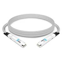
NVIDIA MCP4Y10-N002-FLT Compatible 2m (7ft) 800G Twin-port 2x400G OSFP to 2x400G OSFP InfiniBand NDR Passive DAC, Flat top on one end and Flat top on the other
$300.00
-
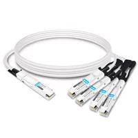
NVIDIA MCP7Y10-N001 Compatible 1m (3ft) 800G InfiniBand NDR Twin-port OSFP to 2x400G QSFP112 Breakout DAC
$155.00
-
NVIDIA MCP7Y40-N001 Compatible 1m (3ft) 800G InfiniBand NDR Twin-port OSFP to 4x200G QSFP112 Breakout DAC
$165.00
-
NVIDIA MCA4J80-N003 Compatible 800G Twin-port 2x400G OSFP to 2x400G OSFP InfiniBand NDR Active Copper Cable
$600.00
-
NVIDIA MCP4Y10-N00A Compatible 0.5m (1.6ft) 800G Twin-port 2x400G OSFP to 2x400G OSFP InfiniBand NDR Passive Direct Attach Copper Cable
$105.00
-
NVIDIA MCA7J60-N004 Compatible 4m (13ft) 800G Twin-port OSFP to 2x400G OSFP InfiniBand NDR Breakout Active Copper Cable
$800.00
-
QSFP112-400G-LR4 400G QSFP112 LR4 PAM4 CWDM 10km Duplex LC SMF FEC Optical Transceiver Module
$1500.00
-
QSFP112-400G-FR4 400G QSFP112 FR4 PAM4 CWDM 2km Duplex LC SMF FEC Optical Transceiver Module
$750.00
-
QSFP112-400G-FR1 4x100G QSFP112 FR1 PAM4 1310nm 2km MTP/MPO-12 SMF FEC Optical Transceiver Module
$1200.00
-
QSFP112-400G-SR4 400G QSFP112 SR4 PAM4 850nm 100m MTP/MPO-12 OM3 FEC Optical Transceiver Module
$450.00
-
QSFP-DD-800G-SR8 800G SR8 QSFP-DD 850nm 100m OM4 MMF MPO-16 Optical Transceiver Module
$850.00
-
QSFP-DD-800G-DR8 800G-DR8 QSFP-DD PAM4 1310nm 500m DOM MTP/MPO-16 SMF Optical Transceiver Module
$1300.00
-
QSFP-DD-800G-LR8 QSFP-DD 8x100G LR PAM4 1310nm 10km MPO-16 SMF FEC Optical Transceiver Module
$1600.00
-
QSFP-DD-800G-FR8L QSFP-DD 800G FR8 PAM4 CWDM8 2km DOM Duplex LC SMF Optical Transceiver Module
$3000.00
-
OSFP-800G-SR8 OSFP 8x100G SR8 PAM4 850nm MTP/MPO-16 100m OM4 MMF FEC Optical Transceiver Module
$650.00
-
OSFP-800G-2FR4 OSFP 2x400G FR4 PAM4 CWDM4 2km DOM Dual CS SMF Optical Transceiver Module
$1500.00
-
OSFP-800G-LR8 OSFP 8x100G LR PAM4 1310nm MPO-16 10km SMF Optical Transceiver Module
$1800.00
-
OSFP-800G-2LR4 OSFP 2x400G LR4 PAM4 CWDM4 Dual CS 10km SMF Optical Transceiver Module
$2000.00