In recent years, thanks to the acceleration of broadband networks, the application of 10G networks has become increasingly extensive. The parameters we need to know about 10G SFP+ optical modules, the basic transmission device of 10G networks, are as follows:
1. Center wavelength (nm): there are three main types:
1) 850nm (multi-mode, with low cost but short transmission distance, and the maximum transmission distance is 500M);
2) 1310nm (single-mode, with large loss but small dispersion during transmission, generally used for transmission within 40KM);
3) 1550nm (single-mode, small loss but large dispersion during transmission, generally used for long-distance transmission over 40KM, up to 120KM can be directly transmitted without relay);
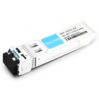
FiberMall 10G SFP+ ER
2. Transmission rate: refers to the number of bits of data transmitted per second, in bps, frequently-used rates include: 155Mbps, 622Mbps, 1.25Gbps, 2.5Gbps, 4Gbps, 8Gbps, 10Gbps, etc. 155M optical module is also called FE (100M) optical module, 1.25G optical module is also called GE (1000M) optical module, and 10G SFP+ optical module is the most widely used in optical transmission equipment.
3. Transmission distance: refers to the distance that optical signals can be directly transmitted without repeater amplification, in units of kilometers. These are the common specifications: multi-mode 550m, single-mode 15km, 40km, 80km, 120km, and so on.
4. Types of laser: The laser is the core device in the optical module. It injects current into the semiconductor material and emits laser light through the photon oscillation and gain of the resonator. At present, the most commonly used lasers are FP and DFB lasers. The difference between them is the semiconductor material and cavity structure. The price of DFB lasers is much more expensive than that of FP lasers. Optical modules with a transmission distance of less than 40KM generally use FP lasers; optical modules with a transmission distance of ≥40KM generally use DFB lasers;
5. Loss and dispersion: Loss is the loss of light energy due to absorption, scattering, and leakage of the medium when light is transmitted in the optical fiber. This part of the energy is dissipated at a certain rate with the increase of the transmission distance. Dispersion is mainly caused by the fact that electromagnetic waves of different wavelengths travel in the same medium at different speeds. This results in different wavelength components of the optical signal arriving at the receiving end at different times due to the accumulation of transmission distances, leading to pulse broadening and the inability to distinguish the signal value.
These two parameters mainly affect the transmission distance of the optical module. In the actual application, the link loss of the 1310nm optical module is generally calculated at 0.35dBm/km, and the link loss of the 1550nm optical module is generally calculated at 0.20dBm/km. The calculation of the dispersion value is very complex, generally for reference only;
6. Transmitting optical power and receiving sensitivity: Transmitting optical power refers to the output optical power of the light source at the transmitting end of the optical module. Receiving sensitivity refers to the minimum received optical power of the optical module at a certain rate and bit error rate. The units of these two parameters are dBm (the logarithmic form of the power unit, MW, 1mw is converted to 0dBm), which is mainly used to define the transmission distance of the product. The optical transmit power and receiving sensitivity of optical modules with different wavelengths, transmission rates, and transmission distances will be different.
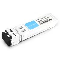
FiberMall 10G SFP+ SR
7. The service life of the optical module: the international unified standard, 7Х24 hours of uninterrupted work for 50,000 hours (equivalent to 5 years);
8. Optical fiber interface: SFP optical modules are all with LC interfaces, GBIC optical modules are with SC interfaces, and other interfaces include FC and ST;
9. Environmental parameters: working temperature: 0~+70℃; storage temperature: -45~+80℃; working voltage: 3.3V; working level: TTL.
| Product Specifications | Transmission rate | Fiber Mode | Interface Specifications (dBm) | |
|---|---|---|---|---|
| Transmitting optical power | Receiving sensitivity | |||
| XFP/SFP+/MMF 850nm/300m | 10Gbps | MMF | -7.3~-1.08dBm | ≤-11.1dBm |
| XFP/SFP+/SMF 1310nm/10km | SMF | -8.2~+0.5dBm | ≤-12.6dBm | |
| XFP/SFP+/SMF 1550nm/40km | -1.0~+2dBm | ≤-14.1dBm | ||
| XFP/SFP+/SMF 1550nm/80km | 0~4dBm | ≤-24dBm | ||
As of March 19, 2022, there are 356 commercial LTE networks, and the entire TD industry chain is very mature.
The modules in LTE construction mainly include 6G and 10G SFP+ optical modules. The market demand and mature industry chain make the optical module technology continue to innovate. At the same time, the cost pressure is transferred from operators to optical module manufacturers through equipment manufacturers. Regarding the receiving technology of the LTE10G optical module, there are currently two solutions: a high return loss receiving solution and a conventional receiving solution. The difference between the two solutions is mainly reflected in the optical return loss design of the receiving device in the module.
For the conventional receiving scheme, after the LC connector is inserted into the receiving device, there is an air gap between its flat end face and the PIN die in the device. Most of the light transmitted in the optical fiber is perpendicular to the flat end face, when the light reflects, the reflected light will all travel back to the core. The return reflectivity can be calculated by Rf=(nf-1)2/(nf+1)2, nf is the refractive index of the fiber material, nf=1.47, and Rf=3.6% (-14.4dB).
Another study believes that after the fiber end face is ground and polished, a metamorphic thin layer will be produced on the fiber end face, and its refractive index is about 1.6, which is higher than the refractive index of the fiber core. At this time, Rf=5.3% (-12.7dB ), that is, the return loss is -12.7dB, which is very close to the lower limit standard of 10G Ethernet(-12dB), with almost no margin.
Compared with the conventional receiving scheme, the high return loss receiving scheme adds an angled ceramic pin between the LC connector and the PIN die, as shown in Figure 2 below. The beveled end face of the pin is not at the right angle to the core axis of the fiber. Although there is an air gap, the propagation angle of the emitted light reflected by the slanted end face is less than the critical angle of total reflection. Therefore, the light reflected from the slanted end face of the pin, will not propagate in the fiber core, but all dissipate through the cladding and eventually leak out. Taking the 8° inclined pin as an example, according to the measured return loss statistics, it is generally better than -27dB. Therefore, in terms of optical return loss, the conventional receiving scheme is far inferior to the high return loss receiving scheme.
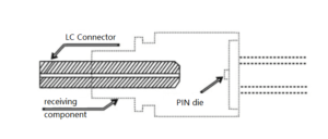
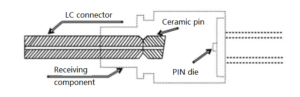
Schematic diagram of the conventional receiving device structure Schematic diagram of the structure of the high return loss receiving device
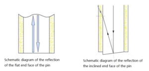
Schematic diagram of the reflection of the flat/inclined end face of the pin
Optical return loss is defined as the ratio of the reflected optical power to the incident optical power. The worse the return loss, the stronger the optical reflection in the optical fiber link. In the optical fiber transmission system, the connector, fiber end face, optical interface, and detector surface will all cause Fresnel reflections. The effects of these retro-reflections on the system include:
1) Weaken the transmitted optical signal
2) Interfere with incident optical signal
3) Reduce the signal-to-noise ratio in digital transmission systems.
Retro-reflected light also returns to the emitting light source, whose effects on the light source include:
1) Cause the central wavelength of the emitted light source to fluctuate:
2) cause the light intensity fluctuation of the emitted light source;
3) Permanently damage the light source.
Even if it is an FP light source, although the retro-reflection has little effect on the spectral characteristics, the retro-reflected light is amplified by the active area after entering the resonant cavity of the light source and joins the mainstream, causing fluctuations in light intensity. Fluctuations in light intensity result in RIN, which is noise associated with the transmitter rather than the receiver.RIN will limit the maximum possible signal-to-noise ratio on the fiber link, which in turn affects receiver sensitivity. Moreover, RIN is essentially a broadband noise, which reflects the influence of the intensity fluctuation of the light source and the system on the electrical noise at the receiving end, compared to the influence of signal power. The formula is expressed as RIN=<P>2 /(P2*BW).
<ΔP> is the average noise power, P is the average optical power, and BW is the bandwidth of the receiver and system link.
It can be seen that the higher the system rate, the wider the link noise bandwidth, the greater the noise power, the lower the signal-to-noise ratio, and the higher the bit error rate. Therefore, for 10G LTE optical modules, to ensure the reliability of the optical transmission system and the stability of the spectrum and power of the emitted light source, it is necessary to design the receiving device with high return loss to reduce the link reflection. Although the module with a conventional receiving solution can use the optical isolator solution at the transmitting end to protect the light source, the reflection caused by the return loss still has an impact on the system. And the price of the isolator is much higher than that of the fiber optic pin in the high return loss solution.
Related Products:
-
 Cisco DS-SFP-FC10G-SW Compatible 10G SFP+ SR 850nm 300m LC MMF DDM Transceiver Module
$12.00
Cisco DS-SFP-FC10G-SW Compatible 10G SFP+ SR 850nm 300m LC MMF DDM Transceiver Module
$12.00
-
SFP-10G85-SRI 10G SFP+ SR 850nm 300m LC MMF DDM Industrial High Temperature Transceiver Module
$13.00
-
Cisco SFP-10G-LR-S Compatible 10G SFP+ LR 1310nm 10km DDM Duplex LC SMF Transceiver Module
$18.00
-
DELL 407-BBZV Compatible 10G SFP+ LR 1310nm 10km LC SMF DDM Industrial High Temperature Transceiver Module
$20.00
-
Arista Networks SFP-10G-ER40 Compatible 10G SFP+ ER 1310nm 40km LC SMF DDM Transceiver Module
$25.00
-
Cisco SFP-10G-ZR-S Compatible 10G SFP+ ZR 1550nm 80km LC SMF DDM Transceiver Module
$150.00
-
Cisco SFP-10G-ZR100 Compatible 10G SFP+ ZR 1550nm 100km LC SMF DDM Transceiver Module
$280.00
-
SFP-10G55-ZR120 10G SFP+ ZR 1550nm 120km LC SMF DDM Transceiver Module
$400.00