When we read an article, if there is a typographical error, say two words in the wrong order, there will be no difficulty for us to understand the original text. But if there are too many spelling mistakes, it will be difficult for readers to understand the article. At this time, information cannot be obtained correctly and efficiently.
FEC (Forward Error Correction) works on a similar principle. Signals are encoded as “0” and “1” for transmission, with inevitable degradation and error codes. When this level of error is within the range of FEC’s error correction capability, the system can achieve error-free reception, and thus without the need for re-transmission.
Hamming Code, probably the first form of FEC, was first invented by Richard Hamming in 1950. While working at Bell Labs, he was annoyed by the frequent errors in punch cards (which were used to record and transmit data at the time), so he devised a coding method to identify and correct errors, thus avoiding the need to copy and resend cards.
The two essential development directions of fiber optic communication are to increase the transmission rate and to extend the transmission distance. As the transmission rate increases, more factors limit the transmission distance during signal transmission. Chromatic dispersion, nonlinear effects, polarization mode dispersion, and other factors affect the simultaneous enhancement of the two directions. Industry experts have proposed the Forward Error Correction function to reduce the impact of these adverse factors.
In optical transmission systems, the central role of FEC is to reduce the tolerance of the OSNR of the system. If we compare the optical transmission system to the process of reading, FEC improves the readers’ comprehension, enriches their discriminating experience, and to some extent allows more errors in the article.
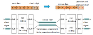
Figure1: the schematic diagram of the FEC function
Therefore, we define FEC (Forward Error Correction) as an ability that ensures that the communication system can still achieve error-free transmission under the influence of noise and other impairments. Essentially, FEC is a process of encoding and decoding, and the result of the algorithm is sent as additional information along with the data from the transmitter. By repeating the same algorithm at the far end, the receiver can detect single-bit-level errors and correct them (correctable errors) without re-transmitting the data.
To measure this capability, it is necessary to focus on four quantities of FEC: pre-correction BER tolerance, coding gain (CG), overhead (OH), and net coding gain (NCG). Let’s take a look at the definition of NCG coding gain: it defines the difference between the Q value corresponding to a certain level of BER (for example, 1 × 10-15) and the Q (dB) value corresponding to the pre-correction BER tolerance.
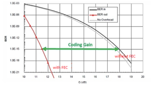
Figure 2: the coding gain between a certain level of BEC with FEC and without FEC
NCG can be compared to the ability difference to correct and receive the right information between a novice and an expert. Generally speaking, there are two types of FEC technologies: in-band FEC and out-of-band FEC.
- In-band FEC: Defined by the ITU-T G.707 standard. It uses an overhead byte of the SDH frame to carry the FEC symbol and is mainly used in the SDH system.
- Out-of-band FEC: Supported by the ITU-T G.975/709 standard. G.975 is recommended for the FEC of the submarine optical cable system, using RS (255, 239), and G.709 is modified according to the FEC code of G.975.
In the DWDM/OTN system, we mainly use out-of-band FEC technology. In G.709, Reed Solomon FEC (RS-FEC) is defined for the OTN system, which is located in the FEC overhead of the OTUk layer, and its location is shown in the following figure.
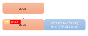
Figure3:the location of the RS-FEC in G.709
At present, FEC has developed for many generations.
- The first generation of FEC mainly uses cyclic codes or algebraic codes, such as RS (255, 239) codes defined by ITU-T G.975, which is often called standard FEC.
- The second generation of FEC mainly uses cascade codes to construct FEC, such as RS+RS or RS+BCH. There are two types of FEC, Enhanced FEC (EFEC) and Addition FEC (AFEC).
- The third-generation FEC adopts soft-decision or iterative methods, such as Block Turbo Code and LDPC low-density parity-check code.
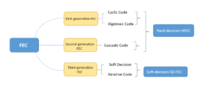
Figure4: The three generations of FEC
In the first and second-generation FEC technologies, decoding usually uses only the algebraic structure of the code. The binary sequence is supplied to the decoder by the demodulator, that is, the demodulator only performs 0, 1 decision on the received sequence. This decoding method is called Hard-Decision (HD-FEC). Different kinds of hard decision FEC are compared as follows:
| Coding | Encoding Algorithm | Coding Gain | Line Speed | Standard |
|---|---|---|---|---|
| Out-of-band FEC | RS(255,239) | 5~7dB | 10.7Gbps | G.709 |
| Enhanced-FEC | RS(255,238) RS(245,210) | 7~9dB | 12.5Gbps | No |
| Advanced-FEC | RS(255,238) BCH(900,860) BCH(500,491) | 7~9dB | 10.7Gbps. | G.709 |
Table one: Comparisons of three different kinds of hard decision FEC
The Soft-Decision used in the third generation of FEC (SD-FEC) is a probabilistic decoding method. It performs multi-bit quantization on the sampled voltage output by the demodulator, and then sends it to the decoder to decode the algebraic structure of the code.
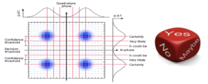
Figure5: Schematic diagram of soft decision technology
As shown in the figure above, the hard decision only uses one threshold to quantize one bit, while the soft decision uses multiple thresholds to quantize the recovered symbols, getting one-bit information plus several-bit probability (confidence) information. It is equivalent to adding Maybe between YES and NO. With the same overhead ratio, SD-FEC’s NCG gain is 1-1.5dB higher than that of hard-decision HFEC.
| Overhead | HD | SD | Additional NCG (HD>SD) |
|---|---|---|---|
| 0.07 | 10.00dB | 11.10dB | 1.10dB |
| 0.15 | 10.95dB | 12.20dB | 1.25dB |
| 0.25 | 11.60dB | 12.90dB | 1.30dB |
Table two: comparisons of NCG of SD-FEC and HD-FEC
At present, SD-FEC or a hybrid encoding method such as SD-FEC and EFEC/HFEC is mostly used in 100G and beyond 100G wavelength division systems. Taking the definition of LDPC by the LOFC conference as an example, its overhead and NCG are shown in the following table.
| FEC type | Overhead OH | NCG |
|---|---|---|
| EFEC+LDPC | 0.205 | 10.8dB |
| LDPC | 0.2 | 11.3dB |
| LDPC+CC | 0.11 | 10.2dB |
| LDPC+CC | 0.2 | 11.5dB |
| BCH+LDPC | 0.255 | 12.0dB |
Table three: overheads and NCGs of different FEC
From the above table, we seem to draw a rule: the higher the overhead used by FEC, the higher the coding gain.
FEC is suitable for high-speed communication (25G, 40G, and 100G, especially 40G and 100G). The optical signal is degraded due to other factors during transmission, resulting in misjudgment at the receiving end. It may misjudge the “1” signal as a “0” signal, or the “0” signal as a “1” signal. The FEC function forms the information code into a code with error correction capability via the channel encoder at the transmitting end, and the channel decoder at the receiving end decodes the received code. The decoder will locate and correct the error to improve the quality of the signal if the number of errors generated in the transmission is within the error correction capability (discontinuous errors).
100G QSFP28 optical module and FEC function
The FEC function will inevitably cause some packet delays in the process of correcting bit errors, so not all 100G QSFP28 optical modules need to enable this function. According to the IEEE standard protocol, when using the 100G QSFP28 LR4 optical module, it is not recommended to enable FEC, and it is recommended for other optical modules.
100G QSFP28 optical modules of different companies are different in some aspects. The following table shows whether it is recommended to enable the FEC function when using the FiberMall 100G QSFP28 optical module.
| Model number | Product description | With FEC |
|---|---|---|
| QSFP28-100G-SR4 | 100G QSFP28 SR4 850nm 100m MTP/MPO MMF DDM Transceiver Module | NO |
| QSFP28-100G-LR4 | 100G QSFP28 LR4 1310nm (LAN WDM) 10km LC SMF DDM Transceiver Module | NO |
| QSFP28-100G-PSM4 | 100G QSFP28 PSM4 1310nm 500m MTP/MPO SMF DDM Transceiver Module | NO |
| QSFP28-100G-IR4 | 100G QSFP28 IR4 1310nm (CWDM4) 2km LC SMF DDM Transceiver Module | Yes |
| QSFP28-100G-4WDM-10 | 100G QSFP28 4WDM 10km LC SMF DDM Transceiver Module | Yes |
| QSFP28-100G-ER4 | 100G QSFP28 ER4 Lite 1310nm (LAN WDM) 40km LC SMF DDM Transceiver Module | Yes |
Table four: When to use FEC in FiberMall 100G QSFP28
Consistency of FEC functions at both ends of the link
The FEC function of an interface is a part of auto-negotiation. When auto-negotiation is enabled on an interface, the FEC function is determined by the two ends of the link through negotiation. If one end has the FEC function enabled, the other end must also enable the FEC function.
Stacking and FEC function
If the interface has been configured as a stack physical member port, the FEC command is not supported. Conversely, the interface that has been configured with the FEC command cannot be configured as a stack physical member port.
Related Products:
-
 Cisco QSFP-100G-SR4-S Compatible 100G QSFP28 SR4 850nm 100m MTP/MPO MMF DDM Transceiver Module
$40.00
Cisco QSFP-100G-SR4-S Compatible 100G QSFP28 SR4 850nm 100m MTP/MPO MMF DDM Transceiver Module
$40.00
-
QSFP28-100G-LR4 100G QSFP28 LR4 1310nm (LAN WDM) 10km LC SMF DDM Transceiver Module
$285.00
-
Cisco QSFP-100G-PSM4-S Compatible 100G QSFP28 PSM4 1310nm 500m MTP/MPO SMF DDM Transceiver Module
$180.00
-
Cisco QSFP-100G-SM-SR Compatible 100G QSFP28 CWDM4 Lite 1310nm 2km LC SMF DDM Transceiver Module
$110.00
-
Cisco QSFP-100G-4WDM-10-S Compatible 100G QSFP28 4WDM 10km LC SMF DDM Transceiver Module
$200.00
-
Cisco QSFP-100G-ER4L-S Compatible 100G QSFP28 ER4 Lite1310nm (LAN WDM) 40km with FEC,30km without FEC LC SMF DDM Transceiver Module
$800.00