The function of the optical module is to carry out the photoelectric and electro-optic conversion. The transmitter converts the electrical signal into an optical signal, which is transmitted through optical fiber, and then the receiver converts the optical signal into an electrical signal.
The following is a block diagram of how an optical module works:
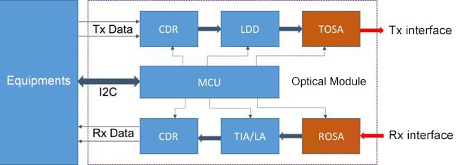
The left side of the diagram shows a device that applies an optical module, such as a switch. The device inputs the signal to the optical module, which converts the electrical signal into the optical signal and sends it out. Receiving is the inverse process of sending.
The Main Components of an Optical Module Include:
1. TOSA (Transmitter Optical Sub-Assembly)
TOSA is used to realize the electro-optical conversion in the optical module, the built-in devices include optical laser, MPD, TEC, isolator, MUX, coupling lens, and so on. It is available in TO-CAN, Gold-BOX, COC (chip on chip), COB (chip on board), and other packaging forms. For the optical module applied in the data center, TEC, MPD, and isolator are not necessary items to save cost. Mux is also only used in optical modules that require WDM. In addition, the LDD of some optical modules is also packaged in TOSA.
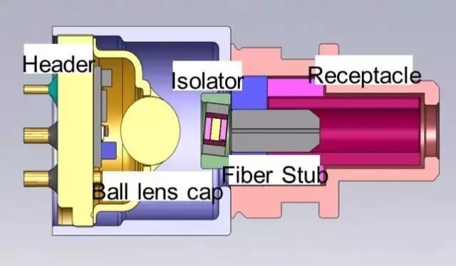
TOSA block diagram
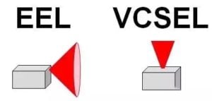
The core of TOSA is the optical laser, which can be divided into two types:
① EEL (Edge Emitter Laser): refers to the edge-emitting laser with a wavelength of 1310nm or 1550nm.
② VCSEL (Vertical Cavity Surface Emitting Laser): refers to the vertical surface cavity laser with a wavelength of 850nm.
2. ROSA (Receiver Optical Sub Assembly)
The main function of ROSA is to convert optical signals to electrical signals. The built-in devices include PD / APD, demux, coupling components, etc. And the package type is generally the same as TOSA. Moreover, PD is used for short and medium-range optical modules, and APD is mainly used for long-range optical modules.
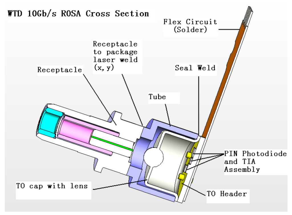
ROSA block diagram
3. LDD (Laser Diode Driver)
LDD is a driving device in the optical module. It can convert the signal output from CDR into a corresponding modulation signal, which drives the laser to send out the optical signal. Since the optical laser itself is a current-sensitive device, we need LDD to convert the digital voltage signal to the current signal. Different types of LDD chips need to be selected for different types of lasers. Normally, short-range multimode optical modules, such as 100G SR4, LDD, and CDR are integrated on the same chip.
4. CDR (Clock and Data Recovery)
CDR has two main roles: the first is to provide the clock signal for each circuit of the receiver; the second is to judge the received signal, which is convenient for data signal recovery and subsequent processing. The biggest function of CDR is to make the signal at the receiving end consistent with that at the transmitting end. Generally, the optical modules that will use CDR are mostly high-speed and long-distance optical modules, such as 10G SFP+ ER or 10G SFP+ ZR.
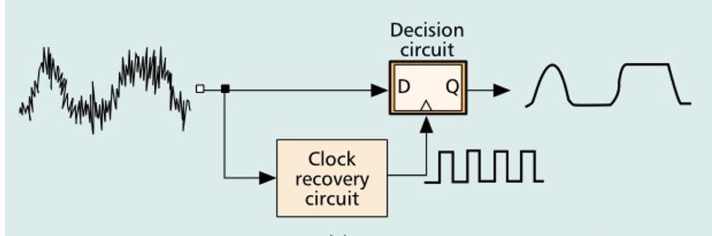
CDR operation diagram
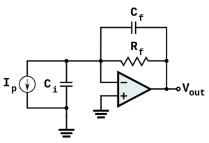
5. TIA(Trans-Impedance Amplifier)
TIA is a type of amplifier, located at the front of the detector in the optical module. The detector converts the optical signal into a current signal, and the TIA processes the current signal into a voltage signal of a certain amplitude, which we can simply understand as a large resistor.
6. LA(Limiting Amplifier)
The output amplitude of the TIA changes as the received optical power changes, while the function of LA is to process the changing output amplitude into an equal-amplitude electrical signal, thus providing a stable voltage signal to the CDR. In high-speed modules, LA is usually integrated with TIA or CDR.
7. MCU(Micro-Controller Unit)
The MCU is responsible for the operation of the software, the monitoring of the DDM, and some specific functions. the DDM function mainly monitors the five analog signals of temperature, Vcc voltage, Bias current, Rx power, and Tx power in real-time, and judges the working condition of the optical module by these parameters, which facilitates the maintenance of the optical communication link.
How do optical signals transmit information in the optical network?
Summary
The optical module is composed of many devices, including optoelectronic devices, functional circuits, and optical interfaces. Optoelectronics includes both transmitting and receiving parts, among which the laser chip and detector chip are collectively called the optical communication chip, which is the core part of the optical module. Understanding the basic structure of optical modules is the basis for mastering their working principle of them and distinguishing their package types.
Related Products:
-
 SFP-10G85-SR 10G SFP+ SR 850nm 300m LC MMF DDM Transceiver Module
$12.00
SFP-10G85-SR 10G SFP+ SR 850nm 300m LC MMF DDM Transceiver Module
$12.00
-
SFP-10G31-LR 10G SFP+ LR 1310nm 10km LC SMF DDM Transceiver Module
$18.00
-
SFP-10G31-ER 10G SFP+ ER 1310nm 40km LC SMF DDM Transceiver Module
$25.00
-
SFP-10G55-ZR 10G SFP+ ZR 1550nm 80km LC SMF DDM Transceiver Module
$150.00
-
QSFP28-100G-SR4 100G QSFP28 SR4 850nm 100m MTP/MPO MMF DDM Transceiver Module
$40.00
-
QSFP28-100G-LR4 100G QSFP28 LR4 1310nm (LAN WDM) 10km LC SMF DDM Transceiver Module
$285.00