There are many optical module manufacturers, far more than most people can imagine. 80% of them are very small, and some of them are even small workshops. Therefore, the quality of optical modules circulating on the market varies. In the purchase of optical transceiver modules, especially third-party optical modules, be sure to determine the compatibility of optical modules. Otherwise, you will encounter a variety of problems, such as the more common port not UP, link oscillation, a large number of CRC error packets or packet loss, optical module burn, optical module running down, or network card temperature rises, the optical module began to lose packets, a module plugged into the vicinity of a number of other ports are down, one end is UP the other end is down, and so on.
What are the differences between optical transceiver modules from different manufacturers?
The standard for optical modules is very uniform, so theoretically there should be little difference between module manufacturers. However, the reality is that there are a variety of compatibility issues between different modules and different devices. Even the same manufacturer with the same module model in the same device will have differences. Simply put, it is the difference between the quality of engineering and the quality of supply.
- PCB quality: the quality of the selected capacitor resistor, the length and width of the gold finger, the quality of the solder, and even the quality of the glue all affect the quality of the product. For example, there is jitter in the voltage and current, and problems arise when the temperature rises.
- Differences in coupling processes:such as COB coupling mode and SMD coupling mode. Each manufacturer’s choice is different, and even the same manufacturer’s choice of different products is different. They will lead to differences in cost, heat dissipation, and high-temperature resistance.
- Differences in production and test equipment: the number of equipment, the richness of the variety, the degree of automation, the richness of third-party equipment such as switches/server NICs, will lead to differences in yield and compatibility.
What tests have FiberMall optical transceiver modules passed?
- Average Output Optical Power Detection
The average output optical power is an important parameter of an optical module, which directly affects the communication quality. The FiberMall optical module uses an optical power meter to measure the optical power output of the optical transceiver, so as to test the average optical power output.
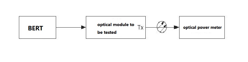
Average Output Optical Power Test Configuration
- Extinction Ratio and Optical Modulation Amplitude (OMA) Test
The extinction ratio is one of the parameters used to measure the quality of optical transceiver modules. It can be detected whether the laser works in the best bias point and the best modulation efficiency range by testing. In addition, the optical modulation amplitude (OMA) is also a measure of the power difference between the laser on and off. The two tests of FiberMall optical modules were tested by mainstream optical oscilloscopes, and both passed the tests.
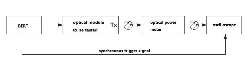
Extinction Ratio Test Configuration
- Bit Error Rate and Receiving Sensitivity Test
Bit error rate (BER) is one of the parameters to measure the ability of an optical module to transmit symbols correctly. The bit error rate test of FiberMall optical module receives the optical signal with a pseudo-random signal output from the tested optical module through the standard receiving tube test unit. At the same time, the standard receiving tube test unit is used for demodulation and comparison to complete the bit error rate test.
Receiving sensitivity is one of the key parameters to evaluate the performance of optical transceiver devices. The receiving sensitivity of FiberMall optical module is tested by using a programmable optical attenuator to attenuate the signal power so that the receiving end of the optical transceiver module receives signals with different power. Finally, the receiving sensitivity test is completed by comparing the bit error rate under different optical power with the bit error meter.
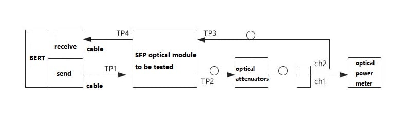
Receiving Sensitivity Test Configuration
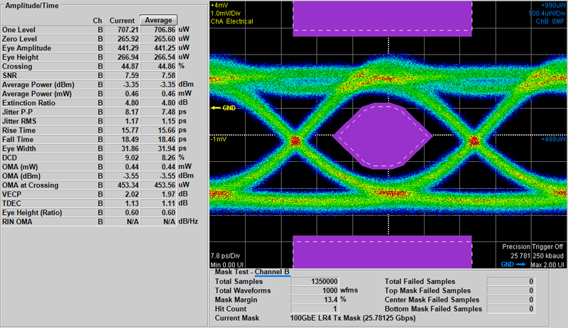
- Eye Diagram Testing
Eye diagram testing and adjustment is an important stage to ensure that the optical module gets the best signal. The digital signal quality of the optical transceiver can be seen from the eye diagram test results. The performance of the optical module is judged by carefully observing the eye height, eye width, jitter, and duty cycle of the eye diagram. The larger the eye indicates the smaller the inter-code crosstalk, the better the performance of the optical transceiver. FiberMall optical module eye diagram test results are very good, as shown in the figure below.
- Wavelength Test
Since the optical transceiver modules used on both ends of the device must emit the same wavelength to establish communication. Therefore, before shipment, FiberMall optical module wavelengths are tested to ensure that they are within the deviation range. In addition, FiberMall optical transceiver modules were subjected to very low-temperature tests, high and low-temperature cycle test,s and constant humidity and heat test, all of which worked properly.
- Aging Test
FiberMall optical modules use optical aging chamber to simulate extreme conditions for optical transceiver testing, to verify whether the performance of the optical module is up to standard.
- Real Machine Testing
FiberMall optical modules are tested by real machines before shipment and can communicate normally when tested on brand switches.
- Interface Testing
FiberMall optical transceiver modules need to be tested under the microscope before shipment to ensure that the optical module ports are clean and free of dirt.
FiberMall NIC + Optical Transceiver Package Solution: Stay Tuned
Intel and FiberMall have reached a strategic cooperation and will jointly launch a 10G/25G “Intel NIC and FiberMall Series Optical Module” package, which comes with one NIC and two optical transceiver modules in one box.
| NIC | Optical Module | Transmission Distance |
|---|---|---|
| X710-DA2 | 10G SFP+ SR | 300m |
| XXV710-DA2 | 25G SFP28 SR | 100m |
The optical modules matched with the NIC have been tested on the NIC, showing that FiberMall optical transceivers have high reliability and can transmit safely, stably, and efficiently.
- Packet loss test: FiberMall optical module can run on the NIC for 1000 hours continuously without packet loss, achieving zero packet loss rate.
- Hot plugging test: FiberMall optical transceiver can work normally after 500 times hot plugging test, and it can be connected and passed once.
- Power-on and power-off test: FiberMall optical module can be connected normally after 100 times power-on and power-off test.
- Compatibility test: FiberMall optical modules are tested from load, stability, compatibility, and other multi-dimensions, and they all pass the test index requirements at once.
- Optical signal strength test: FiberMall optical transceiver’s optical signal strength is within the effective range and can work normally.
- Forwarding performance test: FiberMall optical transceiver modules transmit and receive information with normal quality and without distortion.
- Jitter test: Both random jitter and deterministic jitter tests pass, and the module operates normally.
In short, no matter the compatibility with NIC, the convenience of plug-and-play, the agility of one connection, or the stability of network transmission, FiberMall optical module can pass the test.
Related Products:
-
 SFP28-25G-SR 25G SFP28 SR 850nm 100m LC MMF DDM Transceiver Module
$25.00
SFP28-25G-SR 25G SFP28 SR 850nm 100m LC MMF DDM Transceiver Module
$25.00
-
SFP28-25G-LR 25G SFP28 LR 1310nm 10km LC SMF DDM Transceiver Module
$45.00
-
QSFPP-40G-SR4 40G QSFP+ SR4 850nm 150m MTP/MPO MMF DDM Transceiver Module
$25.00
-
QSFPP-40G-LR4 40G QSFP+ LR4 1310nm (CWDM4) 10km LC SMF DDM Transceiver Module
$149.00
-
QSFP28-100G-SR4 100G QSFP28 SR4 850nm 100m MTP/MPO MMF DDM Transceiver Module
$40.00
-
QSFP28-100G-LR4 100G QSFP28 LR4 1310nm (LAN WDM) 10km LC SMF DDM Transceiver Module
$285.00
-
NVIDIA(Mellanox) MMA1T00-VS Compatible 200G Ethernet QSFP56 SR4 PAM4 850nm 100m MTP/MPO APC OM3 FEC Optical Transceiver Module
$139.00
-
NVIDIA(Mellanox) MMS1W50-HM Compatible 200G InfiniBand HDR QSFP56 FR4 PAM4 CWDM4 2km LC SMF FEC Optical Transceiver Module
$650.00
-
QSFP-DD-400G-SR8 400G QSFP-DD SR8 PAM4 850nm 100m MTP/MPO OM3 FEC Optical Transceiver Module
$149.00
-
QSFP-DD-400G-DR4 400G QSFP-DD DR4 PAM4 1310nm 500m MTP/MPO SMF FEC Optical Transceiver Module
$400.00