
Most CWDM link failures are not dead modules. A passive CWDM plant has no amplifier to query and no management plane to read, so the fault has to be proven with measurements and diagnostic checks. Five checks, performed in the right order, can separate most cases into one of six common fault categories.
The order matters because the low-cost checks come first. A meter reading takes two minutes. A module swap can cost a maintenance window, a purchase order, and a site visit, and it frequently replaces a part that was working.
This CWDM troubleshooting guide covers the five diagnostic checks, the six faults they help separate, the two failures that can look like bad hardware, and the evidence FiberMall needs before a module qualifies for warranty review. If the system is new to you, the CWDM complete guide covers the architecture from the wavelength grid up.
Key Takeaways
● A passive CWDM link has no amplifier and no telemetry, so diagnosis depends on measurement: transmit power, receive power per channel, span loss, channel presence, and the error signature at the switch.
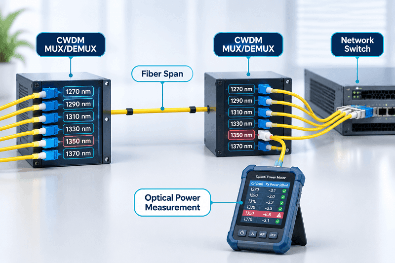
● One channel low in both directions points to a wavelength-specific MUX/DEMUX path or the corresponding modules. One channel low in a single direction points to a fault somewhere along that directional optical path, including the transmitter, patch cords, MUX/DEMUX path, fiber, or receiver side.
● A typical 10G 80 km CWDM module may transmit around 0 to +4 dBm and may have a receiver overload limit around -7 dBm, depending on the specific module. A short campus span can therefore be too bright rather than too dim.
● FiberMall’s published CWDM MUX/DEMUX specifications include insertion loss of up to 1.2 dB for selected 4-channel configurations and 2.4 dB for selected 8-channel configurations. These are product-specific values and must be checked against the exact SKU.
● Capture DDM at commissioning. Without a baseline, a drifting module, a dirty connector, or a damaged patch cord can be difficult to distinguish from one another.
Debugging a link now? Send the per-channel readings and the as-built map to FiberMall’s engineers for a second opinion. Request a link check.
Five Measurements That Drive CWDM Troubleshooting
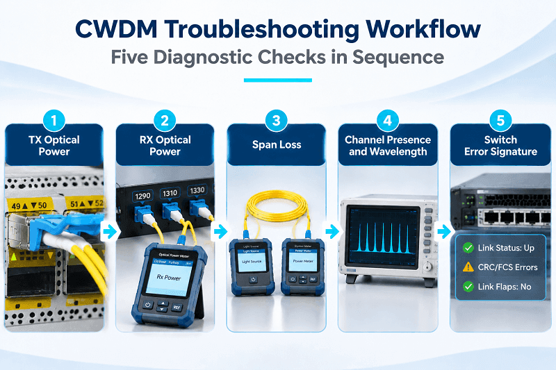
Every CWDM fault appears in at least one of five diagnostic checks. The first four are optical measurements; the fifth is a switch-side service check. Run them in this order, and each one removes a class of possible causes.
| # | Measurement | Instrument | Expected value | What a deviation proves |
| 1 | Transmit power, per module | CWDM DDM, or a meter on the module’s transmit port | 0 to +4 dBm for a 10G 80 km module | Dead, disabled, or unseated module; port shutdown |
| 2 | Receive power, per channel | Power meter at the demux channel port | Within 1 dB of the calculated budget | Low: loss in that channel’s path. High: too little loss, possible overload |
| 3 | Span loss, mux bypassed | Light source and meter, or an OTDR | Design value within 0.5 dB | High: connector, splice, bend, or fiber damage |
| 4 | Channel presence and wavelength | CWDM power meter or optical spectrum analyzer | Every lit channel present at its nominal wavelength | Missing or shifted: wrong optic, wrong port, drifted laser |
| 5 | Error signature at the switch | Interface counters and logs | Clean at line rate | CRC errors under load: overload or dispersion. Loss of signal: no light. Flaps: intermittent connection |
Measurement 1 proves whether the module is transmitting at all. Measurement 2 localizes the fault to a channel. Measurement 3 separates the plant from the mux.
Measurement 4 identifies the wavelength, which is where most CWDM faults actually live. Measurement 5 separates a power problem from a signal-quality problem.
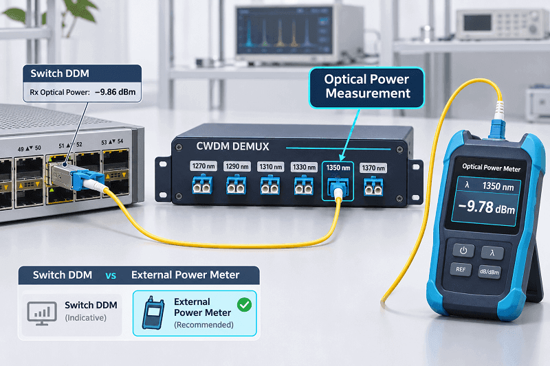
Measure at the Mux Port, Not Through the Switch
The switch’s DDM reports the optical power measured by the transceiver, which is useful for determining whether the received level is within the module’s operating range. It cannot tell you where the loss occurred. Take the reading at the demux channel port with a calibrated power meter, then compare it with the module’s DDM reading.
A small difference between DDM and an external meter should not be used by itself to identify a connector or patch-cord fault. SFF-8472 specifies absolute TX/RX optical-power accuracy of better than ±3 dB under the applicable conditions, and RX power may represent either average received power or OMA depending on the module implementation. Use the external meter and a reference-based loss measurement when making a pass/fail decision.
For preliminary link-budget calculations, connector-pair losses are often estimated at around 0.3 to 0.5 dB depending on the connector grade and project assumptions. That figure should not be treated as a diagnostic threshold.
The CWDM Troubleshooting Fault Tree: Six Faults
CWDM link troubleshooting gets faster once you stop treating symptoms as separate problems. Six common fault categories cover many field cases, and each has a signature that helps narrow the fault domain. Most begin as CWDM low receive power on a single channel, so comparison between channels is one of the fastest tests available.
| Fault | Signature | First check | Usual fix |
| 1. No light at either end | Transmit power absent or at the floor, loss of signal on both ends | Port admin state and TX disable | Enable the port, reseat, recode, replace |
| 2. One direction dead on single-fiber CWDM | One direction receives, the reverse is dark | Which half of the band each end transmits | Correct the pair map or swap the pigtails |
| 3. One channel low in both directions | Same deficit measured at both ends of that wavelength | Swap the module to a known-good mux port | Replace the module or repair the port |
| 4. All channels low in one direction | Every channel short by about the same amount | Span loss with the mux bypassed | Clean, re-terminate, replace patch cords, fix the bend |
| 5. Link up, errors under load | CRC errors at line rate, clean at idle, receive power high | Receive power and span length | Add 10 to 15 dB of attenuation |
| 6. One E-band channel weak, O-band clean | 1371 or 1391 nm short by 1 to 3 dB, other channels fine | Fiber vintage and measured attenuation at that channel | Move the channel or replace the fiber |
Fault 1: No Light at Either End
Check the transmit-disable state before touching hardware. A module reporting TX power near the measurement floor may be disabled, unseated, or genuinely faulty. The other common cause is coding: a switch that rejects a module’s EEPROM coding may keep the port down and log an unsupported-module error. Correct coding can resolve that condition without replacing the hardware.
Also verify the host port’s administrative and operational state before concluding that the optical module is faulty.
Fault 2: One Direction Dead on Single-Fiber CWDM
Single-fiber CWDM uses different wavelength groups for the two transmission directions. A common layout may put 1471 to 1531 nm in one direction and 1551 to 1611 nm in the other, depending on the specific MUX/DEMUX design.
When one direction is dark, the wavelength halves may be crossed or incorrectly mapped somewhere in the path. Read the wavelength labels at both MUX ports, then confirm the pigtail assignment against the approved A/B wavelength map.
Do not rely only on CH1, CH2, or CH3 labels because channel numbering is vendor-specific.

Fault 3: One Channel Low in Both Directions
If the 1471 nm channel is weak in both directions, the common fault domain is the wavelength-specific optical path: its corresponding MUX/DEMUX filter path, connectors, patch cords, or the two endpoint modules.
The passband must be checked against the selected MUX/DEMUX datasheet. For example, FiberMall’s selected 4-channel and 8-channel CWDM MUX/DEMUX products specify an ITU ±6.5 nm passband around the nominal center wavelength. This is a product specification and should not be treated as a universal passband requirement of ITU-T G.694.2.
If the module appears to be the suspect, swap it with a known-good module of the same wavelength and verify the result through a known-good path. Do not move a module to an arbitrary MUX channel simply because that port is known to be good; the test port must support the same wavelength and passband.
Fault 4: All Channels Low in One Direction
This usually indicates a common-path loss or a common transmitter/receiver-side problem. The number to trust is the one measured with the MUX/DEMUX bypassed.
Connector polish is a commonly overlooked fault. A UPC patch cord mated directly to an APC bulkhead is incompatible and can introduce excessive insertion loss and poor return loss at the same time. Bend radius violations, crushed patch cords, and heavy patch bundles can create a similar signature.
Measure the common fiber path first rather than assuming that the MUX/DEMUX is responsible.
Fault 5: Link Up, Errors Under Load
Two different physical-layer conditions can produce this symptom, and optical measurements help separate them.
High receive power on a short span can indicate receiver overload. Normal receive power on a long span can shift the investigation toward dispersion or other signal-quality limitations. However, CRC/FCS errors are symptoms, not proof of overload or dispersion. Dirty connectors, marginal optical power, excessive reflection, module degradation, fiber problems, or host-interface issues can produce similar behavior.
The CWDM distance guide covers the dispersion side; the next section covers receive overload.
Fault 6: One E-Band Channel Weak, O-Band Clean
Hydroxyl absorption near 1383 nm can raise attenuation on some legacy G.652.A/B fiber in the E-band. The effect can be particularly important around the 1371 and 1391 nm channels.
If those channels show significantly higher attenuation while 1471 nm and longer-wavelength channels remain normal, verify the fiber type and actual attenuation before replacing the transceiver.
The effect is wavelength-dependent and does not mean that every 1371–1451 nm channel is automatically unusable on every older fiber. Measured attenuation and the available link margin should determine the decision.
Illustrative example: A 1371 nm link on fiber installed in the 1990s may come in several dB below the same span measured at 1551 nm. If the module is replaced without measuring the wavelength-dependent fiber loss, the real cause can remain in the plant.
The CWDM wavelength chart lists which channels require particular attention on fiber whose characteristics cannot be verified.
When the Fault Is Intermittent
Intermittent faults often correlate with temperature, mechanical movement, or marginal optical margin.
CWDM transmitters using uncooled lasers can experience wavelength shifts with temperature. The magnitude of the shift is device-specific and must be evaluated against the transceiver’s specified wavelength tolerance and operating-temperature range. Do not assume a universal 0.1 nm/°C coefficient for every CWDM module.
A cabinet that heats up in the afternoon can therefore reduce the available wavelength margin of a marginal channel, particularly when the transmitter wavelength tolerance and MUX/DEMUX passband are already close to their limits.
Correlate the flaps with temperature first, then with patch-cord movement, before replacing anything. An OTDR trace on a dark strand at an appropriate test wavelength can help locate a tight bend or other localized event that a power meter may show only as a small loss.
When One Channel Fails While the Others Work
Four causes explain a single bad channel, and each has a different test:
- Wrong module wavelength in the port. Read the label on the module and the label on the port, in nanometers.
- Damaged wavelength-specific MUX/DEMUX path. Test the module through a known-good path of the same wavelength where the architecture allows it.
- Failing module. Swap it with a spare of the same wavelength and compatible specification.
- A fiber or connector problem on that channel’s patch path. Replace or test the relevant patch cords and connectors first.
CWDM port mapping is where this goes wrong most often. “CH1” is a vendor convention, not a universal wavelength designation, so one supplier’s channel 1 can be 1271 nm while another supplier’s CH1 starts at 1471 nm. Compare nanometers, never port numbers alone.
A four-channel 1470–1530 nm configuration uses the nominal ITU wavelengths 1471, 1491, 1511, and 1531 nm. Put a 1491 nm module in the 1511 nm port and the module is 20 nm away from the port’s nominal center wavelength, well outside a typical ±6.5 nm passband. The link may fail completely or operate with excessive loss, which can initially look like a marginal cable rather than a wavelength mismatch.
Specifying a replacement? FiberMall’s CWDM mux/demux modules list insertion loss and passband by configuration, and the mux selection guide explains how to read the datasheet.
Receive Overload: The Fault That Looks Like a Bad Module
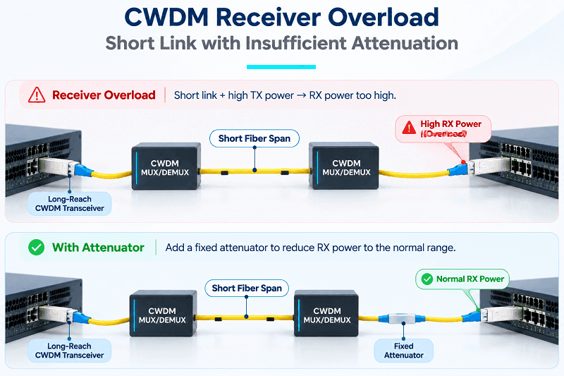
A 10G CWDM module built for 80 km is a long-reach part. The referenced FiberMall 10G 80 km CWDM SFP+ product is designed for long-reach operation, and typical 10G 80 km specifications may include TX power around 0 to +4 dBm with a receiver overload limit around -7 dBm. Always use the exact datasheet values for the module being tested.
Put a high-power long-reach module on a very short span and the receiver can operate above its overload limit.
Illustrative example: A network engineer lights a 1.8 km link between two buildings with 80 km modules because they are already in stock. The link comes up clean and runs normally overnight.
The next morning it begins throwing CRC errors, and the receive power in DDM reads about +1 dBm. Two modules are returned for replacement before anyone measures the actual span loss.
The arithmetic is straightforward. Assume a four-channel MUX/DEMUX pair contributes 2.4 dB total, connectors contribute 0.6 dB, and 1.8 km of fiber contributes approximately 0.5 dB. The estimated total path loss is:
2.4 + 0.6 + 0.5 = 3.5 dB
With a transmitter output range of 0 to +4 dBm, the estimated receive power could therefore be approximately -3.5 to +0.5 dBm, depending on the actual transmitter output.
That range is well above a -7 dBm receiver overload limit.
The fix is to select attenuation based on the measured receive power, the receiver overload limit, and the required operating margin. In this example, a 10 dB fixed LC attenuator may be appropriate, but the actual attenuator value must be calculated from the measured conditions.
The better fix happens at design time: match module reach to span length, and keep shorter-reach optics in stock for short links. 10G CWDM SFP+ modules are available in multiple reach classes, including 10, 20, 40, 60, 80, and 100 km in some product ranges, depending on wavelength and SKU.
Reading DDM and Setting a Baseline
What DDM Actually Tells You
DDM follows SFF-8472, which defines the management interface and diagnostic parameters for SFP/SFP+ modules. A compliant implementation can report parameters such as temperature, supply voltage, bias current, transmit power, and receive power.
For troubleshooting, the optical-power readings are particularly useful, but they must be interpreted within the specified measurement accuracy and operating range.
The first useful environmental indicator is temperature, because an uncooled laser’s wavelength can shift with temperature. However, the DDM temperature reading is normally a transceiver temperature measurement, not a direct measurement of laser wavelength or laser temperature unless the module provides a dedicated laser-temperature monitor.
The second is the pair of optical-power readings. SFF-8472 specifies better than ±3 dB absolute accuracy for TX and RX optical-power measurements under the applicable conditions. That is useful for trend analysis but not precise enough to replace a calibrated external power meter when making a fault verdict.
Thresholds are also vendor-set. A low-power alarm means the manufacturer has defined that boundary as abnormal for the module. An alarm is a prompt to investigate, not a complete diagnosis.
The Commissioning Baseline That Prevents Most Calls
The difference between a two-minute diagnosis and a two-day one is a baseline captured at turn-up. It takes about ten minutes per link.
| Check | Pass criterion | Record |
| Receive power, per channel | Within 1 dB of the calculated budget | Value per channel, both ends |
| DDM snapshot | Every parameter inside the vendor’s window | Full reading, with date |
| Port map | Every port labeled with its wavelength, not its channel number | Photo of the mux faceplate |
| Span loss | Measured value matches the design within 0.5 dB | Meter model and calibration date |
| Attenuators | Fitted where the span is short enough to overload | Value and location |
At a hospital in Ohio, a technician named Ray recorded per-channel receive power at turn-up and taped the printout inside the cabinet door. Eighteen months later the 1491 nm channel had fallen 3.2 dB while its neighbors held steady. A patch cord crushed behind the door hinge was the cause. Without the baseline, the drop looked like a failing module and would have cost a spare and a second visit.
A reading without a baseline is an opinion. With a baseline, a 3 dB drop over eighteen months names its own cause: a dirty connector, a failing patch cord, or a module on its way out. The CWDM network design guide covers the acceptance test that this routine plugs into.
When It Really Is the Module: A Swap and RMA Protocol
Before a module is declared faulty, prove the fault through controlled testing. Two modules of the same wavelength, tested through a known-good optical path with an appropriate attenuator and a known-good switch port, can help determine whether the fault follows the module.
Record four things while you are there: the DDM readings from the suspect module, the measured receive power at the demux, the part number and serial number, and the coding or firmware version. That record separates a warranty claim from a guess.
The swap sequence that avoids wasted visits is short. Move the suspect module to a known-good switch port with a known-good patch cord, while keeping the wavelength assignment and optical path compatible.
If the fault follows the module, replace or RMA the module. If the fault stays with the switch port, investigate the host platform. If it stays with the same wavelength-specific optical path, investigate the MUX/DEMUX, patch cord, connector, or fiber plant. If a replacement shows the same signature, stop swapping modules: the fault is likely elsewhere in the plant.
Faulty modules are covered under FiberMall’s warranty, subject to the applicable warranty terms and confirmation of the fault. Every unit ships after the testing described on the quality assurance page, so a repeat failure should trigger a review of the installation, test evidence, coding, and optical path rather than automatically assuming another module is defective.
FAQ
Why is my CWDM link down?
Common causes include a disabled or unseated module, incorrect module coding, a wavelength mismatch, excessive optical loss, or a problem in one channel’s patch path. Check transmit power first, then per-channel receive power at the demux.
Why does one CWDM channel fail while the others work?
Common causes are a module in the wrong wavelength port, a damaged wavelength-specific MUX/DEMUX path, and a bad patch cord or connector on that channel’s path. Compare the module label and the port label in nanometers, then test the module through a known-good path of the same wavelength.
Can a CWDM link have too much power?
Yes. CWDM receiver overload happens when the received optical power exceeds the receiver’s specified maximum input level. An 80 km module on a very short span can produce excessive receive power because the fiber path introduces too little loss.
Measure receive power and calculate the required attenuation from the measured level, receiver overload limit, and desired margin. Do not automatically add a fixed 10 or 15 dB attenuator without checking the actual values.
What should I check before replacing a CWDM module?
Transmit power, receive power per channel, span loss with the MUX/DEMUX bypassed, the wavelength/port map, and the relevant interface counters.
If the fault follows the module across a known-good compatible port and patch cord, the module becomes the primary suspect. If it stays with the optical path or port, continue troubleshooting the path rather than replacing another module.
What tools do I need to troubleshoot CWDM?
A calibrated optical power meter, a light source or OTDR, a CWDM channel power meter or optical spectrum analyzer, an inspection scope, and cleaning supplies.
A meter that can read individual channels saves far more time than a broadband meter when troubleshooting a multiplexed CWDM link.
CWDM Troubleshooting: Measure Before You Swap
CWDM troubleshooting is a short list of readings and diagnostic checks, not a long list of suspects. Transmit power, receive power per channel, span loss, channel presence, and the error signature will narrow the fault domain in most cases, and the six fault categories cover many of the problems those checks reveal.
Carry three habits into the next outage.
Measure at the MUX/DEMUX port rather than trusting DDM alone.
Write the baseline down at commissioning, because a number without history is difficult to interpret.
And keep a range of attenuators available, since a fault that looks like a dead module can sometimes be a receiver operating above its specified overload limit.
The CWDM SFP guide covers module selection by rate and reach, including long-reach 80 km parts that can create overload conditions on short spans. For networks with amplifiers, DWDM troubleshooting adds OSNR and gain-tilt considerations that do not normally apply to a passive CWDM plant.
If the readings do not add up, send them over. FiberMall’s engineers can check the per-channel numbers and the port map against the design and help identify which end or component to investigate first.
Related Products:
-
 Passive CWDM Double Fiber Mux & Demux Module 18 CH (1270-1610nm) LC/UPC 1U Rack
$630.00
-
Passive CWDM Double Fiber Mux & Demux Module 16 CH (1310-1610nm) 1U Rack
$570.00
-
CWDM MUX 8CH 16 Wavelengths (TX: 1310/1330/1390/1410/1470/1490/1550/1570nm RX: 1350/1370/1430/1450/1510/1530/1590/1610nm) LC/UPC Single Fiber 1U Rack
$320.00
-
Passive CWDM Double Fiber Mux & Demux Module 8CH (1470-1610nm) LC/UPC LGX BOX
$280.00
-
CWDM MUX 4CH 8 Wavelengths (TX: 1470/1490/1510/1530nm RX: 1550/1570/1590/1610nm) with Express Port LC/UPC Single Fiber LGX BOX
$150.00
-
Passive CWDM Double Fiber Mux & Demux Module 4 CH (1470-1530nm) LC/UPC LGX BOX
$150.00
-
Passive CWDM Single Fiber 1 Channel OADM LGX BOX
$70.00
-
Passive CWDM Double Fiber 2 Channels OADM LGX BOX
$130.00
-
Passive CWDM Double Fiber 4 Channels OADM LGX BOX
$250.00
-
SFP-CW10G27-40C 10G CWDM SFP+ 1270nm 40km LC SMF DDM Transceiver Module
$95.00
-
SFP-CW10G27-10C 10G CWDM SFP+ 1270nm 10km LC SMF DDM Transceiver Module
$60.00
-
SFP-CW10G59-05C 10G CWDM SFP+ 1590nm 5km LC SMF DDM Transceiver Module
$60.00
-
SFP-CW10G27-20C 10G CWDM SFP+ 1270nm 20km LC SMF DDM Transceiver Module
$75.00
-
SFP-CW10G47-100C 10G CWDM SFP+ 1470nm 100km LC SMF DDM Transceiver Module
$280.00