
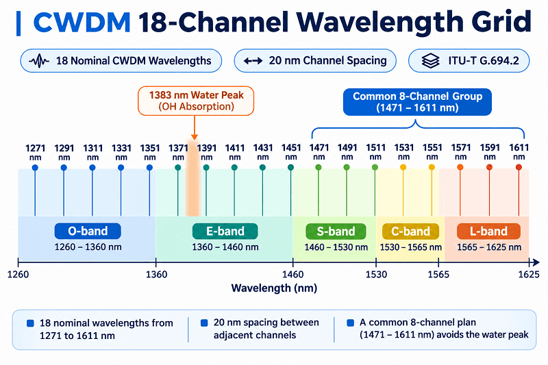
The CWDM wavelength grid covers 18 nominal center wavelengths from 1271 to 1611 nm, spaced 20 nm apart under ITU-T G.694.2. Many conventional CWDM links use the eight higher-wavelength channels, from 1471 through 1611 nm, because they avoid the water-peak region that can cause high attenuation on older single-mode fiber.
That’s the short answer. The chart below is the longer one, and it addresses a question that frequently comes up during channel planning: is the first channel 1270 or 1271 nm?
Both numbers appear in industry documentation. Neither is necessarily a typo.
Consider an illustrative case: Priya, a transport engineer at a regional ISP, is preparing an overnight cutover. Her eight-channel span comes up with six channels carrying traffic, while the 1371 and 1391 nm channels remain down. The installed fiber turns out to be G.652.B rather than the low-water-peak fiber shown in the as-built drawings.
The optics may be functioning correctly; the unverified fiber attenuation at those wavelengths could be enough to exceed the link budget.
This page is a wavelength chart, not another general CWDM explainer. It covers all 18 wavelengths, their optical bands and fiber considerations, the color-code convention and its limits, four ready-made channel plans, and the wavelength-tolerance considerations behind 20 nm spacing. For the fundamentals, start with our complete CWDM guide.
Key Takeaways
- ITU-T G.694.2 defines 18 CWDM wavelengths from 1271 to 1611 nm, numbered channel 27 through 61 in steps of 2.
- The 1 nm shift from 1270 to 1271 happened in the 12/2003 revision; modules marked 1470 and 1471 nm are the same channel.
- Channels 1371 through 1451 fall in the E-band water-peak region and need G.652.C/D fiber or a measured link.
- The default 8-channel plan is 1471 to 1611 nm in 20 nm steps, which avoids the water peak entirely.
- Color codes are a vendor convention, not part of the ITU standard, and they disagree between suppliers.
CWDM Wavelength Chart: All 18 Channels
CWDM uses 18 nominal center wavelengths from 1271 to 1611 nm, spaced 20 nm apart under ITU-T G.694.2. The grid specifies wavelengths rather than a universal channel-numbering sequence. Conventional CWDM transmitters typically allow several nanometers of wavelength variation around each nominal center; the actual MUX/DEMUX passband must be checked separately. The chart below lists all 18 wavelengths, indexed here from 1 to 18 for reference.
| ITU channel | Wavelength (nm) | Rounded label (nm) | Band | Planning note |
| 27 | 1271 | 1270 | O | CWDM4 lane 1; safe on any G.652 |
| 29 | 1291 | 1290 | O | CWDM4 lane 2 |
| 31 | 1311 | 1310 | O | A channel, not the 1310 window |
| 33 | 1331 | 1330 | O | CWDM4 lane 4 |
| 35 | 1351 | 1350 | O | Upper edge of O-band; check fiber |
| 37 | 1371 | 1370 | E | Near the water peak; measure first |
| 39 | 1391 | 1390 | E | Near the water peak; measure first |
| 41 | 1411 | 1410 | E | E-band; G.652.C/D only |
| 43 | 1431 | 1430 | E | E-band; G.652.C/D only |
| 45 | 1451 | 1450 | E | E-band; G.652.C/D only |
| 47 | 1471 | 1470 | S | Standard 8-channel start; gray |
| 49 | 1491 | 1490 | S | Violet in most catalogs |
| 51 | 1511 | 1510 | S | Blue |
| 53 | 1531 | 1530 | C | Green; inside the EDFA window |
| 55 | 1551 | 1550 | C | Yellow; not the 1550 window |
| 57 | 1571 | 1570 | L | Orange |
| 59 | 1591 | 1590 | L | Red |
| 61 | 1611 | 1610 | L | Brown; top of the grid |
Two details can cause confusion when this chart is used in a purchase order. First, the rounded-label column: module labels and purchase orders often use 1270, 1470, or 1610 nm, while current engineering specifications and some MUX port labels use 1271, 1471, or 1611 nm.
Second, channel numbers are not universal. A buyer should identify the required wavelength rather than relying on a supplier’s “CH9” designation alone.
| You will see | It means | Watch out for |
| 1470 nm module label, 1471 nm MUX port | Usually the same intended CWDM wavelength channel | Confirm transmitter wavelength range and MUX passband |
| 1310 nm window | A broadband pass-through port, often covering part or much of the O-band | Not the same as a dedicated 1311 nm CWDM channel; overlapping ports may be mutually exclusive |
| 1550 nm window | A broadband pass-through port near 1550 nm | Not the same as a dedicated 1551 nm CWDM channel; check overlap |
| CH1 to CH18 | A vendor-specific port index | Numbering and wavelength order vary by supplier |
If you are building a bill of materials from this table, send the port list to our team. We can map it against the relevant CWDM MUX/DEMUX configurations before you commit to a part number.
How to Read the CWDM Wavelength Chart
Channel number, wavelength, and the 1 to 18 index
ITU-T G.694.2 establishes nominal center wavelengths, not a mandatory sequence of channel numbers such as 27, 29, or 31. Its 18 listed wavelengths start at 1271 nm and end at 1611 nm, increasing in 20 nm steps. The wavelength grid is standardized; the numbering and labels on commercial products may differ.
The 1 to 18 index found in some MUX datasheets is a vendor convenience, not an ITU-T channel-numbering requirement. A “CH1” port on one supplier’s module may be 1471 nm, while another supplier starts CH1 at 1271 nm. When comparing quotes, use the wavelength in nanometers rather than the port number alone.
1270 or 1271 nm? The one-nanometer revision
The 2002 edition of ITU-T G.694.2 used nominal center wavelengths from 1270 to 1610 nm. The December 2003 revision shifted the grid by 1 nm to 1271 through 1611 nm to align with industry practice while maintaining symmetrical wavelength deviations.
The old and new labels therefore generally identify the same intended CWDM channel. For example, a transceiver marked 1470 nm and a MUX port marked 1471 nm will often be compatible, provided the transmitter’s specified wavelength range falls within the MUX passband. The label difference alone does not establish the exact spectral specifications of either component.
Consider another illustrative case: Tomas, a university network architect, receives SFPs labeled 1470 nm and a MUX datasheet listing 1471 nm. The procurement team initially flags them as incompatible. After checking the optical specifications with the suppliers, the team confirms that the wavelength ranges are compatible. The original spreadsheet, however, still reflects the naming discrepancy.
Use 1271 through 1611 nm in new engineering documents. Include the rounded labels where necessary to match existing product labels or purchase orders, and verify the actual optical specifications.
Passband, drift, and why CWDM channel spacing is 20 nm
A CWDM channel is identified by a nominal center wavelength, but the transmitter does not emit at one perfectly fixed wavelength under all conditions. CWDM applications commonly allow a total wavelength excursion of roughly 12–14 nm around the nominal center, depending on the applicable transceiver specification. This permitted transmitter excursion is not automatically identical to a MUX/DEMUX filter’s guaranteed passband.
Within the allowed range, an uncooled CWDM laser’s wavelength can shift with temperature. For illustration, a laser with a temperature coefficient of approximately 0.1 nm/°C could shift by around 7 nm across a 70°C temperature change. Actual performance also depends on its starting wavelength, operating temperature, aging, and the manufacturer’s end-of-life specifications. Designers must confirm that the transmitter remains within the usable filter passband across these conditions.
This relatively wide channel spacing helps reduce CWDM costs by enabling simpler laser temperature control and comparatively tolerant optical filtering. DWDM commonly uses 100 GHz or 50 GHz spacing—approximately 0.8 or 0.4 nm near 1550 nm—and also supports other fixed or flexible-grid spacings. Its tighter spacing generally requires more precise wavelength control. Our DWDM channel plan guide explains that grid in more detail.
CWDM Bands: Where Each Wavelength Sits
Which band each wavelength sits in
The 18 CWDM wavelengths span five optical transmission bands. These distinctions matter because fiber attenuation and component characteristics vary with wavelength.
| Band | Range | CWDM channels in it |
| O (original) | 1260 to 1360 nm | 1271, 1291, 1311, 1331, 1351 |
| E (extended) | 1360 to 1460 nm | 1371, 1391, 1411, 1431, 1451 |
| S (short) | 1460 to 1530 nm | 1471, 1491, 1511 |
| C (conventional) | 1530 to 1565 nm | 1531, 1551 |
| L (long) | 1565 to 1625 nm | 1571, 1591, 1611 |
The O-band includes the region commonly used by legacy 1310 nm systems. On typical G.652 fiber, attenuation is generally lower around 1550 nm in the C-band than around 1310 nm in the O-band. The C-band is also widely used for EDFA amplification. The L-band offers additional low-loss wavelengths, although attenuation and bending sensitivity must be checked at the longer end. A conventional eight-channel CWDM plan uses the S-, C-, and L-band channels primarily because it avoids the central water-peak region, not because every one of those wavelengths has the lowest fiber loss.
The E-band requires particular attention.
The CWDM channels to avoid on legacy fiber
Hydroxyl (OH) groups in older optical fiber absorb light near 1383 nm. This absorption feature, known as the water peak, can significantly increase attenuation around that wavelength on some legacy G.652.A and G.652.B fiber. It is a fiber characteristic, not necessarily a fault in the optical transceivers.
The impact depends on the actual fiber. Low-water-peak G.652.C and G.652.D fiber is designed to reduce attenuation in this region. Under ITU-T G.652, the current G.652.D cable attenuation limit at 1383 ± 3 nm after hydrogen aging is 0.40 dB/km; individual products may perform better. Older fiber can exhibit substantially higher loss near the water peak, sometimes exceeding 1 dB/km. The effect is wavelength-dependent, however, so it is not correct to assume that every channel from 1371 to 1451 nm is unusable on all G.652.A/B links.
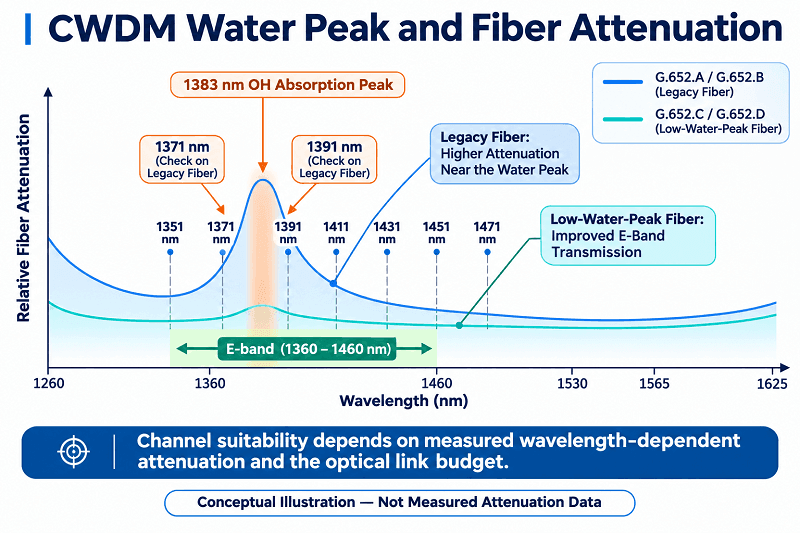
Warning: The 1371 and 1391 nm channels lie close to the 1383 nm water peak. On unknown or legacy fiber, confirm the actual attenuation and link margin before including them in a channel plan. The 1411 nm channel may also require particular attention.
The practical rule is to use a higher-wavelength plan, such as 1471 to 1611 nm, when fiber characteristics cannot be verified and the link budget permits. On confirmed low-water-peak G.652.D fiber, E-band channels may be practical for expansion, subject to optical budget and MUX/DEMUX compatibility. On older fiber, measured attenuation—not fiber category alone—should determine which channels are suitable.
CWDM Color Code Chart: A Vendor Convention
Colored SFPs can use pull-tab, latch, or label colors to help identify their wavelengths. These colors are useful during installation and troubleshooting, but they are not specified by ITU-T G.694.2 and are not guaranteed to match across manufacturers.
| Wavelength | Common color | Divergence to watch |
| 1471 nm | Gray | Cisco labels 1470 nm gray; some catalogs list it as violet |
| 1491 nm | Violet | Cisco labels 1490 nm violet; several third-party catalogs invert the two |
| 1511 nm | Blue | Consistent across major vendors |
| 1531 nm | Green | Consistent |
| 1551 nm | Yellow | Consistent |
| 1571 nm | Orange | Consistent |
| 1591 nm | Red | Consistent |
| 1611 nm | Brown | Consistent |
The 1470 and 1490 nm pair deserves special attention when equipment from different suppliers is mixed. Cisco’s documented convention assigns gray to 1470 nm and violet to 1490 nm, but other vendors may use different identification schemes. There is no universal ITU-T color code for the ten lower CWDM wavelengths from 1271 to 1451 nm either.
Treat color as a convenience, not a specification. Read the printed wavelength on each transceiver, and confirm it against the MUX port specification before connecting the link.
Choosing a CWDM Channel Plan
The standard 8-channel plan
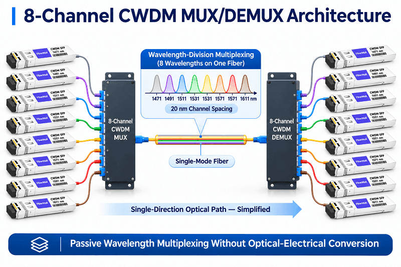
Every plan below draws from the same 18 nominal CWDM wavelengths. The main difference is how many wavelengths are used. A common eight-channel configuration uses 1471 through 1611 nm. Those eight channels occupy the S-, C-, and L-bands and avoid the main water-peak region. They are available in many standard eight-channel passive MUX/DEMUX products.
The optical link budget, rather than the wavelength chart alone, determines reach. As an illustrative calculation, an 80 km span at an assumed 0.2 dB/km would have 16 dB of fiber loss. Two passive MUX/DEMUX units with 2.4 dB insertion loss each would add 4.8 dB, while connectors and splices might add another 1–2 dB. The resulting loss is approximately 21.8–22.8 dB before adding an engineering margin. Actual fiber loss must be assessed at each operating wavelength, especially toward 1471 and 1611 nm. Whether a 10G CWDM link can support 80 km depends on the specific transceiver’s optical budget and all other link requirements; 80 km is not a universal guarantee.
The exact figures depend on the selected components. Our CWDM MUX/DEMUX guide provides insertion-loss specifications and link-budget examples.
4-channel and 16-channel plans
Four-channel configurations are commonly used in smaller campus networks and video transport applications. One possible plan starts at 1471 nm and uses 1471, 1491, 1511, and 1531 nm. Other four-channel port groups are also sold, so check the product’s actual wavelength list.
A 16-channel plan can use 1311 through 1611 nm, leaving out the two lowest wavelengths. Low-water-peak fiber is preferred for its E-band channels, unless measured loss confirms that the installed fiber can support them. A suitable 16- or 18-channel MUX is required, and its insertion loss may be higher than that of a simpler eight-channel device, depending on design.
| Plan | Channels | Fiber requirement | Typical use |
| 4-channel | 1471 to 1531 nm | Any G.652 | Campus, CCTV, small metro |
| 8-channel | 1471 to 1611 nm | Any G.652 | Metro, DCI edge, enterprise |
| 16-channel | 1311 to 1611 nm | G.652.C/D preferred | High-count metro rings |
| 18-channel | 1271 to 1611 nm | G.652.C/D required | Full-grid passive transport |
O-band plans for 5G fronthaul
Some 5G fronthaul deployments favor O-band wavelengths for relatively short links and cost-effective optics. The O-band includes five CWDM wavelengths: 1271, 1291, 1311, 1331, and 1351 nm.
A six-channel plan can add 1371 nm, close to the water-peak region. On suitable G.652.D fiber this may be feasible, subject to the link budget. On leased or legacy fiber, verify attenuation at the selected wavelengths before finalizing the order.
Legacy 1310 and 1550 windows
Some MUX/DEMUX modules include a broadband pass-through port, often described as a 1310 nm window and, in certain designs, a similar port around 1550 nm. The exact passband depends on the product. These broadband ports are not the same as dedicated CWDM wavelength channels.
For example, a 1310 nm pass-through port may cover much of 1260–1360 nm to carry an existing 1310 nm service. A dedicated 1311 nm CWDM channel is a separate, narrower filtered path. Because these wavelength ranges overlap, the pass-through port and overlapping dedicated CWDM ports generally cannot be used simultaneously on the same fiber path unless the equipment is expressly designed to support the arrangement. Similar checks apply to a broadband 1550 nm window and the CWDM channels it overlaps.
FiberMall’s eight-channel configurations may include an additional 1310 nm pass-through window for legacy traffic. If your plan includes such a service, tell us when requesting a quote so we can confirm the actual port layout, passbands, and any mutually exclusive channels.
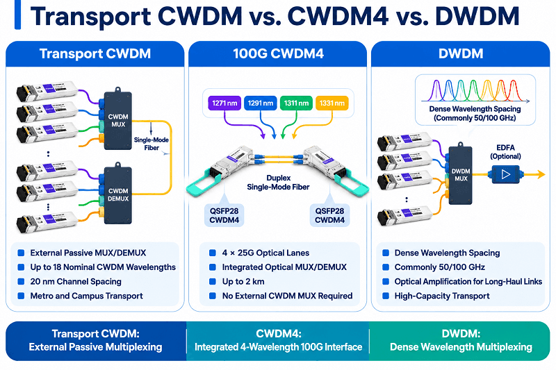
CWDM Wavelengths vs CWDM4 and DWDM
CWDM4 is not simply another name for transport CWDM. It is a 100G optical interface defined by the 100G CWDM4 multi-source agreement, using four optical wavelengths—1271, 1291, 1311, and 1331 nm—each carrying approximately 25 Gb/s of data over a duplex single-mode fiber pair for distances up to 2 km.
CWDM4 shares both the 20 nm wavelength-spacing principle and four nominal wavelength values with the CWDM grid. Its optical multiplexing and demultiplexing are integrated into the transceivers, however, so a standard CWDM4 link does not require external transport CWDM MUX/DEMUX modules and is not designed as an 80 km add/drop transport system.
| CWDM transport | CWDM4 | DWDM | |
| Wavelengths | 18, 20 nm spacing | 4 fixed | 40 to 160+, 0.4 or 0.8 nm |
| Reach | Up to about 80 km | Up to 2 km | Hundreds of km, amplified |
| Amplification | Rarely used | No | Yes, EDFA |
| Typical use | Metro, campus, fronthaul | 100G data center links | Long haul, DCI backbone |
If you are choosing between transport technologies rather than reading a wavelength table, our CWDM vs DWDM comparison covers the cost and reach trade-offs.
CWDM Wavelengths FAQ
What are the CWDM wavelengths?
They are the 18 nominal center wavelengths in ITU-T G.694.2: 1271, 1291, 1311, 1331, 1351, 1371, 1391, 1411, 1431, 1451, 1471, 1491, 1511, 1531, 1551, 1571, 1591, and 1611 nm. Each wavelength is spaced 20 nm from the next.
How many wavelengths does CWDM support?
The ITU-T G.694.2 grid contains 18 nominal wavelength positions, which can support up to 18 wavelengths in a suitable WDM design. Many practical deployments use four or eight channels, while higher-count systems are also available. The number of channels you can deploy depends on the MUX/DEMUX, transceivers, available fiber, and optical link budget.
What is the CWDM wavelength range?
1271 to 1611 nm, a span of 340 nm between the first and last nominal center wavelengths. Some vendor documentation uses rounded labels from 1270 to 1610 nm, consistent with the original 2002 grid.
Which CWDM channels should I avoid?
On unknown or legacy G.652.A/B fiber, assess wavelengths near the 1383 nm water peak before using them, especially 1371 and 1391 nm and, where relevant, 1411 nm. Other E-band channels also require wavelength-specific attenuation checks; they are not automatically unusable. G.652.C/D low-water-peak fiber generally provides greater flexibility for E-band channel planning.
Is CWDM4 the same as CWDM?
No. CWDM4 uses four wavelengths from the CWDM grid—1271, 1291, 1311, and 1331 nm—for a 100G data center interface with a reach of up to 2 km. It uses integrated optical wavelength multiplexing rather than an external passive CWDM transport channel plan.
Getting the Chart Into the Field
Imagine Mei, a network engineer at a colocation provider in Singapore, printing this chart on A4 paper, laminating it, and keeping it inside the door of each passive optical enclosure. Her reasoning is simple: when a link drops at 2 a.m., the on-call technician should be able to check the wavelength plan without searching online.
That’s a useful role for a CWDM wavelength chart. It is a quick reference tool, not a substitute for a product datasheet or measured optical link budget.
Three checks are worth doing before you build a plan from it:
- Confirm the fiber type and, where needed, measure wavelength-dependent attenuation, especially around the E-band.
- Compare MUX port wavelengths with transmitter specifications rather than relying on rounded labels or vendor channel numbers alone.
- Verify whether any 1310 or 1550 nm pass-through window overlaps with dedicated CWDM ports or services in the proposed configuration.
Our engineers can review a channel plan against your span length, fiber type, and MUX datasheet at no cost. Send us the plan, and we’ll flag channels that may require further loss measurements or compatibility checks before you order the optics.
Related Products:
-
 Passive CWDM Double Fiber Mux & Demux Module 18 CH (1270-1610nm) LC/UPC 1U Rack
$630.00
-
Passive CWDM Double Fiber Mux & Demux Module 16 CH (1310-1610nm) 1U Rack
$570.00
-
CWDM MUX 8CH 16 Wavelengths (TX: 1310/1330/1390/1410/1470/1490/1550/1570nm RX: 1350/1370/1430/1450/1510/1530/1590/1610nm) LC/UPC Single Fiber 1U Rack
$320.00
-
Passive CWDM Double Fiber Mux & Demux Module 8CH (1470-1610nm) LC/UPC LGX BOX
$280.00
-
CWDM MUX 4CH 8 Wavelengths (TX: 1470/1490/1510/1530nm RX: 1550/1570/1590/1610nm) with Express Port LC/UPC Single Fiber LGX BOX
$150.00
-
Passive CWDM Double Fiber Mux & Demux Module 4 CH (1470-1530nm) LC/UPC LGX BOX
$150.00
-
Passive CWDM Single Fiber 1 Channel OADM LGX BOX
$70.00
-
Passive CWDM Double Fiber 2 Channels OADM LGX BOX
$130.00
-
Passive CWDM Double Fiber 4 Channels OADM LGX BOX
$250.00
-
SFP-CW10G27-40C 10G CWDM SFP+ 1270nm 40km LC SMF DDM Transceiver Module
$95.00
-
SFP-CW10G27-10C 10G CWDM SFP+ 1270nm 10km LC SMF DDM Transceiver Module
$60.00
-
SFP-CW10G59-05C 10G CWDM SFP+ 1590nm 5km LC SMF DDM Transceiver Module
$60.00
-
SFP-CW10G27-20C 10G CWDM SFP+ 1270nm 20km LC SMF DDM Transceiver Module
$75.00
-
SFP-CW10G47-100C 10G CWDM SFP+ 1470nm 100km LC SMF DDM Transceiver Module
$280.00